1
Head Office
17, rue du Petit Albi
BP 8244
95801 Cergy Pontoise Cedex
FRANCE
tel +33 1 34 20 70 00
fax +33 1 34 20 70 47
http://www.thomsonbroadcast.com
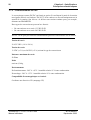
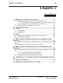
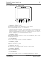
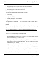
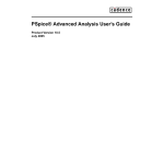
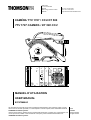
CAMÉRA TTV 1707 / CCU DT 500
TTV 1707 CAMERA / DT 500 CCU
ON AIR
I
CAMERA
CAM.LOCK
CAM. OK
RCP
MAINS
ON
O
EXT.REF.
OFF
CABLE
OPEN
COARSE
H
FINE
SC
SC/H
FRONT
PORCH
TRIAX
GENLOCK/
VIDEO
SOUND/
AUX
CCU
POWER
MANUEL D’UTILISATION
USER MANUAL
B1707M00LD
Ce document et toute mise à jour et/ou complèment d'information, ainsi que leurs copies, ne peuvent en aucun cas être reproduits, ni communiqués à une tierce partie, sans autorisation écrite de
THOMSON broadcast systems.
This document and any updates and/or supplemental information, including any copies thereof, can
not be reproduced, neither communicated to a third party, without written authorisation from
THOMSON broadcast systems.
© 2000
THOMSON
broadcast systems
All rights reserved.
PAGE BLANCHE
BLANK PAGE
3
SOMMAIRE / CONTENTS
SECTION 1 - VERSION FRANçAISE
CONSIGNES DE SECURITE .............................................................. 9
CHAPITRE 1
SPÉCIFICATIONS ............................................................................ 15
CHAPITRE 2
INSTALLATION ................................................................................ 29
CHAPITRE 3
CAMÉRA - CONVERTISSEUR DC/DC ............................................ 53
CHAPITRE 4
CONTRÔLE DE VOIE ....................................................................... 77
CHAPITRE 5
VISEURS 4 CM ET 14 CM ................................................................ 87
B1707M00LD
THOMSON
4
SECTION 2 - ENGLISH VERSION
SAFETY INSTRUCTIONS ............................................................... 103
CHAPTER 1
SPECIFICATIONS ........................................................................... 109
CHAPTER 2
INSTALLATION ............................................................................... 123
CHAPTER 3
CAMERA - DC/DC CONVERTER ................................................... 147
CHAPTER 4
CHANNEL CONTROL UNIT ........................................................... 169
CHAPTER 5
4 CM/14 CM VIEWFINDERS ........................................................... 179
THOMSON
B1707M00LD
SECTION 1 - Version Française
5
SECTION 1 - VERSION FRANÇAISE
SOMMAIRE
CONSIGNES DE SECURITE ............................................................... 9
CHAPITRE 1
SPÉCIFICATIONS ............................................................................. 15
1.1 - Principales caractéristiques ........................................ 17
1.1.1 - Contrôle de voie ......................................................................
1.1.2 - Caméra .....................................................................................
1.1.3 - Convertisseurs DC/DC ............................................................
1.1.4 - Longueur du câble triaxial caméra / contrôle de voie..........
17
18
20
21
1.2 - Présentation .................................................................. 22
1.3 - Configuration................................................................. 26
1.4 - Principes généraux d'exploitation............................... 27
1.4.1 - Contrôle de l'équipement à partir d'un pupitre..................... 27
1.5 - Principes généraux de maintenance ........................... 28
CHAPITRE 2
INSTALLATION ................................................................................. 29
2.1 - Montage du contrôle de voie en baie .......................... 31
2.1.1 - Montage du contrôle de voie avec un accessoire 1/2 19" ... 31
2.1.2 - Montage de deux contrôles de voie en baie ......................... 34
2.2 - Alimentation secteur..................................................... 36
2.3 - Audio .............................................................................. 37
B1707M00LD
Septembre 2000
THOMSON TTV1707 / CCU DT500
Manuel utilisateur
6
SECTION 1 - Version Française
2.3.1 - Son Ambiance ......................................................................... 37
2.3.2 - Interphonie............................................................................... 38
2.4 - Vidéo............................................................................... 40
2.4.1 - Sélection du standard de sortie de la vidéo composite ...... 40
2.4.2 - Commutateurs de test ............................................................ 40
2.5 - Mise en phase de l'équipement avec une installation de
type numérique ...................................................................... 41
2.5.1 - Equipement asservi sur une référence externe connectée sur
l'entrée "GEN LOCK" ......................................................................... 42
2.5.2 - Equipement sans référence externe (mode libre)................ 43
2.6 - Mise en phase de l'équipement avec une installation de
type analogique ..................................................................... 44
2.6.1 - Equipement asservi sur une référence externe connectée sur
l'entrée "GEN LOCK" ......................................................................... 45
2.6.2 - Equipement sans référence externe (mode libre)................ 48
2.7 - Adaptation aux commandes externes de signalisations
d’antenne................................................................................ 49
2.8 - Pupitre d’exploitation.................................................... 50
2.9 - Montage de l'attache câble sur la caméra................... 52
CHAPITRE 3
CAMÉRA - CONVERTISSEUR DC/DC.............................................. 53
3.1 - Description de la caméra .............................................. 55
3.1.1 - Dimensions, poids ..................................................................
3.1.2 - Côté droit .................................................................................
3.1.3 - Côté gauche.............................................................................
3.1.4 - Face arrière..............................................................................
55
56
58
60
3.2 - Convertisseur DC/DC externe ...................................... 68
3.3 - Exploitation de la caméra ............................................. 70
THOMSON TTV1707 / CCU DT500
Manuel utilisateur
B1707M00LD
Septembre 2000
SECTION 1 - Version Française
7
3.3.1 - Commandes cadreur............................................................... 70
3.3.2 - Fonctions d'exploitation cadreur ........................................... 71
CHAPITRE 4
CONTRÔLE DE VOIE ........................................................................ 77
4.1 - Description .................................................................... 79
4.1.1 - Dimensions, poids................................................................... 79
4.1.2 - Face arrière .............................................................................. 80
4.1.3 - Face avant ................................................................................ 85
CHAPITRE 5
VISEURS 4 CM ET 14 CM ................................................................. 87
5.1 - Viseur 4 cm .................................................................... 89
5.1.1 - Principales caractéristiques...................................................
5.1.2 - Commandes et fonctions........................................................
5.1.3 - Signalisations lumineuses .....................................................
5.1.4 - Réglages électriques...............................................................
5.1.5 - Cablage de la prise de raccordement du viseur...................
5.1.6 - Réglages mécaniques.............................................................
89
89
91
91
92
93
5.2 - Viseur 14 cm .................................................................. 94
5.2.1 - Principales caractéristiques...................................................
5.2.2 - Accessoires .............................................................................
5.2.3 - Description générale ...............................................................
5.2.4 - Description des commandes..................................................
5.2.5 - Montage du viseur sur son support ......................................
B1707M00LD
Septembre 2000
94
95
96
97
98
THOMSON TTV1707 / CCU DT500
Manuel utilisateur
8
THOMSON TTV1707 / CCU DT500
Manuel utilisateur
SECTION 1 - Version Française
B1707M00LD
Septembre 2000
CONSIGNES DE SECURITE
9
CONSIGNES DE SECURITE
B1707M00LD
Septembre 2000
THOMSON TTV1707 / CCU DT500
Manuel utilisateur
10
THOMSON TTV1707 / CCU DT500
Manuel utilisateur
CONSIGNES DE SECURITE
B1707M00LD
Septembre 2000
CONSIGNES DE SECURITE
11
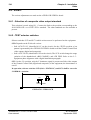
ATTENTION
La carte microprocesseur contient une pile LITHIUM. Il y a danger d'explosion en cas
de remplacement incorrect de la pile.
Remplacer uniquement par une pile de même type ou d'un type équivalent recommandé
par le constructeur.
LITHIUM
BATTERY
+
MICROPROCESSOR UNIT
De façon à éviter tout dommage corporel ou matériel, il est impératif de respecter les
consignes de sécurité suivantes.
PRÉCAUTIONS CORPORELLES
Le dispositif de sectionnement du produit est l’interrupteur bipolaire situé en face avant du
CCU. Pour isoler totalement l'équipement du réseau, il est nécessaire de débrancher le
cordon secteur.
Afin d’éviter tout danger de chocs électriques, ne pas enlever le cordon d’alimentation
assurant la continuité de terre, lorsque le CCU est reliée à un appareil de classe 2 (sans
prise de terre) sous tension.
Cordon d’Alimentation
Utilisez le cordon d’alimentation fourni avec l’équipement.
Surcharges électriques
Respectez la plage de tension spécifiée.
Mise à la Terre
B1707M00LD
Septembre 2000
THOMSON TTV1707 / CCU DT500
Manuel utilisateur
12
CONSIGNES DE SECURITE
Ce produit dispose d’une mise à la terre au travers du cordon d’alimentation. De façon à
éviter tout risque de choc électrique, la broche de mise à la terre doit être correctement
reliée à la terre. Avant toute mise sous tension, assurez-vous que le produit est correctement référencé par rapport à la terre.
Fermeture des Coffrets
De façon à éviter tout risque de feu ou de choc électrique, assurez-vous que le contrôle de
voie est correctement fermé par les plaques d'obturation, les tôles du chassis, etc.
Fusibles
N’utilisez que des fusibles de type et de calibre tels que spécifiés à l’arrière de l’équipement.
Humidité
De façon à éviter tout risque de choc électrique, ne mettez en service le produit qu’en zone
sèche.
Atmosphère Explosive
De façon à éviter tout risque de choc électrique, ne mettez en service le produit qu’en zone
exempte de tout risque d’explosion (atmosphère et matériaux).
Intervention
De façon à éviter tout risque de choc électrique, déconnectez l’alimentation secteur avant
toute intervention dans le coffret.
L'accès aux circuits imprimés internes de l'équipement ne doit être réservé qu'au personnel
technique qualifié. Certaines parties de ces circuits sont à très haute tension électrique. Ce
danger électrique est particulièrement important lorsque le tiroir "CCU POWER" est
extrait du contrôle de voie.
PRÉCAUTIONS MATÉRIELLES
Source d’Alimentation
Respecter le type d’alimentation électrique ainsi que la plage de tension spécifiée sur
l'arrière du CCU.
Encastrement
Pour éviter tout contact électrique dangereux à travers les grilles d’aération et pour parer
toute projection de particules enflammées ou incandescentes provenant de l’intérieur du
coffret, il est demandé d’encastrer le coffret dans une baie.
Ventilation
Pour éviter tout risque de surchauffe, ventilez correctement le produit.
THOMSON TTV1707 / CCU DT500
Manuel utilisateur
B1707M00LD
Septembre 2000
CONSIGNES DE SECURITE
13
Dysfonctionnement suspecté
En cas de doute sur un dommage du produit, procédez à une vérification par un personnel
compétent.
Pour éviter la destruction de certains composants, aucune manipulation de carte enfichable
(extraction ou réinsertion) ne doit être effectuée lorsque l' équipement est sous tension.
Entretien
Nettoyer l'équipement à l'aide d'un chiffon doux et sec ou d'un chiffon doux légèrement
imbibé d'eau savonneuse. Ne jamais utiliser de solvants puissants tels qu'alcool ou
benzine.
Remplacement de composant
N’utilisez que des composants d’origine (ou agréé) THOMSON BROADCAST
SYSTEMS.
Remplacement de Pile
La caméra contient une mémoire sauvegardée par une pile au lithium. Ce composant a une
durée de vie suffisante pour ne jamais être changé. Si, pour une raison quelconque, le
remplacement s’avère nécessaire, il convient de respecter les trois conditions suivantes :
• L’opération ne doit être réalisée que par un personnel qualifié.
• Le composant doit être remplacé par un composant de mêmes caractéristiques.
ATTENTION ! Il y a danger d’explosion s’il y a remplacement incorrect de la
batterie.
• Respectez le sens de montage du composant. La mise au rebut du composant usagé doit
s’effectuer suivant les consignes du fabricant du composant.
B1707M00LD
Septembre 2000
THOMSON TTV1707 / CCU DT500
Manuel utilisateur
14
THOMSON TTV1707 / CCU DT500
Manuel utilisateur
CONSIGNES DE SECURITE
B1707M00LD
Septembre 2000
Chapitre 1 - Spécifications
15
Chapitre 1
Spécifications
1.1 - Principales caractéristiques ........................................ 17
1.1.1 - Contrôle de voie...................................................................................
1.1.2 - Caméra ................................................................................................
1.1.3 - Convertisseurs DC/DC ........................................................................
1.1.4 - Longueur du câble triaxial caméra / contrôle de voie ..........................
17
18
20
21
1.2 - Présentation .................................................................. 22
1.3 - Configuration................................................................. 26
1.4 - Principes généraux d'exploitation............................... 27
1.4.1 - Contrôle de l'équipement à partir d'un pupitre ..................................... 27
1.4.1.1 - Branchement du pupitre sur le contrôle de voie ..............................
1.4.1.2 - Alimentation du pupitre ....................................................................
1.4.1.3 - Liaison SMPTE ................................................................................
1.4.1.4 - Distance contrôle de voie pupitre.....................................................
27
27
27
27
1.5 - Principes généraux de maintenance ........................... 28
B1707M00LD
Septembre 2000
THOMSON TTV1707 / CCU DT500
Manuel utilisateur
16
THOMSON TTV1707 / CCU DT500
Manuel utilisateur
Chapitre 1 - Spécifications
B1707M00LD
Septembre 2000
Chapitre 1 - Spécifications
Principales caractéristiques
17
1.1 - PRINCIPALES CARACTÉRISTIQUES
1.1.1 - Contrôle de voie
Liaisons vidéo :
Caméra
Voie
Voie : numérique 270 Mbits
Caméra : 2 analogiques Bande passante 4,5 Mhz typique
Distance maximum Voie/Pupitre :
30 m avec câble de liaison blindé (liaison RS422 protocole SMPTE)
Signaux d'entrée :
1 Genlock (vidéo BBS) - 2 vidéo retours Voie
Caméra, dont une optionnelle
Signaux de sortie :
3 sorties numériques 270 Mbits - 2 Vidéos codées - 1 sortie microphone caméra
Autres signaux :
1 Interphonie (4fils ou RTS) - Liaisons pupitre SMPTE - Alimentation pupitre - Signalisations ON AIR1 et ON AIR2
Alimentation secteur :
AC 90-135 V/180-270 V 50 ou 60 Hz
Consommation :
Environ 70 W avec caméra et viseur 4 cm sans convertisseur DC/DC externe
Poids :
Environ 7 kg
Dimensions :
Rack 1/2 19" 3U
Environnement :
En fonctionnement : 0°C à +45°C - humidité relative 95 % sans condensation
En stockage : -20°C à +55°C - humidité relative 95 % sans condensation
Compatibilité électromagnétique et sécurités :
Conforme aux directives CE (marquage CE)
B1707M00LD
Septembre 2000
THOMSON TTV1707 / CCU DT500
Manuel utilisateur
18
Chapitre 1 - Spécifications
Principales caractéristiques
1.1.2 - Caméra
Standards :
625/50 PAL, Liaison numérique
525/60 NTSC, Liaison numérique
Capteurs microlentilles (PAL ou NTSC) :
IT 4/3 750 pixels - FIT 4/3 750 pixels (uniquement en PAL) - IT commutable:16/9 4/3
1000 pixels
FIT commutable:16/9 4/3 1000 pixels - FIT commutable:16/9 4/3 1250 pixels
Système optique :
Séparateur à prisme, f/1.4, RGB, comprenant deux roues porte filtres motorisées: Une roue
équipée de 4 filtres de densité (1=Clear, 2=1/4, 3=1/16, 4=1/64) et une roue équipée de
4 filtres d'effet (A=Clear, B=Star 4 , C=Strong Fog, D=Light Fog)
Nota : La roue d'effet et la motorisation des roues sont optionnelles.
Montage de l’optique :
Monture baïonnette standard
Traitement vidéo :
Numérique 12 bits
Rapport Signal /bruit :
Objectif fermé, Niveau du noir = 70 mV, Filtres PH 100 kHz et PB 5 MHz, g = 1,
gain = 0 dB, Contour OFF, Masking OFF => S/B eff sur la luminance > 60 dB en sortie
numérique du contrôle de voie (après conversion D/A)
Sensibilité :
Conditions de test : 0 dB, Blanc 90 % de réflectance, Température de couleur 3200°K,
ouverture d’objectif = f/8, quelque soit le type de CCD = 1600 lux
Taux de modulation à 400 lignes TV (5,1 MHz en 4/3 ou 6,8 MHz en 16/9):
en luminance : > 55 % (Contour OFF) et 100 % après correction (Contour ON).
Superpositions (fonction de l'objectif utilisé) :
Zone 1 : 20 ns - Zone 2 : 30 ns - Zone 3 : 40 ns
Signaux d'entrée :
1 Entrée microphone
THOMSON TTV1707 / CCU DT500
Manuel utilisateur
B1707M00LD
Septembre 2000
Chapitre 1 - Spécifications
Principales caractéristiques
19
Signaux de sortie :
Vidéo monitoring - 2 Vidéos externes dont une optionnelle - Tension "EXT DC OUT" (30
à 52 V) pour convertisseur DC/DC externe optionnel.
Autres signaux :
1 Interphonie microcasque - Connections pour objectif léger
Consommation :
Caméra seule sans viseur et sans objectif: 28 W typique
Caméra seule avec viseur 4 cm et sans objectif : 30,5 W typique
Poids :
Caméra seule avec viseur 4 cm et sans objectif : Environ 5,5 kg
Environnement :
En fonctionnement : -20°C à +45°C - humidité relative 95 % sans condensation.
En stockage : -20°C à +55°C - humidité relative 95 % sans condensation.
Compatibilité électromagnétique et sécurités :
Conforme aux directives CE (marquage CE)
B1707M00LD
Septembre 2000
THOMSON TTV1707 / CCU DT500
Manuel utilisateur
20
Chapitre 1 - Spécifications
Principales caractéristiques
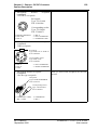
1.1.3 - Convertisseurs DC/DC
Le convertisseur externe DC/DC est fourni en option. Il est alimenté à partir de la tension
non régulée délivrée sur l'embase "DC OUT" de la caméra et se fixe mécaniquement sur la
semelle de la caméra. Son rôle est de délivrer une tension continue pour, par exemple,
alimenter un PROMPTER.
Deux types de convertisseurs peuvent être fournis :
• Un convertisseur avec sortie 13 VDC/50 W.
• Un convertisseur avec sortie 24 VDC/50 W.
NOTA : On ne peut pas connecter simultanément plusieurs convertisseurs sur la caméra.
Tension d'entrée
30 à 52 VDC (+10 %/-20 %)
Tension de sortie
13 VDC (±5 %) ou 24 VDC (±5 %) suivant le type de convertisseur
Puissance maximum de sortie
50 Watts
Poids
environ 0,36 kg
Environnement
En fonctionnement: -20°C à +45°C - humidité relative 95 % sans condensation.
En stockage: -20°C à +55°C - humidité relative 95 % sans condensation.
Compatibilité électromagnétique et sécurités
Conforme aux directives CE (marquage CE)
THOMSON TTV1707 / CCU DT500
Manuel utilisateur
B1707M00LD
Septembre 2000
Chapitre 1 - Spécifications
Principales caractéristiques
21
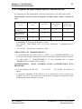
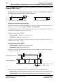
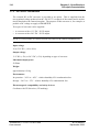
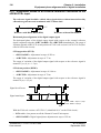
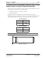
1.1.4 - Longueur du câble triaxial caméra / contrôle de voie
Les longueurs de câble mentionnées ci dessous font référence à un câble sans raccord.
Fonctionnalités assurées suivant la longueur du câble triaxial caméra / contrôle de
voie :
Vidéo et Audios
caméra
Vidéo RET1
Vidéo
PROMPTER/
RET2
Convertisseur
PROMPTER
DC/DC=50 W
0 à 150 mètres
(0 à 90 mètres)
X
X
X
X
150 à 400 mètres
(90 à 240 mètres)
X
X
400 à 500 mètres
(240 à 300 mètres)
X
Longueur de câble
triaxial
• x à x mètres : Triaxial type B (diamètre 13 mm)
Par exemple : Câble Belden 9232 Ø 13,2 mm, atténuation : 3,9 dB/100 mètres à
60 MHz.
• (x à x mètres) : Triaxial type A (diamètre 9 mm)
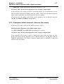
VIDÉO "RET.1" ET "PROMPTER/RET.2" :
• Le fonctionnement des vidéos retours 1 ("RET.1") et 2 ("PROMPTER/RET.2") est
assuré pour une longueur maximum de câble triaxial spécifié dans le tableau ci dessus.
• La vidéo retour 2 ("PROMPTER/RET. 2") n'est disponible que si l'option
"PROMPTER" est installée dans la caméra.
CONVERTISSEUR
PROMPTER :
DC/DC EXTERNE POUR L'ALIMENTATION D'UN
• Les convertisseurs DC/DC 48 V
option.
13 V ou 48 V
24 V (50 W) sont fournis en
• La puissance maximum (50 W) délivrée par le convertisseur externe connecté sur
l'embase "DC OUT" de la caméra est assurée pour une longueur maximum de câble
triaxial spécifié dans le tableau ci dessus.
B1707M00LD
Septembre 2000
THOMSON TTV1707 / CCU DT500
Manuel utilisateur
22
Chapitre 1 - Spécifications
Présentation
1.2 - PRÉSENTATION
Séparateur optique à prismes à grande ouverture (f/1.4)
Le séparateur est équipé de :
• 1 roue porte-filtres de densité à quatre positions.
• 1 roue porte-filtres d'effet à quatre positions.
• 1 Filtre en quartz éliminant les erreurs de colorimétrie dues à la lumière polarisée
réfléchie.
• 1 Filtre optique anti-moiré ("anti-aliasing").
• 1 Filtre infrarouge.
Chaîne de traitement vidéo haute performance
Gain par bonds de -3 dB à +21 dB.
Le traitement vidéo numérique sur 12 bits comporte principalement :
• Correction de taches au noir automatique.
• Correction de taches au blanc.
• Correction de pixels automatique :
La correction de pixels permet de réduire la non uniformité entre pixels. Ce dispositif
corrige les pixels éventuellement devenus défectueux dans le temps.
• Compensation automatique de diffusion de la lumière (FLARE).
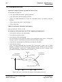
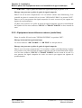
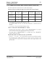
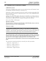
• Correction de contour :
Cette correction comprend une correction dite "d'ouverture" centrée sur 6-7 MHz
destinée à compenser la perte de taux de modulation jusqu'à 6 MHz et une correction
dite "physiologique" centrée sur 3-4 MHz destinée à donner du relief à l'image. Cette
correction est élaborée à partir des trois voies R, V, B.
Détail
Correction
physiologique
Centrage
Correction
d’ouverture
100 %
Sans correction
1
2
3
4
5
6
MHz
Signal vidéo avec corrections de contour et filtre optique passe bas
THOMSON TTV1707 / CCU DT500
Manuel utilisateur
B1707M00LD
Septembre 2000
Chapitre 1 - Spécifications
Présentation
23
Le débruitage des signaux de contour horizontal et de contour vertical est asservi au gain.
Le niveau de la correction de contour final est réduit dans les zones sombres de l'image
pour diminuer la visibilité du bruit. Le système est doté d'un compresseur des détails de
grande amplitude ("SOFT CONTOUR").
• Fonction "DIAG CONTOUR" qui permet en diminuant l'amplitude des fréquences
proches de la sous porteuse de réduire les phénomènes de "CROSS COLOR".
• Fonction "SKIN DETAIL" qui permet de diminuer le niveau de détail sur n'importe
quelle teinte choisie en manuel ou en automatique par l'opérateur.
• Fonction "DFZ" qui permet de diminuer ou d'augmenter le niveau de détail en fonction
de la position du zoom.
• Correction de "MASKING" permettant un réglage de colorimétrie très précis et
l'identité de couleur de toutes les caméras. Trois valeurs de matrice sont mémorisables,
permettant le raccord colorimètrique de la TTV1707 avec d'autres caméras, en gardant
les valeurs de la matrice EBU en référence.
• Correction de "GAMMA" assurant un très bon rendu des zones faiblement éclairées de
l’image. Plusieurs loi de GAMMA sont proposées: Factory, Custom, BBC, CCIR. A
partir d'une loi définie, il est possible de modifier individuellement les corrections de
gamma des 3 primaires R, G, B.
• "BLACK STRETCH" permet en modifiant la réponse de la correction de GAMMA
d'augmenter ou de diminuer le gain dans les noirs sans affecter le reste de l'image.
• Compression dynamique automatique ou manuelle au blanc avec restitution de la
couleur. Ce dispositif permer d'exploiter au maximum toute la gamme de contraste
restituée par les capteurs et la conversion analogique numérique 12 Bits.
• Fonction "ABL" permet d'augmenter le contraste de certaines images (exemple : par
temps de brouillard).
Liaison triaxiale entre la tête de caméra et le Contrôle de voie
Cette liaison transporte les informations suivantes : La vidéo numérique 270 Mbits,
2 Vidéos retours dont une optionnelle, 1 liaison Interphonie, 1 Son "Micro d'ambiance",
les signaux d'asservissement du générateur de base de temps de la caméra, les informations
aller et retour de télécommande et l'énergie pour l'alimentation de la caméra.
B1707M00LD
Septembre 2000
THOMSON TTV1707 / CCU DT500
Manuel utilisateur
24
Chapitre 1 - Spécifications
Présentation
FACILITÉS D'EXPLOITATION
• Codeur dans la tête de caméra pour contrôler sur un moniteur couleur la vidéo de la
caméra.
• Pupitre permettant un accès rapide aux différents réglages d'exploitation.
• Codeur (PAL ou NTSC) dans le Contrôle de Voie.
Viseur et graticule
Le Cadreur peut afficher dans le viseur :
• Une croix centrale.
• Le format commercial.
• Une "BOX" ajustable.
• Des indicateurs de recopie de "ZOOM" et de "FOCUS".
• Des indicateurs de format opposé.
Il peut contrôler sur le viseur les vidéos Y, RET1, RET2 (RET2 étant optionnel).
Scene-file
Ce sont 4 mémoires de réglages d'exploitation accessibles à partir du pupitre qui autorisent des manipulations de stockage, de recopie, de transfert et de rappel de configurations
d'exploitation.
Nota : Les configurations placées en mémoire sont conservées à la mise hors tension de
l'équipement.
Liaisons audio
La chaîne de prises de vues TTV1707 CCUDT500 est équipée :
• d'un interphone reliant le Cadreur au Réalisateur.
La liaison avec la Régie Son peut être réalisée en "4 fils"(Son aller et Son retour sur des
paires distinctes) ou par l'intermédiaire d'un dispositif RTS .
• d'une liaison "Micro d'ambiance".
Le micro peut être de type électrostatique : il est alors alimenté en fantôme sous 48 volts
à l'aide d'une commutation située sur l'arrière de la caméra. Il peut être aussi de type
électrodynamique (position "Fantom Power OFF").
Une atténuation de 20dB est disponible en face arrière de la caméra (Niveau d'entrée
-40 dB ou -60 dB).
Un commutateur placé sur l'arrière de la caméra permet de sélectionner le micro
connecté sur la caméra ou le micro connecté sur l'ensemble déporté (fonctionnement en
configuration "MICROCAM").
Un réglage continu de sensibilité du micro est également accessible sur l'arrière de la
caméra.
THOMSON TTV1707 / CCU DT500
Manuel utilisateur
B1707M00LD
Septembre 2000
Chapitre 1 - Spécifications
Présentation
25
Les niveaux des Sons à destination de la Régie Son peuvent être ajustés en continu entre
-6 dB et +12 dB.
Source "DC OUT" d'alimentation d'un équipement auxiliaire
Une alimentation 30 à 52 VDC est disponible sur l'arrière de la caméra permettant
d'alimenter un convertisseur externe (disponible en option) fixé sur la semelle de la
caméra.
Deux types de convertisseur peuvent être connectés :
• Convertisseur de tension de sortie13 VDC/50 W.
• Convertisseur de tension de sortie 24 VDC/50 W.
NOTA : La puissance maximum (50 W) est assurée pour une longueur maximum de câble
triaxial. Se référer au paragraphe 1.1.4 - Longueur du câble triaxial caméra / contrôle de
voie.
CAMÉRAS ASSOCIÉES
La caméra 1707 s'intègre parfaitement à un environnement de caméras de types TTV1657,
TTV1657D ou 1557D grâce à un système de commande identique.
B1707M00LD
Septembre 2000
THOMSON TTV1707 / CCU DT500
Manuel utilisateur
26
Chapitre 1 - Spécifications
Configuration
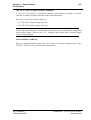
1.3 - CONFIGURATION
OU
Viseur 4 cm
Viseur 14 cm
Viseur 14 cm
•
Monitoring
•
Vidéo retour 1
•
Vidéo retour 2 (option)
•
Interphonie
•
DC OUT
•
Microphone ambiance
•
Interphonie
PRE
VIEW
LOCK
•
•
Convertisseur DC/DC
Liaison RS422
ON AIR 1
ON
AIR 2
ACTIV
CCU STATUS
BARS
SETTING
F1
F2
F3
F4
PRESET
GAIN
FILTERS
DETAIL
STORE
DFZ
BLACK
COLOUR
RECALL
KNEE
SHUTTER
CALL
EXIT
NEXT
CTRL
DIAG
GAMMA
SKIN
OTHER
BLACK BAL WHITE BAL
LIMIT
ASSIGNED
LIMIT
ASSIGNED
GAIN
ASSIGNED
ENABLE
ASSIGNED
BLACK
FINE
AUTO IRIS
ADJUST
EXTENDER
IRIS
BLACK
LEVEL
OCP40
OCP42
ON
•
GEN LOCK
AIR
I
CAMERA
CAM.LOCK
CAM. OK
RCP
MAINS
ON
O
EXT.REF.
•
Vidéo retour 1
•
Vidéo retour 2 (option)
•
Interphonie
•
Signalisations (ON AIR1, 2)
OFF
CABLE
COARSE
•
Vidéo numérique
•
Vidéo composite (PAL ou
NTSC)
•
Interphonie
•
Micro ambiance
OPEN
H
FINE
SC
SC/H
FRONT
PORCH
TRIAX
•
GENLOCK/
SOUND/
CCU
VIDEO
AUX
POWER
Secteur 230 V 50 Hz ou 110 V 60 Hz
CONTRÔLE DE VOIE DT500
THOMSON TTV1707 / CCU DT500
Manuel utilisateur
B1707M00LD
Septembre 2000
Chapitre 1 - Spécifications
Principes généraux d'exploitation
27
1.4 - PRINCIPES GÉNÉRAUX D'EXPLOITATION
L'exploitation complète du pupitre est décrite dans le manuel d’utilisation du
pupitre.
1.4.1 - Contrôle de l'équipement à partir d'un pupitre
1.4.1.1 - Branchement du pupitre sur le contrôle de voie
Le pupitre OCP est raccordé à la prise "REMOTE" du Contrôle de Voie. Il doit fermer la
liaison sur 150 Ω (inverseur situé sur la face arrière du pupitre sur 150 Ω).
1.4.1.2 - Alimentation du pupitre
La tension d'alimentation, d'environ 12 Vdc, doit être fournie par le Contrôle de voie
(embase REMOTE broche 5).
Ne pas utilisé l'embase XLR4 située en face arrière du pupitre.
1.4.1.3 - Liaison SMPTE
Le système d'exploitation utilise le protocole de transmission SMPTE.
1.4.1.4 - Distance contrôle de voie pupitre
La distance maximum est de 100 mètres sous certaines conditions. Se référer au paragraphe 2.8 - Pupitre d’exploitation.
B1707M00LD
Septembre 2000
THOMSON TTV1707 / CCU DT500
Manuel utilisateur
28
Chapitre 1 - Spécifications
Principes généraux de maintenance
1.5 - PRINCIPES GÉNÉRAUX DE MAINTENANCE
Les réglages techniques (soft) de la caméra sont accessibles sous condition à partir des
pupitres OCP40 / OCP42.
Se référer au manuel d’utilisation des pupitres OCP40 / OCP42.
La maintenance de la caméra peut être effectuée avec ou sans contrôle de voie au moyen
d'une carte outil (carte "TOOLS" disponible en option) permettant différentes configurations de la caméra.
Se référer au manuel de maintenance de l'équipement TTV1707 DT500.
THOMSON TTV1707 / CCU DT500
Manuel utilisateur
B1707M00LD
Septembre 2000
Chapitre 2 - Installation
29
Chapitre 2
Installation
2.1 - Montage du contrôle de voie en baie............................................ 31
2.1.1 - Montage du contrôle de voie avec un accessoire 1/2 19" ................... 31
2.1.1.1 - Montage du coffret support accessoire à gauche du contrôle de voie 31
2.1.1.2 - Montage de l'accessoire à droite du contrôle de voie ...................... 33
2.1.2 - Montage de deux contrôles de voie en baie ........................................ 34
2.2 - Alimentation secteur ...................................................................... 36
2.3 - Audio................................................................................................ 37
2.3.1 - Son Ambiance ..................................................................................... 37
2.3.2 - Interphonie........................................................................................... 38
2.4 - Vidéo ................................................................................................ 40
2.4.1 - Sélection du standard de sortie de la vidéo composite ....................... 40
2.4.2 - Commutateurs de test ......................................................................... 40
2.5 - Mise en phase de l'équipement avec une installation de type
numérique................................................................................................ 41
2.5.1 - Equipement asservi sur une référence externe connectée sur l'entrée "GEN
LOCK" ............................................................................................................. 42
2.5.2 - Equipement sans référence externe (mode libre)................................ 43
2.6 - Mise en phase de l'équipement avec une installation de type
analogique ............................................................................................... 44
2.6.1 - Equipement asservi sur une référence externe connectée sur l'entrée "GEN
LOCK" ............................................................................................................. 45
2.6.1.1 - Référence externe avec BLACK BURST......................................... 45
2.6.1.2 - Référence externe sans BLACK BURST......................................... 46
2.6.2 - Equipement sans référence externe (mode libre)................................ 48
2.7 - Adaptation aux commandes externes de signalisations d’antenne
49
2.8 - Pupitre d’exploitation ..................................................................... 50
2.9 - Montage de l'attache câble sur la caméra .................................... 52
B1707M00LD
Septembre 2000
THOMSON TTV1707 / CCU DT500
Manuel utilisateur
30
THOMSON TTV1707 / CCU DT500
Manuel utilisateur
Chapitre 2 - Installation
B1707M00LD
Septembre 2000
Chapitre 2 - Installation
Montage du contrôle de voie en baie
31
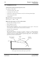
Ce chapitre décrit les généralités d'installation de l'équipement. Pour la description
des différents connecteurs, se référer aux chapitres spécifiques à chaque sous
ensemble. Les pupitres OCP40 / OCP42 font l'objet d'une notice spécifique.
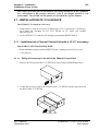
2.1 - MONTAGE DU CONTRÔLE DE VOIE EN BAIE
Le contrôle de voie DT500 se monte dans une baie 19" :
1. Soit seul, soit avec un accessoire de dimension 1/2 19" (vecteurscope, oscilloscope,
etc.) grâce au kit de montage d’un CCU DT500 en baie 19" de référence
BDT05701AA.
2. Soit 2 CCU DT500 côte à côte grâce au kit de référence BDT05700AA.
2.1.1 - Montage du contrôle de voie avec un accessoire 1/2 19"
MATERIEL NECESSAIRE :
• Kit de montage en baie de référence BDT05701AA contenant les divers accessoires.
• Un tournevis.
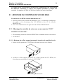
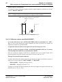
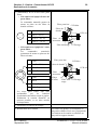
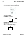
2.1.1.1 - Montage du coffret support accessoire à gauche du contrôle de voie
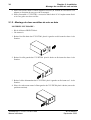
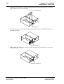
1. Retirer l'oreille gauche du CCU DT500 en dévissant les deux vis de fixation.
CCU
2. Accoller le coffret support accessoire sur le flanc gauche du CCU DT500, les
décrochements positionnés à l'arrière du CCU DT500.
CCU
Coffret support accessoire
B1707M00LD
Septembre 2000
THOMSON TTV1707 / CCU DT500
Manuel utilisateur
32
Chapitre 2 - Installation
Montage du contrôle de voie en baie
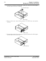
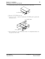
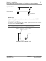
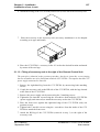
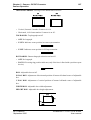
3. Visser les 6 vis Ø 4 avec la clé six pans à partir de l' intérieur du coffret support
accessoire pour le fixer au CCU DT500.
6 vis F/90HC M4x5
CCU
Clé six pans
4. Placer le cache avant contre le flanc gauche du CCU DT500 (une seule position
convient).
CCU
Cache avant
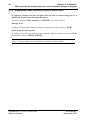
5. Visser les deux vis de Ø 3 avec le tournevis à partir de l'intérieur du coffret support
accessoire pour fixer le cache avant.
CCU
2 vis F/90 M3x4
THOMSON TTV1707 / CCU DT500
Manuel utilisateur
B1707M00LD
Septembre 2000
Chapitre 2 - Installation
Montage du contrôle de voie en baie
33
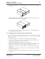
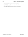
6. Fixer l'oreille gauche du CCU DT500 (démontée en 1) à gauche du coffret support
accessoire.
CCU
7. Placer l'accessoire dans le coffret support accessoire (la fixation de l'accessoire est à
adapter en fonction de son type et de sa marque).
CCU
8. Placer l'ensemble CCU DT500 + accessoire dans la baie 19" à l'emplacement désiré
et le fixer grâce aux deux oreilles.
2.1.1.2 - Montage de l'accessoire à droite du contrôle de voie
Le principe est identique au montage précédent, mais les 6 vis Ø 4 reliant les 2 ensembles
sont à visser à partir de l'intérieur du CCU DT500. Ceci nécessite la dépose du bloc
alimentation du CCU.
1. Retirer l'oreille droite du CCU DT500 en dévissant les deux vis de fixation.
2. Accoller le coffret support accessoire sur le flanc droit du CCU DT500, les
décrochements positionnés à l'avant du CCU DT500.
3. Retirer le bloc alimentation en dévissant ses 3 vis de fixation.
4. Visser les 6 vis Ø 4 avec la clé 6 pans à partir de l' intérieur du CCU DT500 (bloc
alimentation retiré) pour fixer le coffret support accessoire au CCU DT500.
5. Placer le cache avant contre le flanc droit du CCU DT500 (une seule position
convient).
6. Visser les deux vis de Ø 3 avec le tournevis à partir de l'intérieur du CCU DT500
pour fixer le cache avant.
7. Fixer l'oreille droite du CCU DT500 (démontée en 1) à droite du coffret support
accessoire.
B1707M00LD
Septembre 2000
THOMSON TTV1707 / CCU DT500
Manuel utilisateur
34
Chapitre 2 - Installation
Montage du contrôle de voie en baie
8. Placer l'accessoire dans le coffret support accessoire (la fixation de l'accessoire est à
adapter en fonction de son type et de sa marque).
9. Placer l'ensemble CCU DT500 + accessoire dans la baie 19" à l'emplacement désiré
et le fixer grâce aux deux oreilles.
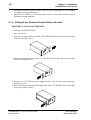
2.1.2 - Montage de deux contrôles de voie en baie
MATERIEL NECESSAIRE :
• Kit de référence BDT05700AA.
• Un tournevis.
1. Retirer l'oreille droite du CCU DT500 placée à gauche en dévissant les deux vis de
fixation.
CCU
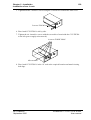
2. Retirer l'oreille gauche du CCU DT500 placé à droite en dévissant les deux vis de
fixation.
CCU
3. Retirer le bloc alimentation du CCU DT500 placé à gauche en dévissant ses 3 vis de
fixation.
4. Placer le cache avant contre le flanc gauche du CCU DT500 placé à droite (une seule
position convient).
CCU
THOMSON TTV1707 / CCU DT500
Manuel utilisateur
B1707M00LD
Septembre 2000
Chapitre 2 - Installation
Montage du contrôle de voie en baie
35
5. Visser les deux vis de Ø 3 avec le tournevis pour fixer le cache avant.
CCU
2 vis F/90 M3x4
6. Placer les 2 CCU DT500 côte à côte.
7. Visser les 6 vis Ø 4
alimentation retiré).
à partir de l' intérieur du CCU DT500 placé à gauche (bloc
6 vis F/90HC M4x5
Clé six pans
CCU
CCU
8. Placer l'ensemble des 2 CCU DT500 dans la baie 19" à l'emplacement désiré et le
fixer grâce aux deux oreilles.
B1707M00LD
Septembre 2000
THOMSON TTV1707 / CCU DT500
Manuel utilisateur
36
Chapitre 2 - Installation
Alimentation secteur
2.2 - ALIMENTATION SECTEUR
ADAPTATION DE L'ÉQUIPEMENT À LA TENSION SECTEUR
En fonction des numéros de série, les alimentations équipant le contrôle de voie peuvent
être :
• Bi tensions (équipées d'une commutation automatique de tension secteur) et aucune
adaptation n'est donc à faire en fonction de la tension secteur. L'équipement est prévu
pour fonctionner de 100 à 125 VAC et de 200 à 240 VAC.
• Ou mono tension et dans ce cas l'équipement est prévu pour fonctionner de 100 à
125 VAC ou de 200 à 240 VAC en fonction du type des alimentations.
Avant de relier l'équipement au secteur, s'assurer de la plage de fonctionnement de
l'équipement, en se référant à l'étiquette située en face arrière du contrôle de voie.
CHANGEMENT DU FUSIBLE
Le fusible est situé dans l'embase secteur en face arrière du contrôle de voie.
Déconnecter la fiche secteur pour accéder au fusible.
Cette embase contient également un fusible de rechange.
Type de fusible :
En 110 V ou 220 V : Valeur T 6,3 AH 250 V Référence:T9000671.
2 fusibles :
• fusible de protection de l’équipement,
• fusible de rechange.
THOMSON TTV1707 / CCU DT500
Manuel utilisateur
B1707M00LD
Septembre 2000
Chapitre 2 - Installation
Audio
37
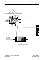
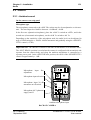
2.3 - AUDIO
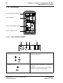
2.3.1 - Son Ambiance
Sur le bandeau arrière de la caméra
Type de microphone
Le microphone connecté sur l'embase "MIC IN" peut être de type électrodynamique ou
électrostatique. Le niveau d’entrée nominal doit être compris entre -60 dB et -40 dB.
Dans le 1er cas (microphone dynamique), placer l'inverseur "0/48 V" sur la position "OFF"
et dans le 2ème cas (microphone électrostatique), placer l'inverseur "0/48 V" sur la position "48 V".
En fonction de la sensibilité du microphone utilisé, le niveau audio peut être ajuster par
bond avec l'atténuateur de 20 dB "-40 dB/-60 dB" et progressivement avec le réglage
"SENSITIVITY" (±5 dB).
Important : Le commutateur "REAR CAM/SPLIT HEAD" doit être en position "REAR
CAM". La position "SPLIT HEAD" est utilisée lorsque la caméra est configurée avec le
bloc d'analyse séparé du corps de caméra et que le microphone ambiance est connecté sur
l'ensemble bloc séparé. En position "SPLIT HEAD" l'action du réglage "SENSITIVITY"
est d'environ ±1 dB.
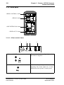
+
1
ON
Réglage fin du niveau
d’entrée microphone
OFF
2
CALL
VIDEO RET
TRIAX
MENU
-
DC OUT
l’entrée
ON
REM
SENSITIVITY
(ON)
REAR CAM
SPLIT HEAD
MIC IN
1
-40dB
Mise en/hors service de
l’alimentation
fantôme
48 V d’alimentaion du
microphone
LEVEL
-60dB
48v
3
Mise en/hors service de
l’atténuateur
20 dB
d’entrée microphone
2
Sélection
de
microphone
CAM
OFF
MONITOR
RET. 1
PROMPTER / RET. 2
Entrée du microphone
d’ambiance
FACE ARRIÈRE DE LA CAMÉRA
B1707M00LD
Septembre 2000
THOMSON TTV1707 / CCU DT500
Manuel utilisateur
38
Chapitre 2 - Installation
Audio
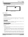
Dans le contrôle de voie
Le niveau de sortie du Son "MICRO AMBIANCE" est réglable sur la carte "SOUND/
AUX" entre -6 dB et +18 dB. Le réglage s'effectue au moyen du commutateur S500 "0 dB
+12 dB" et du potentiomètre R500 "LEVEL".
R500
S500
SOUND / AUX PCB
2.3.2 - Interphonie
Sur le bandeau arrière de la caméra
Micro casque Cadreur
Type de microphone
Le microphone utilisé doit être de type électrostatique avec une sensibilité de -40 dB.
La caméra fournit au microphone par la prise casque-microphone une tension d’alimentation de +9 volts.
Type d'écouteur
Les écouteurs doivent être de type électrodynamique. Le niveau maximum appliqué à
chaque écouteur est de 8 Vcc/300 Ohms.
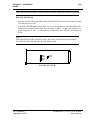
Dans le contrôle de voie
La liaison "INTERPHONIE" contrôle de voie régie peut être du type 4 fils ou RTS/
CLEARCOM.
Liaison 4 fils
• Les commutateurs S560 et S580 sur la carte "SOUND/AUX" du Contrôle de voie
doivent être positionnés sur 4 W.
• Le niveau de sortie du Son "INTERPHONIE" est réglable sur la carte "SOUND/AUX"
du Contrôle de Voie entre -6 dB et +18 dB. Le réglage s'effectue au moyen du
commutateur S540 "0 dB +12 dB" et du potentiomètre R540 "LEVEL".
• Le niveau d'entrée du Son "INTERPHONIE" est réglable sur la carte "SOUND/AUX"
du Contrôle de Voie entre -6 dB et +18 dB. Le réglage s'effectue au moyen du
commutateur S581 "0dB +12dB" et du potentiomètre R580 "LEVEL".
THOMSON TTV1707 / CCU DT500
Manuel utilisateur
B1707M00LD
Septembre 2000
Chapitre 2 - Installation
Audio
39
Nota : Lorsque la liaison 4 fils est utilisée, la liaison interphonie RTS/CLEARCOM est
indisponible.
Liaison RTS/CLEARCOM
• Les commutateurs S560 et S580 doivent être positionnés sur RTS.
• Le niveau d'entrée du Son "INTERPHONIE" RTS est réglable sur la carte "SOUND/
AUX" du Contrôle de Voie entre -6 dB et +18 dB. Le réglage s'effectue au moyen du
commutateur S581 "0 dB +12 dB" et du potentiomètre R580 "LEVEL".
Notas :
Lorsque la liaison RTS/CLEARCOM est utilisée, la liaison interphonie 4 fils est
indisponible.
Le canal RTS/CLEARCOM doit avoir une terminaison de 200 Ω.
S581
R580
S580
S560
R540
S540
SOUND / AUX PCB
B1707M00LD
Septembre 2000
THOMSON TTV1707 / CCU DT500
Manuel utilisateur
40
Chapitre 2 - Installation
Vidéo
2.4 - VIDÉO
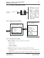
Les différents réglages s'effectuent sur la carte "GENLOCK/VIDEO".
2.4.1 - Sélection du standard de sortie de la vidéo composite
La sélection s'effectue au moyen de J91. Placer le cavalier sur la position correspondant au
standard "PAL BGH 625L" ou "NTSC 525L". Les autres standards ne sont pas disponibles.
2.4.2 - Commutateurs de test
Les commutateurs S170 et S171 permettent différents test de l'équipement :
S170 : Dépend de la version de logiciel de Z160 :
• Logiciel ≤ 47017011/C (identifié 011/C sur le circuit) : En position "TEST", une mire
de barres est générée par la carte "GENLOCK/VIDEO" sur toutes les sorties vidéo du
contrôle de voie (digitales et composites).
• Logiciel ≥ 47017011/D (identifié 011/D sur le circuit) : Le commutateur S170 permet
de modifier la plage d'action des roues codeuses "ΦH COARSE et"FH FINE". Se référer
au paragraphe 2.5 - Mise en phase de l'équipement avec une installation de type
numérique.
S171 : En position "Y", seul le signal de luminance Y est présent sur toutes les sorties
vidéo du contrôle de voie (digitales et composites) de l'équipement, la chrominance est
coupée.
En exploitation, S170 (Logiciel ≤ 47017011/C) et S171 doivent être en position
"NORMAL".
Z160
J91
S170
S171
NTSC
PAL BGH 6251
GENLOCK / VIDEO PCB
THOMSON TTV1707 / CCU DT500
Manuel utilisateur
B1707M00LD
Septembre 2000
Chapitre 2 - Installation
Mise en phase de l'équipement avec une installation de type numérique
41
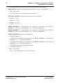
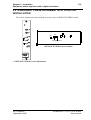
2.5 - MISE EN PHASE DE L'ÉQUIPEMENT AVEC UNE INSTALLATION DE TYPE NUMÉRIQUE
Les différents réglages et commutations s'effectuent sur et en face avant de la carte
"GENLOCK/VIDEO".
CAM.LOCK
Z160
EXT.REF.
J92
COARSE
H
J91
S170
S171
NTSC
PAL BGH 6251
FINE
SC/H
SC
FRONT
PORCH
Commutations carte "GENLOCK/VIDEO"
GENLOCK/
VIDEO
Réglages carte "GENLOCK/VIDEO"
B1707M00LD
Septembre 2000
THOMSON TTV1707 / CCU DT500
Manuel utilisateur
42
Chapitre 2 - Installation
Mise en phase de l'équipement avec une installation de type numérique
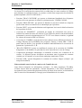
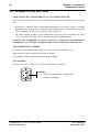
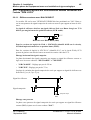
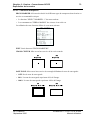
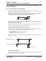
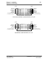
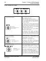
2.5.1 - Equipement asservi sur une référence externe connectée sur
l'entrée "GEN LOCK"
Le signal de référence doit être un signal vidéo au Noir avec ou sans Burst chargé sur
75 ΩΤdélivré par un générateur de qualité broadcast
0,3 V
0,3 V
Référence avec Black Burst (BBS)
0,3 V
Référence sans Black Burst
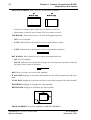
Phasage horizontal du signal numérique
La phase horizontale du signal numérique par rapport au signal de référence externe se
règle avec les roues codeuses "ΦH COARSE" et "ΦH FINE".
La plage d'action des roues codeuses dépend de S170 pour les versions de logiciel de Z160
≥ 47017011/D (identifié 011/D sur le circuit) :
S170 en position haute (FINE) :
• "ΦH COARSE" : Réglage par pas de 592 ns.
• "ΦH FINE" : Réglage par pas de 37 ns.
La plage de variation du signal numérique de sortie par rapport au signal de référence est
d'environ 9,5 µs (-8 µs +1,5 µs).
S170 en position basse (WIDE) :
• "ΦH COARSE" : Réglage par pas de 1184 ns.
• "ΦH FINE" : Réglage par pas de 74 ns.
La plage de variation du signal numérique de sortie par rapport au signal de référence est
d'environ 19 µs (±9.5 µs).
Signal de référence
Signal numérique
E
A
V
S
A
V
S
A
V
E
A
V
S170 : FINE = -8µs à +1,5 µs
S170 : WIDE = ±9.5 µs
REF
Pour les versions de logiciel ≤ 47017011/C (identifié 011/C sur le circuit Z160) :
• S170 commute un signal test de type mire de barres sur toutes les sorties vidéo du CCU.
• "ΦH COARSE" régle la phase horizontale du signal numérique par pas de 592 ns.
THOMSON TTV1707 / CCU DT500
Manuel utilisateur
B1707M00LD
Septembre 2000
Chapitre 2 - Installation
Mise en phase de l'équipement avec une installation de type numérique
43
• "ΦH FINE" : régle la phase horizontale du signal numérique par pas de 37 ns.
Phasage sous porteuse et palier de garde du signal composite
Dans le cas où la sortie composite du CCU est utilisée comme sortie Monitoring, il est
conseillé de placer le cavalier J92 sur la carte "GENLOCK/VIDEO" en position "OFF".
Dans ce cas la sous porteuse du signal composite de sortie est asservie par rapport aux
signaux de synchronisation.
La phase sous porteuse et le palier de garde du signal composite peuvent éventuellement
être ajustés avec les roues codeuses "ΦSC/H" et "FRONT PORCH" en face avant de la
carte.
2.5.2 - Equipement sans référence externe (mode libre)
Placer le cavalier J92 sur la carte "GENLOCK/VIDEO" en position "OFF".
Phasage horizontal du signal numérique
Les roues codeuses "ΦH COARSE" et "ΦH FINE" ne sont pas actives.
Phasage sous porteuse et palier de garde du signal composite
Dans le cas où la sortie composite du CCU est utilisée comme sortie Monitoring, la phase
sous porteuse et le palier de garde du signal composite peuvent éventuellement être ajustés
avec les roues codeuses "ΦSC/H" et "FRONT PORCH" en face avant de la carte. La
sous porteuse du signal composite de sortie est asservie par rapport aux signaux de
synchronisation.
B1707M00LD
Septembre 2000
THOMSON TTV1707 / CCU DT500
Manuel utilisateur
44
Chapitre 2 - Installation
Mise en phase de l'équipement avec une installation de type analogique
2.6 - MISE EN PHASE DE L'ÉQUIPEMENT AVEC UNE INSTALLATION DE TYPE ANALOGIQUE
Les différents réglages et commutations s'effectuent sur et en face avant de la carte
"GENLOCK/VIDEO".
CAM.LOCK
Z160
EXT.REF.
J92
COARSE
H
J91
S170
S171
NTSC
PAL BGH 6251
FINE
SC/H
SC
FRONT
PORCH
Commutations carte "GENLOCK/VIDEO"
GENLOCK/
VIDEO
Réglages carte "GENLOCK/VIDEO"
THOMSON TTV1707 / CCU DT500
Manuel utilisateur
B1707M00LD
Septembre 2000
Chapitre 2 - Installation
Mise en phase de l'équipement avec une installation de type analogique
45
2.6.1 - Equipement asservi sur une référence externe connectée sur
l'entrée "GEN LOCK"
2.6.1.1 - Référence externe avec BLACK BURST
Le cavalier J92 sur la carte "GENLOCK/VIDEO"doit être positionné sur "ON". Dans ce
cas la sous porteuse du signal composite de sortie est asservie par rapport au burst de référence.
Le signal de référence doit être un signal vidéo au Noir avec Burst chargé sur 75 Ω
délivré par un générateur de qualité broadcast (SC/H stable).
0,3 V
0,3 V
Référence avec Black Burst (BBS)
Pour les versions de logiciel de Z160 ≥ 47017011/D (identifié 011/D sur le circuit),
S170 doit impérativement être en position haute (FINE).
Pour les versions de logiciel ≤ 47017011/C (identifié 011/C sur le circuit Z160), S170
permet de générer une mire de barres sur toutes les sorties vidéo du CCU.
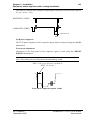
Phasage horizontal du signal composite
La phase horizontale du signal composite par rapport au signal de référence externe se
règle avec les roues codeuses "ΦH COARSE" et "ΦH FINE".
• "ΦH COARSE" : Réglage par pas de 592 ns.
• "ΦH FINE" : Réglage par pas de 37 ns.
La plage de variation du signal composite de sortie par rapport au signal de référence est
d'environ 9,5 µs (-4,5 µs +5 µs).
Signal de référence
Signal composite
-4,5 µs à +5 µs
REF
Phasage sous porteuse
La phase sous porteuse du signal composite de sortie par rapport au signal de référence
externe (BBS) s'ajuste avec la roue codeuse "ΦSC".
B1707M00LD
Septembre 2000
THOMSON TTV1707 / CCU DT500
Manuel utilisateur
46
Chapitre 2 - Installation
Mise en phase de l'équipement avec une installation de type analogique
Palier de garde "Front porch"
Le réglage de la durée du palier de garde avant du signal composite s'effectue avec la roue
codeuse "FRONT PORCH".
Nota : Ce réglage n'agit pas sur la largeur de la suppression horizontale.
PAL 1,5 ±0,3 µs (1,65 µs ±0,1 µs PAL I)
NTSC 1,5 ±0,1 µs
Front porch sorties composites 1 et 2
2.6.1.2 - Référence externe sans BLACK BURST
Le cavalier J92 sur la carte "GENLOCK/VIDEO"doit être positionné sur "OFF".
Dans ce cas la sous porteuse du signal composite de sortie est asservie en interne par
rapport aux signaux de synchronisation.
Le signal de référence doit être un signal vidéo au Noir chargé sur 75 Ω.
Pour les versions de logiciel de Z160 ≥ 47017011/D (identifié 011/D sur le circuit),
S170 doit impérativement être en position haute (FINE).
Pour les versions de logiciel ≤ 47017011/C (identifié 011/C sur le circuit Z160), S170
permet de générer une mire de barres sur toutes les sorties vidéo du CCU.
Phasage horizontal du signal composite
La phase horizontale du signal composite par rapport au signal de référence externe se
règle avec les roues codeuses "ΦH COARSE" et "ΦH FINE".
• "ΦH COARSE" : Réglage par pas de 592 ns.
• "ΦH FINE" : Réglage par pas de 37 ns.
La plage de variation du signal composite de sortie par rapport au signal de référence est
d'environ 9,5 µs (-4,5 µs +5 µs).
THOMSON TTV1707 / CCU DT500
Manuel utilisateur
B1707M00LD
Septembre 2000
Chapitre 2 - Installation
Mise en phase de l'équipement avec une installation de type analogique
47
Signal de référence
Signal composite
-4,5 µs à +5 µs
REF
Phasage SC/H
La phase SC/H du signal composite de sortie s'ajuste avec la roue codeuse "SC/H".
Palier de garde "Front porch"
Le réglage de la durée du palier de garde avant du signal composite de sortie s'effectue
avec la roue codeuse "FRONT PORCH".
Nota : Ce réglage n'agit pas sur la largeur de la suppression horizontale.
PAL 1,5 ±0,3 µs (1,65 µs ±0,1 µs PAL I)
NTSC 1,5 ±0,1 µs
Front porch sorties composites 1 et 2
B1707M00LD
Septembre 2000
THOMSON TTV1707 / CCU DT500
Manuel utilisateur
48
Chapitre 2 - Installation
Mise en phase de l'équipement avec une installation de type analogique
2.6.2 - Equipement sans référence externe (mode libre)
Le signal de référence doit être un signal vidéo au Noir avec Burst chargé sur 75 Ω
délivré par un générateur de qualité broadcast
Les roues codeuses "ΦH COARSE" et "ΦH FINE" ne sont pas actives.
Phasage SC/H
La phase SC/H du signal composite de sortie s'ajuste avec la roue codeuse "SC/H".
Palier de garde "Front porch"
Le réglage de la durée du palier de garde avant du signal composite de sorties'effectue
avec la roue codeuse "FRONT PORCH".
Nota : Ce réglage n'agit pas sur la largeur de la suppression horizontale.
THOMSON TTV1707 / CCU DT500
Manuel utilisateur
B1707M00LD
Septembre 2000
Chapitre 2 - Installation
Adaptation aux commandes externes de signalisations d’antenne
49
2.7 - ADAPTATION AUX COMMANDES EXTERNES DE SIGNALISATIONS D’ANTENNE
Les commandes d’antenne principale "ON AIR 1" et d’antenne secondaire "ON AIR 2"
reçues par le Contrôle de Voie peuvent se présenter sous 2 formes différentes :
• Une tension continue comprise entre +5 volts et +48 volts.
• Une boucle fermée (contact).
L'adaptation s'effectue dans la carte "SOUND/AUX" du contrôle de voie.
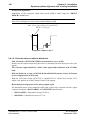
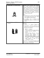
Suivant le type de commande provenant du Mélangeur, placer les commutateurs S800,
S801 (ON AIR 1) et S900, S901 (ON AIR 2) sur les positions indiquées sur la figure
suivante :
Adaptation ON AIR 1
Commande
S800-S801
+5 V à +48 V
Voltage
Boucle
Contact
Adaptation ON AIR 2
Commande
S900-S901
+5 V à +48 V
Voltage
Boucle
Contact
Nota : Les commutateurs S1000 et S1001 ne sont pas utilisés.
S800
S801
S900
S901
S1000
S1001
SOUND / AUX PCB
B1707M00LD
Septembre 2000
THOMSON TTV1707 / CCU DT500
Manuel utilisateur
50
Chapitre 2 - Installation
Pupitre d’exploitation
2.8 - PUPITRE D’EXPLOITATION
Fonction "PREVIEW" :
La présélection d’un équipement à partir d’un pupitre permet d’aiguiller la vidéo de la
chaîne de prise de vues vers les équipements de la salle de Contrôle Technique (Moniteurs,
Oscilloscope de profil, vecteurscope, ...).
Cette présélection s’effectue par appui sur la pédale de présélection ou par appui sur la
paume de la monocommande du pupitre : cela se traduit par une fermeture de boucle entre
les broches 6 et 7 de la prise "PREVIEW/AUX" du pupitre.
L’allumage du voyant "PREVIEW" de ce même pupitre est commandé par un présélecteur
extérieur. Suivant le type de commande d'allumage du voyant (tension ou boucle), le
câblage de la prise connectée sur l'embase "PREVIEW/AUX" du pupitre sera différent.
Se référer au manuel d’utilisation du pupitre OCP40 / OCP42 .
Adaptation d’impédance
Le pupitre doit être fermé sur 150 Ω (Commutateur LOOP/150 Ω situé sur la face
inférieure du pupitre en position 150 Ω).
Alimentation du pupitre
Le pupitre doit être directement alimenté par la câble de la liaison CCU OCP en reliant la
broche 5 du connecteur "REMOTE" du Contrôle de Voie à la broche 5 de l'embase CCU
du pupitre. Les commandes ON AIR1 et ON AIR2 à destination du pupitre et de la caméra
sont superposées à la tension d'alimentation du pupitre. Ne pas utiliser l'embase XLR4 du
pupitre.
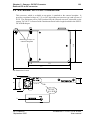
La longueur maximale du câble reliant le pupitre avec le contrôle de voie est de
50 mètres avec un câble 5 paires blindés. Cette longueur maximale est de 100 mètres
si le fil 5 assurant l'alimentation du pupitre est quadruplé. La tresse de masse du
câble doit être reliée aux capots métalliques des connecteurs. Se référer aux schémas
de câblage ci-après.
La masse mécanique du pupitre doit être reliée à la masse mécanique de l'installation.
La liaison est normalement assurée par un câble blindé 5 paires de référence :
• BC041.001 - longueur 1 mètre, ou
• BC041.015 - longueur 15 mètres, ou
• BC041.050 - longueur 50 mètres, ou
• BC042100AA - longueur 100 mètres
THOMSON TTV1707 / CCU DT500
Manuel utilisateur
B1707M00LD
Septembre 2000
Chapitre 2 - Installation
Pupitre d’exploitation
51
CCU
GROUND
GROUND
RETURN A
RETURN B
OUT B
OUT A
GROUND
GROUND
OCP POWER SUPPLY
(+ ON AIR 1, ON AIR 2)
OCP
1
1
6
6
2
2
7
7
3
3
8
8
4
4
9
9
5
5
GROUND
GROUND
OUT A
OUT B
RETURN B
RETURN A
GROUND
GROUND
OCP POWER SUPPLY
(+ ON AIR 1, ON AIR 2)
Tresse de masse du câble
SCHÉMA DES CÂBLES DE 1, 15 OU 50 MÈTRES DE LIAISON CCU OCP
CCU
OCP
1
GROUND
RETURN A
RETURN B
OUT B
OUT A
GROUND
OCP POWER SUPPLY
(+ ON AIR 1, ON AIR 2)
1
6
6
2
2
7
7
3
3
8
8
4
4
9
9
5
5
GROUND
OUT A
OUT B
RETURN B
RETURN A
GROUND
OCP POWER SUPPLY
(+ ON AIR 1, ON AIR 2)
Tresse de masse du câble
SCHÉMA DU CÂBLE 100 MÈTRES DE LIAISON CCU OCP
B1707M00LD
Septembre 2000
THOMSON TTV1707 / CCU DT500
Manuel utilisateur
52
Chapitre 2 - Installation
Montage de l'attache câble sur la caméra
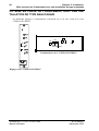
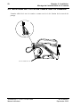
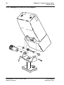
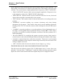
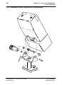
2.9 - MONTAGE DE L'ATTACHE CÂBLE SUR LA CAMÉRA
L'attache câble livré avec la caméra se monte sur la vis de fixation de la courroie de
portage.
3
0
1
2
4
Vers le contrôle de voie
THOMSON TTV1707 / CCU DT500
Manuel utilisateur
B1707M00LD
Septembre 2000
Chapitre 3 - Caméra - Convertisseur DC/DC
53
Chapitre 3
Caméra - Convertisseur DC/DC
3.1 - Description de la caméra ............................................................... 55
3.1.1 - Dimensions, poids ...............................................................................
3.1.2 - Côté droit .............................................................................................
3.1.3 - Côté gauche ........................................................................................
3.1.4 - Face arrière .........................................................................................
55
56
58
60
3.1.4.1 - Cadre "REAR CONTROL" ...............................................................
3.1.4.2 - Cadre "TRIAX" .................................................................................
3.1.4.3 - Cadre "MIC/INTERCOM".................................................................
3.1.4.4 - Cadre "VIDEO OUT"........................................................................
60
62
63
67
3.2 - Convertisseur DC/DC externe........................................................ 68
3.3 - Exploitation de la caméra............................................................... 70
3.3.1 - Commandes cadreur ........................................................................... 70
3.3.2 - Fonctions d'exploitation cadreur .......................................................... 71
3.3.2.1 - Arborescence des fonctions............................................................. 71
3.3.2.2 - Description des fonctions................................................................. 71
3.3.2.3 - Fonctions marqueurs ....................................................................... 73
B1707M00LD
Septembre 2000
THOMSON TTV1707 / CCU DT500
Manuel utilisateur
54
THOMSON TTV1707 / CCU DT500
Manuel utilisateur
Chapitre 3 - Caméra - Convertisseur DC/DC
B1707M00LD
Septembre 2000
Chapitre 3 - Caméra - Convertisseur DC/DC
Description de la caméra
55
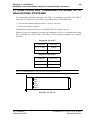
3.1 - DESCRIPTION DE LA CAMÉRA
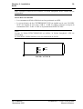
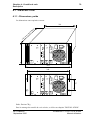
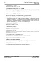
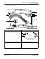
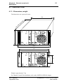
3.1.1 - Dimensions, poids
240
310
Les dimensions sont exprimées en mm.
336
393
Largeur : 127 mm
Poids : Environ 5,5 kg avec viseur 4 cm sans objectif
B1707M00LD
Septembre 2000
THOMSON TTV1707 / CCU DT500
Manuel utilisateur
56
Chapitre 3 - Caméra - Convertisseur DC/DC
Description de la caméra
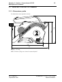
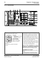
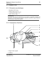
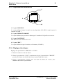
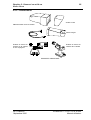
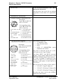
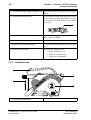
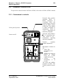
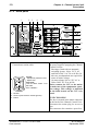
3.1.2 - Côté droit
1
6
7
8
9
2
3
10
11
12
4
13
14
5
1. Embase pour fixation d'accessoires.
2. Embases de fixation du support viseur
14 cm.
Support pour fixation sous la poignée de la caméra
Supports pour fixation
à l’arrière de la camé3. Fixation de la courroie de portage.
4. Identification de la caméra.
La caméra est identifié à l'installation au
moyen des chiffres livrés avec l'équipement.
La fixation sur la caméra est effectuée au
moyen d'un support aimanté.
5. Orifices d'évacuation d'air chaud.
Un ventilateur est fixé derrière ces orifices. Ne pas les obturés.
Le ventilateur est en service pour une température ambiante supérieure à environ 35°C.
THOMSON TTV1707 / CCU DT500
Manuel utilisateur
B1707M00LD
Septembre 2000
Chapitre 3 - Caméra - Convertisseur DC/DC
Description de la caméra
57
6. Fixation de la courroie de portage.
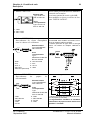
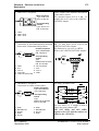
7. Embase "LENS".
Raccordement de l'objectif.
9
8
12
7
Embase
Type : HR-10-10R-12S
Réf : 91.553.055
1
10
2
11
3
6
Prise correspondante
Type : HR-10-10P-12P
Réf : 91.582.124
4
5
1 :Lens Video ext SW IN 7 :Iris Position IN
2 :Lens Start/Stop IN
8 :Lens Iris Auto OUT
3 :-BATT (GND)
9 :Extender IN
4 :5V AUTO Lens OUT 10 :Zoom Position IN
5 :Iris CTRL OUT
11 :Focus Position IN
12 :ON AIR Lens OUT
6 :+12V BATT OUT
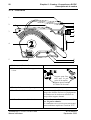
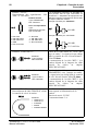
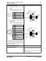
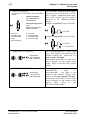
8. Embase "VIEWFINDER".
Raccordement du viseur (4 cm ou 14 cm).
2
1
5
4
3
10
9
8
17 16
15
14
13
20
19
18
7
6
12 11
Embase
Type : DJ-211N-605 SPE.
Réf : 96.103.316
Prise correspondante
Type : EJ-212J-610.
Réf : 96.103.314
1 :VF1 OUT
2 :Video GND
3 :+9,1v OUT
4 :GND
5 :P12v (+12V) OUT
6 :Shield GND
7 :Not connected
8 :Not connected
9 :MISO 1 IN
10 :MOSI 1 OUT
11 :SCK 1 OUT
12 :ON AIR VF OUT
Le cadreur dispose d'une des vidéo
suivantes :
• Y : vidéo luminance
• ENC : vidéo codée
• RET1 : vidéo retour 1
• RET2 : Si l'option "PROMPTER" est
installée dans la caméra.
La vidéo est disponible sur la broche 1 (VF1
OUT),le niveau est de 1 Vcc/75 Ohms.
13 :SS0 8 OUT
La présence des vidéo "RET1" et "RET2"
14 :SS1 8 OUT
(Sportcam)
est conditionnée à la longueur du câble
15 :12V GND
triaxial. Se référer à la partie "SPECIFICA16 :12V GND
TION" de ce manuel.
17 :VF 2 OUT (Cr Color Si un viseur couleur est connecté sur la
VF)
caméra, les vidéo Y, Cr, Cb sont disponibles
18 :VF 2 GND
sur respectivement les broches 1 (VF1
19 :VF 3 OUT (Cb Color
OUT), 17 (VF2 OUT), 19 (VF3 OUT).
VF)
Niveaux sur une mire de barres 75 % en PAL
20 :VF 3 GND
(FULL en NTSC) :
• VF1 OUT : 1Vcc/75 Ohms (Y)
• VF2 OUT : 525 mVcc/75 Ohms (CR)
• VF3 OUT : 525 mVcc/75 Ohms (CB)
Pour la sélection des vidéo, se référer à la
partie EXPLOITATION de ce chapitre.
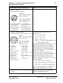
9. Bague de serrage de la colonne support
viseur
B1707M00LD
Septembre 2000
Désserrer cette bague pour permettre le
réglage longitudinal du viseur.
THOMSON TTV1707 / CCU DT500
Manuel utilisateur
58
Chapitre 3 - Caméra - Convertisseur DC/DC
Description de la caméra
10.Colonne support de viseur
Pour désolidariser la colonne du corps de la
caméra, désserrer la bague (9) et tirer la
colonne en la faisant pivoter d'un quart de
tour vers la gauche. (sens de la flèche).
9
11.Bague de serrage du viseur 4 cm.
Dévisser cette bague pour permettre le
réglage latéral du viseur.
12.Bague de serrage de l'objectif.
13.Poussoir de verrouillage de l'épaulière.
Pour déverrouiller l'épaulière, appuyer sur ce
poussoir.
14.Epaulière coulissante.
Pour régler l'épaulière :
• Appuyer sur le poussoir (13).
• Faire glisser l'épaulière.
• Relâcher le poussoir.
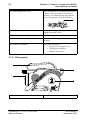
3.1.3 - Côté gauche
1
3
2
4
1. Fixation de la courroie de portage.
THOMSON TTV1707 / CCU DT500
Manuel utilisateur
B1707M00LD
Septembre 2000
Chapitre 3 - Caméra - Convertisseur DC/DC
Description de la caméra
59
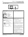
2. Commande(s) de la ou des roues porte
filtres.
• Si la caméra est équipée d'une roue
porte filtres :
La commande manuelle permet de
mettre en place un des filtres de
densité suivants :
4
1
3
2
1:
Clear
2:
1/4 (T = 25 %)
3:
1/16 (T = 6,3 %)
4:
1/64 (T = 1,6 %)
Filtre passe bas CCD bleu
Filtres de
densité
CCD vert
Glace de
protection
Filtre infrarouge
CCD rouge
• Si la caméra est équipée de 2 roues
porte filtres :
Les
commandes
motorisées
permettent de mettre en place un des
filtres suivants :
4
D
Clear
2:
1/4 (T = 25 %)
3:
1/16 (T = 6,3 %)
4:
1/64 (T = 1,6 %)
Glace de
protection
A:
Clear
B:
Star 4
Filtres
d’effets
C:
Strong Fog
D:
Light Fog
1
A
3
C
2
B
Filtre passe bas
1:
CCD bleu
Filtres de densité
CCD vert
Filtre infra- CCD rouge
rouge
Les roues porte filtres sont alors
actionnables
par
les
fonctions
d'exploitation du cadreur ou par le pupitre.
Néanmoins la rotation manuelle est
toujours possible, et est alors assistée
électriquement.
3. Fixation de la courroie de portage.
4. Identification de la caméra.
B1707M00LD
Septembre 2000
La caméra est identifié à l'installation au
moyen des chiffres livrés avec l'équipement.
La fixation sur la caméra est effectuée au
moyen d'un support aimanté.
THOMSON TTV1707 / CCU DT500
Manuel utilisateur
60
Chapitre 3 - Caméra - Convertisseur DC/DC
Description de la caméra
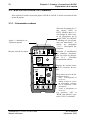
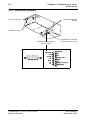
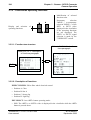
3.1.4 - Face arrière
+
1
Cadre "REAR CONTROL"
ON
CAM
OFF
2
CALL
MENU
VIDEO RET
TRIAX
-
DC OUT
Cadre "TRIAX"
ON
REM
SENSITIVITY
LEVEL
(ON)
REAR CAM
Cadre "MIC/INTERCOM"
SPLIT HEAD
MIC IN
1
-40dB
2
48v
3
-60dB
OFF
MONITOR
Cadre "VIDEO OUT"
RET. 1
PROMPTER / RET. 2
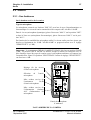
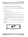
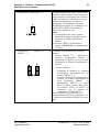
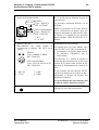
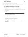
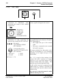
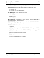
3.1.4.1 - Cadre "REAR CONTROL"
1
2
3
4
+
1
ON
CAM
OFF
2
CALL VIDEO RET
MENU -
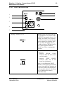
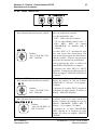
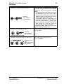
1. Commutateur de mise en (ON) / hors Le voyant associé est allumé lorsque la
(OFF) service de la caméra.
caméra est alimentée.
ON
CAM
OFF
2 Bouton "CALL".
CALL
THOMSON TTV1707 / CCU DT500
Manuel utilisateur
Appel pour attirer l'attention de l'opérateur
du pupitre.
L'appui sur ce bouton allume l'inscription
"CALL" du pupitre d'exploitation.
B1707M00LD
Septembre 2000
Chapitre 3 - Caméra - Convertisseur DC/DC
Description de la caméra
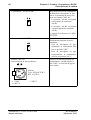
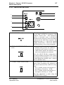
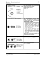
3. Commutateur "VIDEO RET 1-2".
Sélection du numéro de vidéo externe, RET1
ou RET2, affichée dans le viseur lorsque la
vidéo externe est sélectionnée par la touche
"RET" de l'objectif. L'affichage est soit permanent soit momentané (se référer au
paragraphe : Description des fonctions
d'exploitation Cadreur, de ce chapitre). Les
vidéo RET1 et RET2 sont injectées à
l'arrière du contrôle de voie.
Nota :
1) La transmission des vidéo externes
dépend de la longueur du câble triaxial.
Se référer au chapitre SPECIFICATIONS.
2) La vidéo "RET2" est disponible si
l'option "PROMPTER" est installée dans
la caméra.
1
2
VIDEO RET
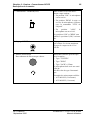
4. Commutateurs
"MENU +, -".
"MENU ↑, ↓"
+
et
Affichage et modification des fonctions
cadreur :
• Touches "MENU ↑, ↓" : Affichent les
fonctions d'exploitation Cadreur et
permettent de déplacer le curseur pour
sélectionner la fonction d'exploitation à
modifier.
•
MENU -
B1707M00LD
Septembre 2000
61
Touches "MENU +, -" :
• Permettent de modifier la fonction
d'exploitation sélectionnée par les
touches "MENU ↑, ↓".
• Si aucune fonction d'exploitation n'est
affichée, ces touches sélectionnent de
façon permanente "MENU -" ou
momentanée "MENU +" le signal
RET1 ou RET2 comme vidéo viseur.
La sélection "RET1" ou "RET2" est
déterminée par la position du
commutateur "VIDEO RET".
Pour connaître le détail des fonctions
d'exploitation se référer au paragraphe 3.3.2
- Fonctions d'exploitation cadreur, de ce chapitre.
THOMSON TTV1707 / CCU DT500
Manuel utilisateur
62
Chapitre 3 - Caméra - Convertisseur DC/DC
Description de la caméra
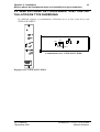
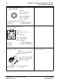
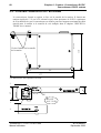
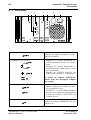
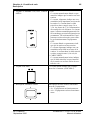
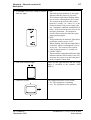
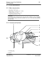
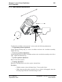
3.1.4.2 - Cadre "TRIAX"
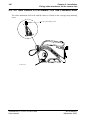
TRIAX
DC OUT
1
2
1. Embase "TRIAX"
Raccordement du câble TRIAXIAL
reliant la caméra au contrôle de voie.
Le câble assure la transmission des différents signaux et l'alimentation de la caméra.
TRIAX
Embases :
-LEMO 75Ω
-LEMO 50Ω
-FISCHER
-KINGS
-DAMAR HAGEN
2 Embase "DC OUT"
La tension délivrée sur cette embase n'est
Raccordement du câble reliant le caméra pas régulée et varie entre 30 VDC et
au convertisseur DC/DC externe.
52 VDC en fonction de :
• La longueur et le type de câble triaxial.
Embase
DC OUT Type: EMD04+Z-ERNC
• La puissance consommée par le
Réf: T9003619
convertisseur DC/DC externe.
4
3
1
2
Prise correspondante
Type: FFA-1S-304-CLAC52
Réf: T9003618
1 : +48V OUT
2 : -5V OUT
3 : GND
4 : GND
Courant maximum sur le 48v = 1,7A
La puissance délivrée sur cette prise varie de
85 W au maximum à 25 W au minimum en
fonction de la longueur et le type de câble
triaxial.
La tension de -5 V permet de retarder le
démarrage du convertisseur DC/DC externe
à la mise sous tension de la caméra afin
d'éviter la disjonction de l'alimentation du
contrôle de voie. Elle ne doit pas être utilisée
en dehors de cette application.
Si l'on branche un convertisseur DC/DC
(même non chargé) sur la caméra en fonctionnement, le système de sécurité fera disjoncter la caméra.
Le raccordement du convertisseur doit se
faire la caméra étant hors tension.
THOMSON TTV1707 / CCU DT500
Manuel utilisateur
B1707M00LD
Septembre 2000
Chapitre 3 - Caméra - Convertisseur DC/DC
Description de la caméra
63
3.1.4.3 - Cadre "MIC/INTERCOM"
ON
REM
1
SENSITIVITY
LEVEL
REAR CAM
2
SPLIT HEAD
-40dB
(ON)
6
7
8
MIC IN
1
3
2
48v
3
-60dB
4
OFF
5
1. Réglage "SENSITIVITY"
SENSITIVITY
2 Commutateur "REAR CAM/SPLIT HEAD"
REAR CAM
SPLIT HEAD
B1707M00LD
Septembre 2000
Réglage fin du niveau de sortie du
son d' ambiance sur l'embase "MIC
OUTPUT" du contrôle de voie. Ce
réglage, accessible avec un tournevis,est fonction de la sensibilité du
micro connecté sur l'embase "MIC
IN". La plage de réglage est de
±5 dB en position "REAR CAM" et
de ±1 dB en position "SPLIT
HEAD" (se référer au paragraphe
suivant).
Sélection de l'entrée du micro
d'ambiance :
• Position
"REAR
CAM" :
L'embase "MIC IN" de la caméra
est sélectionnée.
• Position
"SPLIT
HEAD" :
L'embase "MIC IN" du bloc
séparé est sélectionnée.
Nota : La configuration "SPLIT
HEAD" est une option permettant de
séparer l'ensemble bloc d'analyse du
corps de la caméra afin de disposer
d'un ensemble (objectif + bloc d'analyse) de dimensions réduites
(MICROCAM).
THOMSON TTV1707 / CCU DT500
Manuel utilisateur
64
Chapitre 3 - Caméra - Convertisseur DC/DC
Description de la caméra
3 Commutateur "-40 dB/-60 dB"
-40 dB
-60 dB
Mise en/hors service de l'atténuateur
20 dB d'entrée microphone en fonction de la sensibilité du micro connecté sur l'embase "MIC IN" :
• La position "-40 dB" correspond
à microphone de sensibilité
-40 dB.
• La position "-60 dB" correspond
à un microphone de sensibilité
-60 dB.
Le réglage fin s'effectue avec "SENSITIVITY".
4 Commutateur "48 V/OFF"
48 V
OFF
5 Embase "MIC IN"
Raccordement du micro ambiance
MIC IN
1
3
2
1 : GND
2 : MIC X
Mise en/hors service de la tension
d'alimentation fantôme du micro
d'ambiance :
• Pour un microphone de type
dynamique, le commutateur doit
être en position "OFF".
• Pour un microphone de type
électrostatique, le commutateur
doit être en position "48 V".
S'assurer de la bonne position des
commutateurs "-40 dB/-60 dB" et
"48 V/OFF" en fonction du type de
micro utilisé.
Embase
Type : XLR NC3FD-V
Réf : 91555161
3 : MIC Y
THOMSON TTV1707 / CCU DT500
Manuel utilisateur
B1707M00LD
Septembre 2000
Chapitre 3 - Caméra - Convertisseur DC/DC
Description de la caméra
6 Commutateur "ON/REM/(ON)"
ON
REM
(ON)
65
Mise en/hors service du microphone casque cadreur :
• En position "ON" le microphone
est en service.
• En position "REM" la mise en
service du microphone s'effectue
avec la commande "VTR" de
l'objectif.
• En
position
"(ON)"
microphone est en service.
le
Les positions "ON" et "REM" sont
stables. La position "(ON)" est instable.
7 Réglage "LEVEL"
Réglage du volume sonore du casque cadreur. Le niveau maximum
reçu par le casque est de 8 Vcc/
300 Ω.
LEVEL
8 Embase microcasque
Raccordement du microcasque cadreur.
Différentes embases peuvent équipées la caméra :
• Type "TUCHEL"
• Type "XLR5"
• Type "JACK" 6,35mm
Le microphone doit avoir une sensibilité de
-40 dB et être de type électrostatique.
Exemples de microcasques utilisés :
• AVS 40811H (2 écouteurs)
• AVS 40891H (1 écouteur)
B1707M00LD
Septembre 2000
THOMSON TTV1707 / CCU DT500
Manuel utilisateur
66
Chapitre 3 - Caméra - Convertisseur DC/DC
Description de la caméra
8 Embase microcasque (suite)
Embase "TUCHEL"
Embase
Type : T2121.000
Réf : 91941906
5
6
1
4
2
3
Prise correspondante
Type : T2120.001
Réf : T1000.071
1: RIGHT EARPHONE 4: MIC Y
2: MIC GND
5: LEFT EARPHONE
3: MIC X
6: EARPHONE GND
8 Embase microcasque (suite)
Embase "XLR5"
1
5
4
3
2
Embase
Type : EFD C05+ Z XLR-A3
Réf : T9003628
Prise correspondante
Type : XLR-5-12C
Réf : T1000095
1 : MIC Y
2 : MIC X
3 : GND
4 : LEFT EARPHONE
5 : RIGHT EARPHONE
8 Embase microcasque (suite)
Embase "JACK"
Embase
Type: JACK S2-BBB/BLK
Réf: 91616196
4
5
6
3
2
1
Les contacts 4, 5, 6 de l'embase ne
sont pas connectés.
Prise correspondante
Type: JACK FLJCN
Réf: T1004861
1 :EARPHONE- (GND) 2 :EARPHONE+
MIC - (GND)
3 :MIC +
THOMSON TTV1707 / CCU DT500
Manuel utilisateur
B1707M00LD
Septembre 2000
Chapitre 3 - Caméra - Convertisseur DC/DC
Description de la caméra
67
3.1.4.4 - Cadre "VIDEO OUT"
MONITOR
RET. 1
PROMPTER / RET. 2
1
2
3
1. Embase "MONITOR"
Raccordement d'un moniteur de contrôle.
Sortie vidéo (Niveau : 1 Vcc/75 Ohms) destinée à un moniteur de contrôle.
Les vidéo disponibles sont :
• ENC : Vidéo codée de la caméra.
• VF : La vidéo affichée dans le viseur : Y,
ENC, RET1, RET2 (Si l'option
"PROMPTER" est installée dans la
caméra).
MONITOR
Embase
Type : LX-6P-DLT1-P1
Réf : T1001245
Les vidéo "ENC" et "Y" présentes sur cette
prise sont issues d'un convertisseur D/A
8 bits et sont prévues pour une utilisation en
vidéo de contrôle. Elles ne sont pas destinées à faire des mesures de performance.
Pour la sélection des vidéo, se référer à la
partie EXPLOITATION de ce chapitre.
La présence des vidéo "RET1 et "RET2"
dépend de la longueur du câble triaxial. Se
référer au chapitre "SPECIFICATIONS" de
ce manuel.
2 Embase "RET. 1"
Raccordement d'un moniteur de contrôle.
RET. 1
Sortie de la vidéo externe N°1 injectée à
l'arrière du contrôle de voie sur l'embase
"VIDEO RET 1" (Niveau : 1 Vcc typique /
75 Ohms).
Embase
Type : LX-6P-DLT1-P1
Réf : T1001245
La présence de la vidéo "RET1" dépend de
la longueur du câble triaxial. Se référer au
chapitre "SPECIFICATIONS".
3 Embase "PROMPTER/RET. 2"
Raccordement d'un moniteur de contrôle.
Si l'option "PROMPTER" est installée dans
la caméra, sortie de la vidéo externe N°2
injectée à l'arrière du contrôle de voie sur
l'embase "PROMTER VIDEO RET 2"
(Niveau : 1 Vcc typique / 75 Ohms).
PROMPTER / RET. 2
Embase
Type: LX-6P-DLT1-P1
La présence de la vidéo "PROMPTER/
Réf: T1001245
RET2" dépend de la longueur du câble
triaxial. Se référer au chapitre "SPECIFICATION".
B1707M00LD
Septembre 2000
THOMSON TTV1707 / CCU DT500
Manuel utilisateur
68
Chapitre 3 - Caméra - Convertisseur DC/DC
Convertisseur DC/DC externe
3.2 - CONVERTISSEUR DC/DC EXTERNE
Le convertisseur, fournit en option, se fixe sur la semelle de la caméra. Il fournit une
tension régulée de 13 V (ou 24 V suivant le type) d'une puissance de 50 W. La puissance
de 50 watts délivrée par le convertisseur est assurée pour une longueur maximum de câble
triaxial entre la caméra et le contrôle de voie indiquée dans le chapitre "SPECIFICATIONS" de ce manuel.
110
Vis de fixation sur la semelle
de la caméra
131
177
Les dimensions sont exprimées en mm.
3
17
DC OUT
37
13V / 50W
4
3
1
OU
2
DC OUT
24 V / 50 W
1
DC IN
2
THOMSON TTV1707 / CCU DT500
Manuel utilisateur
B1707M00LD
Septembre 2000
Chapitre 3 - Caméra - Convertisseur DC/DC
Convertisseur DC/DC externe
1. Embase "13 V/50 W" ou "24 V/50 W".
Sortie de la tension régulée.
DC OUT
OU
DC OUT
1
4
3
13V / 50W
2
1 : GND
2 : N.C.
Embase
Type : XLR-4-31
Réf : 91538047
Prise correspondante
Type : XLR-4-12C
Réf : 91647565
3 : N.C.
4 : +V OUT
2 Embase "DC IN".
Raccordement du câble reliant le
convertisseur à l'embase "DC OUT" de la
caméra.
DC IN
4
3
1
2
Embase
Type : EMD04+Z-ERNC
Réf : T9003619
Prise correspondante
Type : FFA-1S-304-CLAC52
Réf : T9003618
1 : +48V IN
2 : -5V IN
3 : GND
4 : GND
69
La tension de sortie en 4 du connecteur est
de 13 ou 24 volts en fonction du type de
convertisseur.
La puissance maximum délivrée est de
50 watts.
Nota : La puissance de 50 watts délivrée
par le convertisseur est assurée pour une
longueur maximum de câble triaxial entre
la caméra et le contrôle de voie spécifiée
dans le chapitre "SPECIFICATION" de ce
manuel.
Alimentation du convertisseur.
La tension reçue sur cette embase varie
entre 30 VDC et 52 VDC en fonction de :
• La longueur et le type de câble triaxial.
• La puissance consommée par le
convertisseur.
La tension de -5 V permet de retarder le
démarrage du convertisseur à la mise sous
tension de la caméra afin d'éviter la disjonction de l'alimentation du contrôle de
voie.
Si l'on branche un convertisseur DC/DC
(même non chargé) sur la caméra en fonctionnement, le système de sécurité fera
disjoncter la caméra.
Le raccordement du convertisseur doit
se faire la caméra étant hors tension.
3
B1707M00LD
Septembre 2000
Voyant allumé : La tension DC OUT est
présente en sortie du convertisseur.
THOMSON TTV1707 / CCU DT500
Manuel utilisateur
70
Chapitre 3 - Caméra - Convertisseur DC/DC
Exploitation de la caméra
3.3 - EXPLOITATION DE LA CAMÉRA
Pour exploiter la caméra à partir du pupitre OCP40 ou OCP42, se référer au manuel d’utilisation du pupitre.
3.3.1 - Commandes cadreur
Appel à destination de
l'opérateur pupitre
+
1
Marche /arrêt de la caméra
ON
CAM
OFF
2
CALL
MENU
VIDEO RET
TRIAX
-
DC OUT
ON
REM
SENSITIVITY
LEVEL
Sélection du numéro de vidéo externe, RET1 ou
RET2, affichée dans le viseur lorsque la vidéo externe est sélectionnée par la
touche "RET" de l'objectif.
L'affichage est soit permanent soit momentané. Se
référer au paragraphe
3.3.2.2 - Description des
fonctions .
Sélection et modification
des fonctions d'exploitation. Se référer au paragraphe 3.3.2 - Fonctions
d'exploitation cadreur.
Réglage du volume sonore
dans les écouteurs du casque.
(ON)
REAR CAM
SPLIT HEAD
Mise en/hors service du microphone casque:
MIC IN
1
-40dB
2
48v
3
-60dB
OFF
MONITOR
RET. 1
PROMPTER / RET. 2
• "ON" : le microphone est
en service.
• "REM" la mise en service
du microphone s'effectue
avec la commande "VTR"
de l'objectif.
• "(ON)" le microphone est
en service.
Les positions "ON" et
"REM" sont stables. La position "(ON)" est instable.
THOMSON TTV1707 / CCU DT500
Manuel utilisateur
B1707M00LD
Septembre 2000
Chapitre 3 - Caméra - Convertisseur DC/DC
Exploitation de la caméra
71
3.3.2 - Fonctions d'exploitation cadreur
• Modification de la valeur
de la fonction sélectionnée.
• Sélection
permanente
"MENU -" ou momentanée
"MENU +" du signal RET1
ou RET2 comme vidéo
viseur si aucune fonction
n'est sélectionnée. La
sélection
"RET1" ou
"RET2" est déterminée par
la position du commutateur
"VIDEO RET".
+
Affichage et sélection des
fonctions
MENU -
3.3.2.1 - Arborescence des fonctions
Se référer au paragraphe 3.3.2.3 Fonctions marqueurs
Se référer au paragraphe 3.3.2.2 Description des fonctions
-
>
>
S
E
P
R G M
L
E
C
T
M A
R K
M A
R
E
E
R
:
-
-
-
1
:
-
-
>
P
R G M
-
-
-
-
-
E
X
I
T
C R O S
P
R G M
M A
R
K
K
E
R
R
2
:
-
-
>
+, -
S
A
O P
V
F↑, F↓
F
M O
E
X
N
T
S
E
L
E
C
T
:
-
-
-
S
E
L
E
C
T
:
-
-
-
S
E
L
E
C
T
:
-
-
-
S
-
M A R K E
-
C E
-
-
N T E
F E
Z O N E
P O S
I
T
-
E
-
F
F
E
C
T
F
I
L
T
E
R
:
-
-
U
T
R
A
L
F
I
L
T
E
R
:
-
-
S
-
-
F O R M A
T
-
-
-
-
:
-
-
-
:
-
-
-
:
-
-
-
T O P
B A
R G R
.
:
-
-
-
B O
B A
R G R
.
:
-
-
-
:
-
-
-
:
-
-
-
T
-
H
N E
R
R
B O X
E
-
P O S
B O X
P O S
B O X
-
V
W
I
H E
D T
I
H
G H
T
:
-
-
-
B O X
:
-
-
-
B O X
:
-
-
-
3.3.2.2 - Description des fonctions
EFFECT FILTER :Commande électrique de la roue d'effets:
• Position A: Clear
• Position B: Star 4
• Position C: Strong fog
• Position D: Light fog
EXT SELECT: Mode de fonctionnement de la touche "RET" de l'objectif:
• PSH: La vidéo "RET1" ou "RET2" est affichée dans le viseur pendant l'appui de la
touche "RET".
• MEM: Un premier appui sur la touche "RET" affiche la vidéo "RET1" ou "RET2" et un
B1707M00LD
Septembre 2000
THOMSON TTV1707 / CCU DT500
Manuel utilisateur
72
Chapitre 3 - Caméra - Convertisseur DC/DC
Exploitation de la caméra
nouvel appui est nécessaire pour revenir à l'affichage de la vidéo caméra.
MON SELECT :Sélection du signal vidéo disponible sur la prise "MONITOR":
• ENC: Vidéo codée
• VF: Vidéo viseur (avec l'incrustation des caractères)
NEUTRAL FILTER :Commande électrique de la roue de densité.
• Position 1: Clear
• Position 2: T=25%
• Position 3: T=6,3%
• Position 4: T=1,6%.
PRGM MARKER 1: Programmation des marqueurs sélectionnés par "SELECT
MARKER : 1" (Se référer au paragraphe 3.3.2.3 - Fonctions marqueurs).
PRGM MARKER 2: Programmation des marqueurs sélectionnés par "SELECT
MARKER : 2" (Se référer au paragraphe 3.3.2.3 - Fonctions marqueurs).
SELECT MARKER: Sélection des marqueurs.
• 0: Aucun marqueur
• 1: Affichage des marqueurs programmés dans "PRGM MARKER 1" (Se référer au
paragraphe 3.3.2.3 - Fonctions marqueurs).
• 2: Affichage des marqueurs programmés dans "PRGM MARKER 2" (Se référer au
paragraphe 3.3.2.3 - Fonctions marqueurs).
• VF SELECT: Sélection du signal vidéo viseur:
• Y: Signal de luminance
• ENC: Vidéo codée
• COL: Y, CR, CB (utilisés avec un viseur couleur).
THOMSON TTV1707 / CCU DT500
Manuel utilisateur
B1707M00LD
Septembre 2000
Chapitre 3 - Caméra - Convertisseur DC/DC
Exploitation de la caméra
73
3.3.2.3 - Fonctions marqueurs
PRGM MARKER 1 :Permet de choisir les différents types de marqueurs dont la mise en
service est commandée soit par:
• La fonction "SELECT MARKER : 1" du menu cadreur.
• Les commutateurs "ZEBRA-MARKS" des viseurs 4 cm ou14 cm.
La validation de cette fonction affiche le sous menu suivant:
-
>
P
R G M
-
-
-
-
-
E
X
I
T
C R O S
S
A
O P
-
S
-
M A R K E
-
C E
-
-
N T E
F E
Z O N E
P O S
I
T
-
E
-
R
S
-
-
-
R
F O R M A
T
-
-
-
-
:
-
-
-
:
-
-
-
:
-
-
-
T O P
B A
R G R
.
:
-
-
-
B O
B A
R G R
.
:
-
-
-
:
-
-
-
:
-
-
-
T
B O X
H
V
W
I
H E
P O S
B O X
P O S
B O X
D T
I
H
G H
T
:
-
-
-
B O X
:
-
-
-
B O X
:
-
-
-
EXIT: Sortie du menu "PRGM MARKERS"
CROSS CENTER: Mise en ou hors service de la croix centrale:
4/3
Center cross
16/9
Center cross
SAFE ZONE: Mise en ou hors service du rectangle délimitant la zone de sauvegarde:
• OFF: Pas de zone de sauvegarde.
• 90%: La zone de sauvegarde représente 90% de l'image.
• 100%: La zone de sauvegarde représente 100% de l'image.
4/3
Safety zone: 90 (or 100%)
B1707M00LD
Septembre 2000
16/9
Safety zone: 90 (or 100%)
THOMSON TTV1707 / CCU DT500
Manuel utilisateur
74
Chapitre 3 - Caméra - Convertisseur DC/DC
Exploitation de la caméra
OPPOSITE FORMAT: Mise en service de deux traits pointillés:
4/3
16/9
Opposite format
Opposite format
• Verticaux servant de repère format 4/3 si la caméra est en 16/9.
• Horizontaux servant de repère format 16/9 si la caméra est en 4/3.
TOP BARGR. : Mise en/hors service et choix du bargraph supérieur:
• OFF: Pas de bargraph
• Z.CEN: Indication de la position du zoom en représentation centrée:
• Z.LEF: Indication de la position du zoom en représentation à gauche:
BOT BARGR.: Mise en/hors service et choix du bargraph inférieur:
• OFF: Pas de bargraph.
• FOCUS: Indicateur de la position de la bague de mise au point (seulement si l'objectif
est équipé d'une recopie de position):
BOX: Mise en ou hors service du cadre ajustable.
H. POS. BOX: Réglage de la position horizontale du coin inférieur gauche du cadre ajustable.
V. POS. BOX: Réglage de la position verticale du coin inférieur gauche du cadre ajustable.
WIDTH BOX: Réglage de la largeur du cadre ajustable.
HEIGHT BOX: Réglage de la hauteur du cadre ajustable.
WIDTH
HEIGHT
V. POS.
H. POS.
PRGM MARKER 2:(Fonctions identiques au PRGM MARKER1).
THOMSON TTV1707 / CCU DT500
Manuel utilisateur
B1707M00LD
Septembre 2000
Chapitre 3 - Caméra - Convertisseur DC/DC
Exploitation de la caméra
75
Permet de choisir les différents types de marqueurs (MARK2) dont la mise en service est
commandée soit par:
• La fonction "SELECT MARKER : 2" du menu cadreur.
• Les commutateurs "ZEBRA-MARKS" des viseurs 4 cm ou 14 cm.
B1707M00LD
Septembre 2000
THOMSON TTV1707 / CCU DT500
Manuel utilisateur
76
THOMSON TTV1707 / CCU DT500
Manuel utilisateur
Chapitre 3 - Caméra - Convertisseur DC/DC
Exploitation de la caméra
B1707M00LD
Septembre 2000
Chapitre 4 - Contrôle de voie
77
Chapitre 4
Contrôle de voie
4.1 - Description ...................................................................................... 79
4.1.1 - Dimensions, poids ............................................................................... 79
4.1.2 - Face arrière ......................................................................................... 80
4.1.3 - Face avant ........................................................................................... 84
B1707M00LD
Septembre 2000
THOMSON TTV1707 / CCU DT500
Manuel utilisateur
78
THOMSON TTV1707 / CCU DT500
Manuel utilisateur
Chapitre 4 - Contrôle de voie
B1707M00LD
Septembre 2000
Chapitre 4 - Contrôle de voie
Description
79
4.1 - DESCRIPTION
4.1.1 - Dimensions, poids
Les dimensions sont exprimées en mm.
39
0
(a
ve
cc
on
ne
ct
eu
rs
)
218
ON AIR
I
CAMERA
CAM.LOCK
CAM. OK
RCP
EXT.REF.
MAINS
ON
O
OFF
CABLE
OPEN
COARSE
H
FINE
SC/H
SC
FRONT
PORCH
GENLOCK/
VIDEO
TRIAX
SOUND/
AUX
CCU
POWER
264
246
ON AIR
I
CAMERA
CAM.LOCK
CAM. OK
RCP
EXT.REF.
OFF
CABLE
OPEN
COARSE
H
FINE
SC
MAINS
ON
O
57
SC/H
FRONT
PORCH
TRIAX
GENLOCK/
VIDEO
SOUND/
AUX
CCU
POWER
Poids: Environ 7Kg
Pour le montage du contrôle de voie en baie, se référer au chapitre "INSTALLATION".
B1707M00LD
Septembre 2000
THOMSON TTV1707 / CCU DT500
Manuel utilisateur
80
Chapitre 4 - Contrôle de voie
Description
4.1.2 - Face arrière
1
2
3
4
5
6
T6,3A H 250V
INPUT
REMOTE
CAMERA
VIDEO RET 1
7
PROMPTER
VIDEO RET 2
8
GENLOCK
EXT. REF.
9
N
TALLY
OUTPUT
INTERCOM
1
MIC OUTPUT
DATA + DC OUT
53V
3A MAX
COMPOSITE
V. B. S.
2
SERIAL DIGITAL OUTPUT
1
2
2
3
10
11
3
1
1. Embase secteur et fusibles.
Raccordement du câble secteur
N
1
2
3
2 fusibles:
• Fusible de protection de
l'équipement.
• Fusible de rechange
Type de fusible:
En 110V ou 220V:
Valeur T 6,3 AH 250V
Référence:T9000671.
1 : Neutre
2 : Terre (relié à la masse mécanique)
3 : Phase
En fonction des numéros de série, les alimentations équipant le contrôle de voie peuvent être:
• Bi tensions (équipées d'une commutation automatique de tension secteur) et
aucune adaptation n'est donc à faire en
fonction de la tension secteur. L'équipement est prévu pour fonctionner de 100 à
125V AC et de 200 à 240V AC.
• Ou mono tension et dans ce cas l'équipement est prévu pour fonctionner de 100 à
125V AC ou de 200 à 240V AC en fonction du type des alimentations.
Avant de relier l'équipement au secteur,
s'assurer de la plage de fonctionnement de
l'équipement, en se référant à l'étiquette située en face arrière du contrôle de voie.
CHANGEMENT DU FUSIBLE
Déconnecter la fiche secteur pour accéder au
fusible.
Le fusible est situé dans l’embase secteur qui
contient également un fusible de rechange.
THOMSON TTV1707 / CCU DT500
Manuel utilisateur
B1707M00LD
Septembre 2000
Chapitre 4 - Contrôle de voie
Description
81
2. Embase "MIC OUT"
Embase mâle
Type: XLR-3-32
Réf: 91.355.161
2
MIC OUTPUT
Sortie Audio provenant du micro ambiance
connecté sur la caméra.
Le niveau nominal de sortie est de 0dB.
Pour modifier ce niveau, se référer au chapitre "INSTALLATION".
3
Prise
correspondante
Type: XLR-3-11C
Réf: 91.355.160
1
1 : GND
2 : MIC X OUT
3 : MIC Y OUT
3. Embase "INTERCOM".
Raccordement du réseau d'interphonie
entre le cadreur et le réalisateur.
5
INTERCOM
9
Embase femelle
Type: DEP09S400T
Réf: T9001515
1
6
Prise
correspondante
Type:
PMD2T09+Z-HE5-M2
Réf: 99.155.568
1 : GND
2 : IN Y
3 : OUT X
4 : CH1 RTS
5 : CH2 RTS (Not used)
REMOTE
9
1 : GND
2 : RETURN A2
3 : GO B2
4 : GND
5 : PV RC
B1707M00LD
Septembre 2000
1
6
1
6
5
INTERCOM
9
6 : Not connected
7 : IN X
8 : OUT Y
9 : GND
4. Embase "REMOTE".
Raccordement
du
télécommande.
5
Les niveaux nominaux d 'entrée et de sortie
sont de 0dB. Pour modifier ces niveaux, se référer au chapitre "INSTALLATION".
La liaison peut être de type "4fils" ou de type
"RTS". Se référer au chapitre "INSTALLATION".
YX
YX
IN
OUT
CH1
RTS
La liaison est de type RS422:
pupitre
de
Embase femelle
Type: DEP09S400T
Réf: T9001515
Prise
correspondante
Type:
PMD2T09+Z-HE5-M2
Réf: 99.155.568
6 : GND
7 : RETURN B2
8 : GO A2
9 : GND
CCU
OCP
2
7
RETURN A
RETURN B
8
3
OUT A
4
GROUND
5
PV RCP
OUT B
La tension "PV RCP" de 12V permet l'alimentation du pupitre (Pmax=6W).
Les signalisations "ON AIR1" et "ON AIR2"
à destination du pupitre et de la caméra sont
ajoutées à "PV RCP".
THOMSON TTV1707 / CCU DT500
Manuel utilisateur
82
Chapitre 4 - Contrôle de voie
Description
Les signalisations "ON AIR1" et "ON AIR2" re5. Embase "TALLY".
Raccordement des signalisations "ON çues peuvent être de type "VOLTAGE" ou
"CONTACT". L'adaptation de l'équipement aux
AIR1" et "ON AIR2".
Embase femelle
Type: DEP09S400T
Réf: T9001515
9
5
TALLY
6
différents types de commande est décrite dans
le chapitre "INSTALLATION".
Exemple: ON AIR1 par "CONTACT":
1
1 : Not used
2 : ON AIR1 NEG
3 : ON AIR2 POS
4 : GND
5 : Not connected
Prise correspondante
Type:
PMD2T09+Z-HE5-M2
Réf: 99.155.568
6 : Not used
7 : ON AIR1 POS
8 : ON AIR2 NEG
9 : Not connected
9
TALLY
ON AIR1
6
Embases
VIDEO RET 1 Type: P2189-A
Réf: T9003306
7. Embases "PROMPTER VIDEO RET 2".
Embases
PROMPTER
Type: P2189-A
VIDEO RET 2
Réf: T9003306
8. Embase "TRIAX"
Raccordement du câble TRIAXIAL reliant
le contrôle de voie à la caméra.
CAMERA
Embases:
• LEMO 75 Ω
• LEMO 50 Ω
• FISCHER
• KINGS
• DAMAR HAGEN
THOMSON TTV1707 / CCU DT500
Manuel utilisateur
1
Exemple: ON AIR1 par "VOLTAGE":
9
5
TALLY
6
6. Embases "VIDEO RET 1".
5
1
U
+
-
ON AIR1
U=5 à 48Volts
Entrée de la vidéo retour N° 1 avec "passage en sonde". Le signal n'est pas chargé
dans le contrôle de voie. Niveau d'entrée :
1Vcc/75 Ohms.
La transmission de la vidéo "RET 1" à la
caméra dépend de la longueur du câble
triaxial.
Se
référer
au
chapitre
"SPECIFICATIONS".
Entrée de la vidéo retour N° 2 (ou
"PROMPTER") avec "passage en sonde".
Le signal n'est pas chargé dans le contrôle
de voie. Niveau d'entrée: 1Vcc/75 Ohms.
La transmission de la vidéo "RET 2" à la
caméra dépend de la longueur du câble
triaxial.
Se
référer
au
chapitre
"SPECIFICATIONS".
Le câble assure la transmission des différents signaux et l'alimentation de la
caméra.
Tension de sortie: 52 VDC
Courant maximum: 3 A
B1707M00LD
Septembre 2000
Chapitre 4 - Contrôle de voie
Description
9. Embases "GEN LOCK EXT. REF.".
GENLOCK
EXT. REF.
Embases
Type: P2189-A
Réf: T9003306
10.Embases "COMPOSITE V.B.S.".
COMPOSITE
V. B. S.
1
2
1
2
B1707M00LD
Septembre 2000
Entrée du signal de référence avec "passage
en sonde". Le signal n'est pas chargé dans le
contrôle de voie. Niveau d'entrée: 1Vcc/75
Ohms.
• En règle générale, le signal doit être du type
"BLACK BURST" pour avoir un asservissement du signal numérique et du signal composite en sortie du contrôle de voie (J92 sur
la carte "GENLOCK/VIDEO"=ON).
• Si le signal de référence ne comporte pas de
"BURST", positionner le cavalier J92 sur la
carte "GENLOCK/VIDEO" en position OFF.
La sous porteuse du signal composite est
alors asservie par rapport au signaux de
synchronisation du signal composite.
Se référer au chapitre "INSTALLATION" pour la
mise en phase de l'équipement.
Sorties du signal codé PAL ou NTSC. Niveaux:
1Vcc/75 Ohms.
Embases
Type: P2189-A
Réf: T9003306
11.Embases "SERIAL DIGITAL OUTPUT".
SERIAL DIGITAL OUTPUT
83
Sorties du signal numérique série
4:2:2 , 270Mbits.
Embases+câble
3 Type:
98230x-021-009.0
Réf: T6000091
THOMSON TTV1707 / CCU DT500
Manuel utilisateur
84
Chapitre 4 - Contrôle de voie
Description
4.1.3 - Face avant
2
1
3
4
5
6
7
ON AIR
I
CAMERA
CAM.LOCK
CAM. OK
RCP
MAINS
ON
O
EXT.REF.
OFF
CABLE
OPEN
COARSE
H
FINE
SC
SC/H
FRONT
PORCH
GENLOCK/
VIDEO
TRIAX
1. Voyany«CAM OK»
CCU
POWER
Ce voyant normalement allumé, indique la
présence du signal numérique en provenance de la caméra.
CAM. OK
2. Réglages«H, SC, SC/H»
COARSE
H
FINE
SC
SOUND/
AUX
SC/H
• Réglages de la phase Horizontale des
vidéos numériques en sortie de l’équipement.
• Réglages des phases Horizontales et
Sous Porteuse des vidéo codées en sortie
de l’équipement.
• Réglage du «FRONT PORCH» des
vidéo codées en sortie de l’équipement..
FRONT
PORCH
Se référer au chapitre «INSTALLATION» pour une description complète
des réglages.
3. Voyants «CAM LOCK, EXT. REF»
• CAM LOCK: Ce voyant normalement
allumé, indique que la caméra est asservie au contrôle de voie.
• EXT REF.: Ce voyant allumé indique la
présence d’un signal de synchronisation
externe sur l’embase "GEN LOCK" du
contrôle de voie.
CAM.LOCK
EXT.REF.
4. Voyant «RCP»
RCP
THOMSON TTV1707 / CCU DT500
Manuel utilisateur
Ce voyant allumé indique la présence d’un
pupitre sur l’embase «REMOTE» du contrôle de voie.
B1707M00LD
Septembre 2000
Chapitre 4 - Contrôle de voie
Description
5. Voyants «CAMERA: ON, OFF, CABLE
OPEN»
CAMERA
ON
OFF
CABLE
OPEN
6. Voyant «ON AIR»
85
• ON:
Ce voyant normalement allumé en permanence indique que la caméra est sous
tension.
Ce voyant, clignotant, indique une consommation trop importante au niveau de
la caméra. Le courant dans le câble
triaxial est alors compris entre 3A et
3,3A. Au dessus de 3,3A l’alimentation
du contrôle de voie disjoncte. Le réarmement s’effectue automatiquement 4 fois.
Si la surcharge persiste la disjonction est
permanente. Un arrêt/marche de l’équipement est alors nécessaire pour remettre en fonctionnement l’équipement.
• OFF:
Ce voyant allumé en permanence indique que la caméra est hors tension.
Ce voyant clignotant, indique une consommation trop faible au niveau de la
caméra. Le courant dans le câble triaxial
est alors compris entre 0,1A et 0,4A
• CABLE OPEN:
Ce voyant normalement éteint, indique
que le câble triaxial n’est pas connecté
sur la caméra ou en face arrière du contrôle de voie.
Ce voyant allumé indique que l’équipement est à l’antenne («ON AIR1»).
ON AIR
7. Interrupteur «MAINS» switch
I
MAINS
Interrupteur de mise en/hors fonctionnement de l’équipement
• «I»: L’équipement en fonctionnement.
• «O»: L’équipement est hors fonctionnement.
O
B1707M00LD
Septembre 2000
THOMSON TTV1707 / CCU DT500
Manuel utilisateur
86
THOMSON TTV1707 / CCU DT500
Manuel utilisateur
Chapitre 4 - Contrôle de voie
Description
B1707M00LD
Septembre 2000
Chapitre 5 - Viseurs 4 cm et 14 cm
87
Chapitre 5
Viseurs 4 cm et 14 cm
5.1 - Viseur 4 cm...................................................................................... 89
5.1.1 - Principales caractéristiques .................................................................
5.1.2 - Commandes et fonctions .....................................................................
5.1.3 - Signalisations lumineuses ...................................................................
5.1.4 - Réglages électriques ...........................................................................
5.1.5 - Cablage de la prise de raccordement du viseur ..................................
5.1.6 - Réglages mécaniques .........................................................................
89
89
91
91
92
93
5.2 - Viseur 14 cm.................................................................................... 94
5.2.1 - Principales caractéristiques .................................................................
5.2.2 - Accessoires .........................................................................................
5.2.3 - Description générale............................................................................
5.2.4 - Description des commandes ...............................................................
5.2.5 - Montage du viseur sur son support .....................................................
B1707M00LD
Septembre 2000
94
95
96
97
98
THOMSON TTV1707 / CCU DT500
Manuel utilisateur
88
THOMSON TTV1707 / CCU DT500
Manuel utilisateur
Chapitre 5 - Viseurs 4 cm et 14 cm
B1707M00LD
Septembre 2000
Chapitre 5 - Viseurs 4 cm et 14 cm
Viseur 4 cm
89
5.1 - VISEUR 4 CM
5.1.1 - Principales caractéristiques
•
•
•
•
•
Résolution: 700 TV lines.
Signal d’entrée: 1Vcc/1kΩ.
Tension d’alimentation: 9,1 Volts .
Consommation: 2,5 W environ.
Poids: environ 0,72Kg.
ATTENTION!
Pour éviter tout risque de destruction, ne pas exposer cet appareil à la pluie ou à
l’humidité.A cause de la présence de hautes tensions à l’intérieur, le capot ne doit être
démonté que par du personnel qualifié.
5.1.2 - Commandes et fonctions
1
2
3
4
5
PEAK
12
CONT
BRIGHT
6
7
8
9
11
10
1. Bague de mise au point
2. Oeilleton
B1707M00LD
Septembre 2000
THOMSON TTV1707 / CCU DT500
Manuel utilisateur
90
Chapitre 5 - Viseurs 4 cm et 14 cm
Viseur 4 cm
3. Potentiomètre "AUDIO"
Non utilisé avec une caméra TTV1707.
4. Commutateur "LOW-TALLY OFF HIGH"
Cet inverseur à trois positions permet le choix entre deux intensités lumineuses et l'inhibition du voyant extérieur "ON AIR 1" situé en face avant du viseur. Ce commutateur n'a
aucune action sur l'indication "ON AIR 1" visible dans le viseur.
5. Commutateur "ZEBRA -MARK"
Inverseur à trois positions (à retour automatique en position centrale).
Seule la position "MARK" est utilisée avec une TTV1707:
• A la première pression vers "MARK" s'affiche les marqueurs 1, à la deuxième pression
s'affiche les marqueurs 2, et à la troisième pression l'affichage s'éteint. Le contenu des
marqueurs est programmable dans les fonctions d'exploitation cadreur. Se référer au
chapitre 3 paragraphe 3.3.2 - Fonctions d'exploitation cadreur.
6. Potentiomètre "BRIGHT"
Réglage de LUMIÈRE du viseur.
7. Potentiomètre "CONT"
Réglage de CONTRASTE du viseur.
8. Potentiomètre "PEAK"
Réglage de renforcement des transitions de l’image sur l’écran du viseur, afin de faciliter
les réglages de mise au point.
9. Verrou de sécurité de fixation du viseur
Pour désolidariser le viseur de la caméra tirer le verrou vers le bas.
10.Queue d'arronde femelle de fixation du viseur
11.Bague de verrouillage du doublet
Pour extraire le doublet tourner la bague dans le sens indiqué sur le dessin et tirer.
12.Voyant ON AIR 1
Ce voyant s'allume lorsque la caméra est à l'antenne (ON AIR 1).
THOMSON TTV1707 / CCU DT500
Manuel utilisateur
B1707M00LD
Septembre 2000
Chapitre 5 - Viseurs 4 cm et 14 cm
Viseur 4 cm
91
5.1.3 - Signalisations lumineuses
1
4
2
BAT
3
1. Voyant "PREVIEW"
Ce voyant s'allume lorsque la caméra est en préparation (ON AIR 2) avant de passer à
l'antenne ON AIR 1.
2. Voyant "HORS STANDARD"
Ce voyant s'allume pour prévenir le cadreur que l' extender de l'objectif est en service.
3. Voyant "BATTERIE"
Non utilisé avec une caméra TTV1707.
4. Voyants "REC"
Ce voyant s'allume lorsque la caméra est à l'antenne (ON AIR 1).
5.1.4 - Réglages électriques
Réglages des potentiomètres "BRIGHT" et "CONT":
1. Mettre la caméra en "mire de barres".
2. Mettre le potentiomètre "CONT" au minimum et régler le potentiomètre "BRIGHT"
pour être à la limite de visibilité de la barre la plus sombre de la mire.
3. Régler le potentiomètre "CONT" pour voir toutes les barres de la mire, sans
saturation de la barre la plus blanche.
B1707M00LD
Septembre 2000
THOMSON TTV1707 / CCU DT500
Manuel utilisateur
92
Chapitre 5 - Viseurs 4 cm et 14 cm
Viseur 4 cm
5.1.5 - Cablage de la prise de raccordement du viseur
2
1
4
5
8
9
10 11 12
13 14
15 16 17
18
6
7
3
19 20
Prise côté contact
1 : VF1 IN (Video)
2 : Video GND
3 : +9,1v IN
4 : GND
5 : Reserved
6 : Shield GND
7 : Audio Control VTR
(Not Used with 1707)
8 : Not connected
9 : MISO 1 OUT
10 : MOSI 1 IN
THOMSON TTV1707 / CCU DT500
Manuel utilisateur
11 : SCK 1 IN
12 : ON AIR VF IN
13 : SS0 8 IN
14 : Not connected
15 : Not connected
16 : Not connected
17 : Not connected
18 : Not connected
19 : Not connected
20 : Not connected
B1707M00LD
Septembre 2000
Chapitre 5 - Viseurs 4 cm et 14 cm
Viseur 4 cm
93
5.1.6 - Réglages mécaniques
2
1
Pour adapter le viseur à la vue de l’opérateur, procéder aux réglages suivants :
• Réglage de la position longitudinale
Desserrer la molette de blocage (1) du viseur et déplacer l’ensemble viseur. Resserrer la
molette.
• Réglage de la position transversale
Desserrer la molette de blocage (2) du viseur et déplacer à droite ou à gauche l’ensemble
viseur. Resserrer la molette.
• Réglage de la position bas - haut
Abaisser ou relever l’oculaire.
• Réglage de mise au point
Tourner la bague de mise au point pour déplacer la lentille interne à l’oculaire.
Procédure :
• Avec la caméra, viser un objet lointain. Ajuster la mise au point.
• Tout en observant avec l’oeil gauche laissé libre le même objet, tourner la bague de
mise au point pour que l’image dans le viseur soit nette.
B1707M00LD
Septembre 2000
THOMSON TTV1707 / CCU DT500
Manuel utilisateur
94
Chapitre 5 - Viseurs 4 cm et 14 cm
Viseur 14 cm
5.2 - VISEUR 14 CM
5.2.1 - Principales caractéristiques
•
•
•
•
•
•
•
Résolution: 600 TV lines.
Signal d’entrée: 1Vcc/1KΩ ou 75Ω (commutable).
Tension d’alimentation: 11 Volts à 17 Volts.
Consommation: 12 W environ avec signal vidéo et voyants d’antenne allumés.
Dimensions: 290x148x134mm.
Géométrie et linéarité: ligne <3%, trame <2%.
Poids: environ 3Kg
ATTENTION!
Pour éviter tout risque de destruction, ne pas exposer cet appareil à la pluie ou à
l’humidité.
A cause de la présence de hautes tensions à l’intérieur, le capot ne doit être démonté
que par du personnel qualifié.
THOMSON TTV1707 / CCU DT500
Manuel utilisateur
B1707M00LD
Septembre 2000
Chapitre 5 - Viseurs 4 cm et 14 cm
Viseur 14 cm
95
5.2.2 - Accessoires
Visière courte
Câble de liaison avec la caméra
Visière longue
Fixation du viseur sur
l’arrière de la caméra
ou sur la poignée
Fixation du viseur sur
l’arrière de la caméra
SUPPORTS ORIENTABLE
B1707M00LD
Septembre 2000
THOMSON TTV1707 / CCU DT500
Manuel utilisateur
96
Chapitre 5 - Viseurs 4 cm et 14 cm
Viseur 14 cm
5.2.3 - Description générale
Voyants "ON AIR 1"
Pattes de fixation du
support
Fixation du capot
Commutateur 1KΩ/75Ω
(à positionner sur 75Ω)
Embase de raccordement
vers la caméra
1
2
3
4
5
6
7
8
9 10 11 12 13 14 15
THOMSON TTV1707 / CCU DT500
Manuel utilisateur
VIDEO GND
SCK
ON AIR1
N.C.
MISO
N.C.
N.C.
9
10
11
12
13
14
15
1
2
3
4
5
6
7
8
VIDEO IN
N.C.
N.C.
SS (Slave Select)
MOSI
N.C.
POWER IN (11V/17V)
POWER GND
B1707M00LD
Septembre 2000
Chapitre 5 - Viseurs 4 cm et 14 cm
Viseur 14 cm
97
5.2.4 - Description des commandes
PEAK
ZEBRA
ON AIR 1
CONT ON AIR BRIGHT
MARK
ON AIR 2
OFF
1
2
3
4
5
6
7
1. Commutateur "ZEBRA MARK"
Inverseur à trois positions (à retour automatique en position centrale).
Seule la position "MARK" est utilisée avec une TTV1707:
• A la première pression vers "MARK" s'affiche les marqueurs 1, à la deuxième pression
s'affiche les marqueurs 2, et à la troisième pression l'affichage s'éteint. Le contenu des
marqueurs est programmable dans les fonctions d'exploitation cadreur (Se référer au
chapitre 3 paragraphe 3.3.2 - Fonctions d'exploitation cadreur).
2. Potentiomètre "PEAK"
Réglage de renforcement des transitions de l’image sur l’écran du viseur, afin de faciliter
les réglages de mise au point.
3. Voyant "ON AIR 1"
Ce voyant s'allume lorsque la caméra est à l'antenne ("ON AIR 1").
4. Potentiomètre "CONT"
Réglage de CONTRASTE du viseur.
5. Commutateur "ON AIR"
Mise en/hors service des voyants "ON AIR" situés sur la capot du viseur.
6. Potentiomètre "BRIGHT"
Réglage de LUMIÈRE du viseur.
7. Voyant "ON AIR 2"
Ce voyant s'allume lorsque la caméra est en préparation avant de passer à l'antenne.
B1707M00LD
Septembre 2000
THOMSON TTV1707 / CCU DT500
Manuel utilisateur
98
Chapitre 5 - Viseurs 4 cm et 14 cm
Viseur 14 cm
5.2.5 - Montage du viseur sur son support
THOMSON TTV1707 / CCU DT500
Manuel utilisateur
B1707M00LD
Septembre 2000
SECTION 2 - English version
99
SECTION 2 - ENGLISH VERSION
CONTENTS
SAFETY INSTRUCTIONS ............................................................... 103
CHAPTER 1
SPECIFICATIONS ........................................................................... 109
1.1 - Principal characteristics............................................. 111
1.1.1 - Channel Control Unit.............................................................
1.1.2 - Camera ...................................................................................
1.1.3 - DC-to-DC converters .............................................................
1.1.4 - Length of the triaxial cable Camera/Channel Control Unit
111
112
114
115
1.2 - Presentation ................................................................ 116
1.3 - Configuration............................................................... 120
1.4 - General principles of use ........................................... 121
1.4.1 - Equipment monitoring from a control panel....................... 121
1.5 - General maintenance principles ................................ 122
CHAPTER 2
INSTALLATION ............................................................................... 123
2.1 - Installation of ccu in rack ........................................... 125
2.1.1 - Installation of a Channel Control Unit with a 1/2 19" accessory
125
2.1.2 - Fitting of two Channel Control Units in the rack ................ 128
2.2 - Mains power supply .................................................... 130
2.3 - Audio ............................................................................ 131
B1707M00LD
September 2000
THOMSON TTV1707 / CCU DT500
User manual
100
SECTION 2 - English version
2.3.1 - Ambient sound ...................................................................... 131
2.3.2 - Intercom ................................................................................. 132
2.4 - Video............................................................................. 134
2.4.1 - Selection of composite video output standard .................. 134
2.4.2 - TEST selector switches ........................................................ 134
2.5 - Equipment phase alignment with a digital
installation............................................................................ 135
2.5.1 - Equipment slaved to an external reference connected to the
«GENLOCK» input............................................................................ 136
2.5.2 - Equipment without external reference (free mode) ........... 137
2.6 - Equipment phase alignment with a analog installation..
138
2.6.1 - Equipment slaved to an external reference connected to the
«GENLOCK» input............................................................................ 139
2.6.2 - Equipment without external reference (free mode) ........... 142
2.7 - Adaptation of channel control unit to external signal controls from the antenna......................................................... 143
2.8 - Operator’s control panel............................................. 144
2.9 - Fitting cable attachment on the camera side............ 146
CHAPTER 3
CAMERA - DC/DC CONVERTER .................................................... 147
3.1 - Camera Description..................................................... 149
3.1.1 - Dimensions and weight ........................................................
3.1.2 - Right-hand side .....................................................................
3.1.3 - Left-hand side........................................................................
3.1.4 - Back panel .............................................................................
149
150
152
154
3.2 - External DC-to-DC converter...................................... 161
3.3 - Camera Operation ...................................................... 163
THOMSON TTV1707 / CCU DT500
User manual
B1707M00LD
September 2000
SECTION 2 - English version
101
3.3.1 - Cameraman’s controls.......................................................... 163
3.3.2 - Cameraman operating functions ......................................... 164
CHAPTER 4
CHANNEL CONTROL UNIT ............................................................ 169
4.1 - Description .................................................................. 171
4.1.1 - Dimensions, weight............................................................... 171
4.1.2 - Back panel.............................................................................. 172
4.1.3 - Front panel ............................................................................. 176
CHAPTER 5
4 CM/14 CM VIEWFINDERS ........................................................... 179
5.1 - 4 cm Viewfinder ........................................................... 181
5.1.1 - Main characteristics ..............................................................
5.1.2 - Controls and functions .........................................................
5.1.3 - Light signals ..........................................................................
5.1.4 - Electrical adjustments ..........................................................
5.1.5 - Viewfinder plug wiring ..........................................................
5.1.6 - Mechanical adjustments .......................................................
181
181
183
183
184
185
5.2 - 14 cm Viewfinder ......................................................... 186
5.2.1 - Main characteristics ..............................................................
5.2.2 - Accessoires ...........................................................................
5.2.3 - General description...............................................................
5.2.4 - Description of controls .........................................................
5.2.5 - Installation of the viewfinder on its mounting ....................
B1707M00LD
September 2000
186
187
188
189
190
THOMSON TTV1707 / CCU DT500
User manual
102
THOMSON TTV1707 / CCU DT500
User manual
SECTION 2 - English version
B1707M00LD
September 2000
SAFETY INSTRUCTIONS
103
SAFETY INSTRUCTIONS
B1707M00LD
September 2000
THOMSON TTV1707 / CCU DT500
User manual
104
THOMSON TTV1707 / CCU DT500
User manual
SAFETY INSTRUCTIONS
B1707M00LD
September 2000
SAFETY INSTRUCTIONS
105
WARNING
The Microprocessor board is fitted with a LITHIUM battery. There is a danger of
explosion if the battery is replaced by an incorrect type.
Only replace by a battery of identical type or an approved equivalent.
LITHIUM
BATTERY
+
MICROPROCESSOR UNIT
To prevent physical or material damage, the following safety instructions must be
complied with.
PHYSICAL PRECAUTIONS
The product isolating device is the two-pole switch on the front of the CCU. For totaly
isolated the equipement from the mains, it's necessary to disconnect the mains cord.
To prevent any danger of electric shocks, do not disconnect the power cord providing
ground continuity when the CCU is connected to a powered class 2 equipment (without
grounding connector).
Power Supply cord
Use the cord supplied with the equipment.
Electrical overloads
Respect the specified voltage.
B1707M00LD
September 2000
THOMSON TTV1707 / CCU DT500
User manual
106
SAFETY INSTRUCTIONS
Grounding
This product is grounded through the power cord. To avoid any risks of electric shock, the
grounding pin must be correctly connected to ground. Prior to applying power, make sure
that the product is correctly referenced with respect to ground.
Closing of units
To prevent any risk of electric shock or fire, make sure that the channel control unit is
properly closed by means of its blanking plates, chassis cover plates, etc.
Fuses
Use only fuses of the type and rating specified on the back of the equipment.
Humidity
To avoid any risk or electric shock, use the product in dry areas only.
Explosive atmosphere
To avoid any risk of electric shock, use the product only in areas free of any risk of explosion (atmosphere and materials).
Intervention
To avoid any risk of electric shock, disconnect the mains prior to performing any work on
the unit. All works hall be performed by qualified personnel.
Access to the equipment internal printed circuit must be reserved for qualified technical
personnel only. Some parts of these circuits are at very high electrical voltages. This electrical hazard is particularly important when the “CCU POWER” unit is extracted from the
Channel Control Unit.
MATERIAL PRECAUTIONS
Power Source
Use the correct type of power source. The voltage range is specified on the CCU rear
panel.
Flush-mounting
To prevent dangerous electric contact between ventilation grids, and to prevent projection
of incandescent or burning particles from the inside of the unit, the unit should be built into
a rack.
Ventilation
To prevent risks of overheating, ventilate the product correctly.
THOMSON TTV1707 / CCU DT500
User manual
B1707M00LD
September 2000
SAFETY INSTRUCTIONS
107
Suspected malfunction
If in doubt concerning damage to the product, have a check performed by a competent
person.
Cleaning
Clean the equipment with a soft dry cloth or a soft dry cloth slightly moistened with soapy
water. Never use powerful solvents such as alcohol or benzene.
To prevent destruction of some of the components, do not handle plug-in printed circuit
boards (connection or disconnection) with the equipment under power.
Component replacement
Use only THOMSON BROADCAST SYSTEMS original (or approved) components.
Replacing the battery
The camera contains a memory safeguarded by a lithium battery. The service life of this
battery is sufficient not to require its replacement. If for any reason replacement is considered necessary, the following conditions must be complied with:
• The operation is to be performed only by qualified personnel.
• The component must be replaced by another component of the same characteristics.
CAUTION: There is a risk of explosion if the battery is incorrectly replaced.
• Respect the component fitting direction. Scrapping of used component shall be made
according to the components manufacturer’s instructions.
B1707M00LD
September 2000
THOMSON TTV1707 / CCU DT500
User manual
108
THOMSON TTV1707 / CCU DT500
User manual
SAFETY INSTRUCTIONS
B1707M00LD
September 2000
Chapter 1 - Specifications
109
Chapter 1
Specifications
1.1 - Principal characteristics............................................. 111
1.1.1 - Channel Control Unit .........................................................................
1.1.2 - Camera ..............................................................................................
1.1.3 - DC-to-DC converters .........................................................................
1.1.4 - Length of the triaxial cable Camera/Channel Control Unit.................
111
112
114
115
1.2 - Presentation ................................................................ 116
1.3 - Configuration............................................................... 120
1.4 - General principles of use ........................................... 121
1.4.1 - Equipment monitoring from a control panel ....................................... 121
1.4.1.1 - Connection of panel to the Channel Control Unit...........................
1.4.1.2 - Panel power supply........................................................................
1.4.1.3 - SMPTE link ....................................................................................
1.4.1.4 - Channel Control Unit to panel distance .........................................
121
121
121
121
1.5 - General maintenance principles ................................ 122
B1707M00LD
September 2000
THOMSON TTV1707 / CCU DT500
User manual
110
THOMSON TTV1707 / CCU DT500
User manual
Chapter 1 - Specifications
B1707M00LD
September 2000
Chapter 1 - Specifications
Principal characteristics
111
1.1 - PRINCIPAL CHARACTERISTICS
1.1.1 - Channel Control Unit
Video links
Camera
Channel Control Unit: 270 Mbits digital
Channel Control Unit
Camera: 2 analog links, Bandpass 4.5 MHz typical
Channel Control Unit / Panel maximum distance:
30 m with screened cable (RS422 SMPTE protocol link)
Input signals:
1 Genlock (BBS video) - 2 return videos Channel Control Unit
Camera (one optional)
Output signals:
3 digital outputs 270 Mbits - 2 encoded videos - 1 camera microphone output
Other signals:
1 Intercom (4-wire or RTS) - SMPTE panel - Power supply - ON AIR1 and ON AIR2
indications
Mains supply:
90 - 135 V / 180-270 V 50 or 60 Hz AC
Consumption:
Approximately 70 W with camera and 4 cm viewfinder without external DC-to-DC
converter
Weight:
Approximately 7 kg
Dimensions:
1 / 2 19" 3U rack
Environment:
In operation: 0°C to + 45°C - relative humidity 95% condensation-free
Storage: - 20°C to + 55°C - relative humidity 95% condensation-free
Electromagnetic compatibility and safety devices:
Conform with CE directives (CE marking)
B1707M00LD
September 2000
THOMSON TTV1707 / CCU DT500
User manual
112
Chapter 1 - Specifications
Principal characteristics
1.1.2 - Camera
Standards:
PAL 625/50, Digital link
NTSC 525/60, Digital link
Microlens sensors (PAL or NTSC):
IT 4/3 750 pixels - FIT 4/3 750 pixels (PAL only) - Switchable IT: 16/9 4/3 1000 pixels
Switchable FIT: 16/9 4/3 1000 pixels - switchable FIT: 16/9 4/3 1250 pixels
Optical system:
Prism f/1.4 RGB separator with two motor-driven filter wheels. One wheel fitted with 4
density filters (1=Clear, 2=1/4, 3=1/16, 4=1/64) and a wheel with 4 effect filters (A=Clear,
B=Star 4, C=Strong Fog, D=Light Fog)
Note: The effect wheel and wheel drive are optional.
Fitting the optical system:
Standard bayonet mounting
Video processing:
12-bit digital
Signal-to-noise ratio:
Lens closed, Black level = 70 mV, 1000 kHz PH filters and 5 MHz PB filter, g = 1, gain =
0 dB, Contour OFF, Masking OFF => S/N rms on luminance > 60 dB at Channel Control
Unit digital output (after digital-to-analog conversion)
Sensitivity:
Test conditions: 0 dB, White 90% reflectance. Colour temperature 3200°K,
lens aperture = f/8, whatever the type of CCD=1600 lux
Modulation depth at 400 TV lines (5.1 MHz for 4/3 or 6.8 MHz for 16/9):
for luminance: > 55% (Contour OFF) and 100% after correction (Contour ON).
Superpositions (depending on lens used):
Area 1: 20 ns - Area 2: 30 ns - Area 3: 40 ns
Input signals:
1 microphone input
THOMSON TTV1707 / CCU DT500
User manual
B1707M00LD
September 2000
Chapter 1 - Specifications
Principal characteristics
113
Output signals:
Video monitoring - 2 External videos (one optional) - “ DC OUT” voltage (30 to 52 V)
used by optional external DC-to-DC converter
Other signals:
1 mic-headset intercom - Connections for light lens
Consumption:
Camera alone without viewfinder and without lens: typical 28 W
Camera alone with 4 cm viewfinder and without lens: 30.5 W typical
Weight:
Camera alone with 4 cm viewfinder and without lens: Approximately 5.5 kg
Environment:
In operation: - 20°C to + 45°C - relative humidity 95% condensation-free
Storage: - 20°C to + 55°C - relative humidity 95% condensation-free
Electromagnetic compatibility and safety devices:
Conforms with CE directives (CE marking)
B1707M00LD
September 2000
THOMSON TTV1707 / CCU DT500
User manual
114
Chapter 1 - Specifications
Principal characteristics
1.1.3 - DC-to-DC converters
The external DC-to-DC converter is provided as an option. This is supplied from the
non-regulated voltage produced on the “DC OUT” receptacle of the camera and is mechanically attached to the camera baseplate. The purpose of this converter is, for example, to
produce a DC voltage to supply a PROMPTER.
Two types of converter can be supplied:
• A converter with a 13 V DC / 50 W output.
• A converter with a 24 V DC / 50 W output.
NOTE: It is not possible to connect several converters to the camera simultaneously.
Input voltage
30 to 52 V DC (+10%/-20%)
Output voltage
13 V DC (± 5%) or 24 V DC (± 5%) depending on type of converter
Maximum output power
50 Watts
Weight:
approximately 0.36 kg
Environment:
In operation: - 20°C to + 45°C - relative humidity 95% condensation-free
Storage: - 20°C to + 55°C - relative humidity 95% condensation free.
Electromagnetic compatibility and safety devices:
Conforms with CE directives (CE marking)
THOMSON TTV1707 / CCU DT500
User manual
B1707M00LD
September 2000
Chapter 1 - Specifications
Principal characteristics
115
1.1.4 - Length of the triaxial cable Camera/Channel Control Unit
The cable length under-mentioned refer to a cable without adapter
Functions ensured according the length of the triaxial cable Camera/Channel:
Camera Video
Audios
RET1 Video
PROMPTER/RE
T2 Video
PROMPTER
CONVERTER
DC/DC=50W
0 to 150 metres
(0 to 90 metres)
X
X
X
X
150 to 400 metres
(90 to 240 metres)
X
X
400 to 500 metres
(240 to 300 metres)
X
Triaxial cable
length
• x to x metres: Type B triaxial cable (diameter 13 mm)
For example: Belden 9232 dia. 13.2 mm cable, attenuation: 3.9 dB/100 metres at
60 MHz
• (x to x metres): Type A triaxial cable (diameter 9 mm)
"RET.1" VIDEO AND "PROMPTER/RET.2" VIDEO:
• Operation of the return videos 1 (“RET.1”) and 2 (“PROMPTER/RET.2”) is ensured
with a maximum triaxial cable length detailed in the previous table.
• The return video 2 (“PROMPTER/RET.2”) is available only if the “PROMPTER”
option is fitted to the camera.
PROMPTER SUPPLY EXTERNAL DC/DC CONVERTER:
• The 48 V
13 V or 48 V
24 V (50 W) DC/DC converters are provided as an option.
• The maximum power (50W) produced by the external converter connected on the
camera "DC OUT"is ensured with a maximum triaxial cable length detailed in the
previous table.
B1707M00LD
September 2000
THOMSON TTV1707 / CCU DT500
User manual
116
Chapter 1 - Specifications
Presentation
1.2 - PRESENTATION
Wide aperture prism type optical separator (f/1.4)
The separator is fitted with:
•
A 4-position density filter wheel.
• A 4-position effect filter wheel.
• 1 quartz filter, suppressing colorimetric errors due to reflected polarised light.
• 1 anti-aliasing optical filter.
• 1 infrared filter.
High performance video processing chain
Gain in steps of - 3 dB to + 21 dB.
Digital video processing over 12 bits consists mainly:
• Automatic Black Shading Correction.
• White Shading Correction.
• Automatic pixel correction:
Pixel correction is intended to reduce non-uniformity between pixels. This device
corrects the pixels which may have become defective with time.
• Automatic flare compensation.
• Contour correction:
This correction includes a correction of “aperture” centred on 6-7 MHz intended to
compensate for the loss in modulation depth up to 6 MHz, and a “physiological”
correction centred on 3-4 MHz intended to provide image relief. This correction is
generated by the three R,G,B channels.
detail
Physiological
correction
Aperture
correction
centring
100 %
1
2
3
4
5
6
MHz
Video signal with contour and lowpass optical filter
THOMSON TTV1707 / CCU DT500
User manual
B1707M00LD
September 2000
Chapter 1 - Specifications
Presentation
117
Noise suppression on the horizontal and vertical contour signals is gain controlled. The
final contour correction level is reduced in the dark areas of the image to decrease noise
visibility. The system features a high amplitude detail compressor (“SOFT CONTOUR”).
• “DIAG CONTOUR” function which, by decreasing the amplitude of frequencies close
to the subcarrier, reduces the “CROSS COLOR” phenomena.
• “SKIN DETAIL” function which is used to reduce the detail level on any skin detail
chosen either manually or automatically by the operator.
• “DFZ” function. This is used to reduce or increase the detail level according to the zoom
position.
• “MASKING” correction enabling very accurate colorimetry and colour identity
adjustment for all cameras. Three matrix values may be stored enabling colorimetric
blending of the TTV1707 with other cameras while retaining the reference EBU matrix
values.
• “GAMMA” correction providing a very good rendering of lowly illuminated areas of
the image. Several gamma laws are proposed: Factory, Custom, BBC, CCIR. From a
given law, it is possible to modify the gamma corrections of the three primaries R, G
and B individually.
• “BLACK STRETCH” by modifying the gamma correction response, black stretch is
used to increase or decrease the black gain without affecting the remainder of the image.
• Automatic or manual white knee with colour restoration. This device is used to obtain
maximum exploitation of the complete contrast range restored by the sensors and 12-bit
analog-to-digital conversion.
• “ABL” function used to increase the contrast of some images (e.g.: in fog).
Triaxial link between the camera head and the Channel Control Unit.
This link carries the following signals: The 270 Mbit digital video, 2 return videos (one
optional), 1 intercom link, 1 “ambient mic” sound, the camera time base generator control
signal, the remote control forward and return signals and power to supply the camera.
B1707M00LD
September 2000
THOMSON TTV1707 / CCU DT500
User manual
118
Chapter 1 - Specifications
Presentation
OPERATING FACILITIES
• Encoder in camera head to monitor camera video on a colour monitor.
• Panel allowing fast access to the various operating adjustments.
• Encoder (PAL or NTSC) in Channel Control Unit.
Visor and graticule
The Cameraman can display the following in the viewfinder:
• a centre cross,
• the commercial format,
• an adjustable “BOX”,
• “ZOOM” and “FOCUS” repeat indicators,
• opposite format indicators.
The Cameraman can monitor the Y, RET1, RET2 videos in the viewfinder (RET2 is
optional).
Scene file
These are 4 operational setting memories accessible from the panel enabling storage,
repeat, transfer and configuration retrieval operations.
Note: The configurations stored are conserved when the equipment is switched off.
Audio links
The TTV1707 CCUDT500 camera system is fitted with:
• an intercom connecting the Cameraman to the producer.
The link with the sound engineer can be of the 4-wire type (outward-going and return
sound over separate pairs) or via an RTS device.
• a “Ambient microphone” link
• The microphone may be electrostatic; if so, it is supplied with phantom 48 Volts via a
selector switch located on the back of the camera. This may also be electrodynamics
(“Phantom Power OFF” position).
• An attenuation of 20 dB is available on the back of the camera (input level - 40 dB or 60 dB).
A selector switch on the back of the camera is used to select the microphone connected
to the camera or that connected to the remoted system (operation in “MICROCAM”
configuration).
Continuous adjustment of microphone sensitivity is also available on the back of the
camera
The sound levels to the Sound Engineer can be continuously adjusted over - 6 dB to
+ 12 dB.
THOMSON TTV1707 / CCU DT500
User manual
B1707M00LD
September 2000
Chapter 1 - Specifications
Presentation
119
“DC OUT” source to supply auxiliary equipment
A 30 to 52 V DC supply is available on the back of the camera to supply an external
converter (available as option) attached to the camera baseplate.
Two types of converter can be connected:
• 13 V DC/50 W output voltage converter
• 24 V DC/50 W output voltage converter.
NOTE: The maximum power (50W) produced by the converter is ensured with a maximum
triaxial cable length. Refer to the 1.1.4 - Length of the triaxial cable Camera/Channel
Control Unit paragraph.
ASSOCIATED CAMERAS
Due to an identical control system, the 1707 camera can be fully integrated into a type
TTV1657, TTV1657D or 1557D camera environment.
B1707M00LD
September 2000
THOMSON TTV1707 / CCU DT500
User manual
120
Chapter 1 - Specifications
Configuration
1.3 - CONFIGURATION
OR
4 cm Viewfinder 14 cm Viewfinder 14 cm Viewfinder
•
Monitoring
•
Return video 1
•
Return video 2 (option)
•
Intercom
•
DC OUT
•
Ambient mic
•
Intercom
PRE
VIEW
LOCK
•
•
DC-to-DC converter
RS422 link
ON AIR 1
ON
AIR 2
ACTIV
CCU STATUS
BARS
SETTING
F1
F2
F3
F4
PRESET
GAIN
FILTERS
DETAIL
STORE
DFZ
BLACK
COLOUR
RECALL
KNEE
SHUTTER
CALL
EXIT
NEXT
CTRL
DIAG
GAMMA
SKIN
OTHER
BLACK BAL WHITE BAL
LIMIT
ASSIGNED
LIMIT
ASSIGNED
GAIN
ASSIGNED
ENABLE
ASSIGNED
BLACK
FINE
AUTO IRIS
ADJUST
EXTENDER
IRIS
BLACK
LEVEL
OCP40
ON
•
GEN LOCK
•
Return video 1
•
Return video 2 (option)
•
Intercom
•
Indications (ON AIR1, 2)
AIR
I
CAMERA
CAM.LOCK
CAM. OK
RCP
MAINS
ON
O
EXT.REF.
OFF
•
Digital video
•
Composite video (PAL or
NTSC)
CABLE
COARSE
OPEN
H
FINE
SC
SC/H
FRONT
PORCH
TRIAX
•
GENLOCK/
SOUND/
CCU
VIDEO
AUX
POWER
•
Intercom
•
Ambient mic
230V 50 Hz or 110V 60 Hz mains
DT500 CHANNEL CONTROL SYSTEM
THOMSON TTV1707 / CCU DT500
User manual
B1707M00LD
September 2000
Chapter 1 - Specifications
General principles of use
121
1.4 - GENERAL PRINCIPLES OF USE
Complete use of the panel is described in the panel operating instructions.
1.4.1 - Equipment monitoring from a control panel
1.4.1.1 - Connection of panel to the Channel Control Unit
The OCP (Operator’s Control Panel) is connected to the “REMOTE” connector on the
Channel Control Unit. It must complete the 150 Ohm link (switch located on back of panel
set to 150 Ohms).
1.4.1.2 - Panel power supply
The power supply voltage, approximately 12 V DC, must be provided by the Channel
Control Unit (pin 5 of REMOTE connector).
Don't use the receptacle XLR4 on the back of the panel.
1.4.1.3 - SMPTE link
The operating system uses the SMPTE sending protocol.
1.4.1.4 - Channel Control Unit to panel distance
The maximum distance is conditionally 100 metres. Refer to the 2.8 - Operator’s control
panel paragraph.
B1707M00LD
September 2000
THOMSON TTV1707 / CCU DT500
User manual
122
Chapter 1 - Specifications
General maintenance principles
1.5 - GENERAL MAINTENANCE PRINCIPLES
The technical settings (soft) of the camera are accessible under certain conditions from the
OCP40 / OCP42.
Refer to the OCP40 / OCP42 user manual.
Camera maintenance can be performed with or without the Channel Control Unit using the
“TOOLS” board available as an option, and providing various camera configurations.
Refer to the TTV1707 DT500 equipment maintenance manual.
THOMSON TTV1707 / CCU DT500
User manual
B1707M00LD
September 2000
Chapter 2 - Installation
123
Chapter 2
Installation
2.1 - Installation of ccu in rack ........................................... 125
2.1.1 - Installation of a Channel Control Unit with a 1/2 19" accessory ........ 125
2.1.1.1 - Fitting of accessory to the left of the Channel Control Unit............ 125
2.1.1.2 - Fitting of accessory rack to the right of the Channel Control Unit.. 127
2.1.2 - Fitting of two Channel Control Units in the rack................................. 128
2.2 - Mains power supply .................................................... 130
2.3 - Audio ............................................................................ 131
2.3.1 - Ambient sound................................................................................... 131
2.3.2 - Intercom............................................................................................. 132
2.4 - Video ............................................................................ 134
2.4.1 - Selection of composite video output standard ................................... 134
2.4.2 - TEST selector switches ..................................................................... 134
2.5 - Equipment phase alignment with a digital
installation ........................................................................... 135
2.5.1 - Equipment slaved to an external reference connected to the «GENLOCK»
input .............................................................................................................. 136
2.5.2 - Equipment without external reference (free mode)............................ 137
2.6 - Equipment phase alignment with a analog installation..
138
2.6.1 - Equipment slaved to an external reference connected to the «GENLOCK»
input .............................................................................................................. 139
2.6.1.1 - External reference with blackburst................................................. 139
2.6.1.2 - External reference without blackburst............................................ 140
2.6.2 - Equipment without external reference (free mode)............................ 142
2.7 - Adaptation of channel control unit to external signal
controls from the antenna .................................................. 143
2.8 - Operator’s control panel ............................................ 144
B1707M00LD
September 2000
THOMSON TTV1707 / CCU DT500
User manual
124
Chapter 2 - Installation
2.9 - Fitting cable attachment on the camera side............ 146
THOMSON TTV1707 / CCU DT500
User manual
B1707M00LD
September 2000
Chapter 2 - Installation
Installation of ccu in rack
125
This chapter provides general information concerning installation of the equipment.
For a description of the various connectors, refer to the chapter specific to each
subassembly. The OCP40 /OCP42 panels are described in a specific manual.
2.1 - INSTALLATION OF CCU IN RACK
The DT500 CCU is fitted in a 19"rack:
1. Either alone or with an accessory of dimension 1/2 19" (vectorscope, oscilloscope,
etc.) using the assembly kit for CCU DT500 in 19" racks, part number
BDT050701AA.
2. Or two DT500 CCU’s side by side using kit part number BDT05700AA.
2.1.1 - Installation of a Channel Control Unit with a 1/2 19" accessory
EQUIPMENT AND TOOLS REQUIRED
• Rack installation kit part number BDT05701AA containing various accessories,
• A screwdriver.
2.1.1.1 - Fitting of accessory to the left of the Channel Control Unit
1. Remove the LH lug from the CCU DT500 by unscrewing both attaching screws.
CCU
2. Couple the accessory rack to the LH side of the CCU DT500 with the lugs located at
the back of the CCU DT500.
CCU
accessory rack
B1707M00LD
September 2000
THOMSON TTV1707 / CCU DT500
User manual
126
Chapter 2 - Installation
Installation of ccu in rack
3. Tighten the six 4 mm dia. screws with the allen wrench from inside the accessory
rack to attach it to the CCU DT500.
6 screws F/90HC M4
CCU
allen wrench
4. Place the front cover panel against the left-hand edge of the CCU DT500 (only one
position is correct).
CCU
front cover panel
5. Tighten both the 3 mm dia. screws with the screwdriver from inside the accessory
rack to fit the front cover.
CCU
2 screws F/90 M3x4
THOMSON TTV1707 / CCU DT500
User manual
B1707M00LD
September 2000
Chapter 2 - Installation
Installation of ccu in rack
127
6. Attach the LH lug of the CCU DT500 (removed in 1) to the left of the accessory rack.
CCU
7. Place the accessory in the accessory rack (accessory attachment is to be adapted
according to its type and brand).
CCU
8. Place the CCU DT500 + accessory in the 19" rack at the desired location and attach
by means of the two lugs.
2.1.1.2 - Fitting of accessory rack to the right of the Channel Control Unit
The principle is identical to the previous procedure, but the six 4 mm dia. screws joining
the two assemblies are to be fitted from inside the CCU DT500. This implies that the CCU
power supply unit must be removed.
1. Remove the right-hand lug from the CCU DT500 by unscrewing both attaching
screws.
2. Couple the accessory rack to the RH side of the CCU DT500, with the lugs located
at the front of the CCU DT500.
3. Remove the power supply unit by unscrewing the 3 attaching screws.
4. Tighten the six 4 mm dia. screws using the screwdriver from inside the CCU DT500
(power supply unit removed) to attach the accessory rack to the CCU DT500.
5. Place the front cover against the right-hand edge of the CCU DT500 (only one
position correct).
6. Tighten both 3 mm dia. screws using the screwdriver from the inside of the CCU
DT500 to attach the front cover.
7. Attach the RH lug of the CCU DT500 (removed in step 1) to the right of the
accessory rack.
B1707M00LD
September 2000
THOMSON TTV1707 / CCU DT500
User manual
128
Chapter 2 - Installation
Installation of ccu in rack
8. Place the accessory in the accessory rack (accessory attachment is to be adapted
according to its type and brand).
9. Place the CCU DT500 + accessory assembly in the 19" rack at the location required
and attach it using both lugs.
2.1.2 - Fitting of two Channel Control Units in the rack
EQUIPMENT AND TOOLS REQUIRED:
• Reference kit BDT05700AA.
• One screwdriver.
1. Remove the right-hand lug from the CCU DT500 located to the left by unscrewing
both the attaching screws.
CCU
2. Remove the left-hand lug from the CCU DT500 located on the right by unscrewing
both the attaching screws.
CCU
3. Remove the CCU DT500 power supply located to the left by unscrewing the 3
attaching screws.
4. Place the front cover against the left-hand side of the CCU DT500 located to the right
(only one position correct).
CCU
THOMSON TTV1707 / CCU DT500
User manual
B1707M00LD
September 2000
Chapter 2 - Installation
Installation of ccu in rack
129
5. Tighten both the 3 mm dia. screws using the screwdriver to attach the front cover.
CCU
2 screws F/90 M3x4
6. Place both CCU DT500’s side by side.
7. Tighten the six 4 mm dia. screws with the screwdriver from inside the CCU DT500
to the left (power supply unit removed).
6 screws F/90HC M4x5
allen wrench
CCU
CCU
8. Place both CCU DT500’s in the 19" rack at the required location and attach it using
both lugs.
B1707M00LD
September 2000
THOMSON TTV1707 / CCU DT500
User manual
130
Chapter 2 - Installation
Mains power supply
2.2 - MAINS POWER SUPPLY
ADAPTING THE EQUIPMENT TO THE MAINS VOLTAGE
According to equipement serial number, the power supplies equipping the Channel
Control Unit are:
• Bivoltage (fitted with an automatic switching system: 100 to 125 V AC and 200 to 240
V AC 50 or 60 Hz). In this case, no adaptations are required in terms of mains voltage.
• Or monovoltage 100 to 125V AC or 200 to 240V AC 50 or 60 Hz.
Before connect the CCU to the mains, to make sure of the equipement operation
voltage. This voltage is indicated on the label located on the CCU rear panel.
FUSE CHANGING
The fuse is located in the mains connector on the back of the Channel Control Unit.
Disconnect the mains plug for access to fuse.
This connector also contains a spare fuse.
Fuse type:
110V or 220V: Value T 6,3 AH 250V Fuse reference: T9000671
2 fuses:
• Equipment protection fuse.
• Spare fuse.
THOMSON TTV1707 / CCU DT500
User manual
B1707M00LD
September 2000
Chapter 2 - Installation
Audio
131
2.3 - AUDIO
2.3.1 - Ambient sound
On the camera rear strip panel
Microphone type
The microphone connected to the «MIC IN» socket may be electrodynamics or electrostatic. The rated input level shall be between - 60 dB and - 40 dB.
In the first case (dynamic microphone), place the «0/48 V» switch on «OFF», and in the
second case (electrostatic microphone), set the «0/48 V» switch to «48 V».
Depending on the sensitivity of the microphone used, the audio level can be adjusted in
steps of 20 dB using the «- 40 dB/- 60 dB» attenuator and gradually using the «SENSITIVITY» control (± 5 dB).
Important note: The «REAR CAM/SPLIT HEAD» switch shall be set to «REAR CAM».
The «SLIT HEAD» position is used when the camera is configured with an analysis unit
separate from the camera body and when the ambient microphone is connected to a
separate power pack. In the «SPLIT HEAD» position, the effect of the «SENSITIVITY»
control is approximately ± 1 dB.
+
1
ON
Microphone
adjustment
input
fine
CAM
OFF
2
CALL
VIDEO RET
TRIAX
MENU
-
DC OUT
Microphone input selection
ON
REM
SENSITIVITY
(ON)
REAR CAM
SPLIT HEAD
MIC IN
1
-40dB
-60dB
48v
3
Microphone 48 V phantom
supply on/off
LEVEL
2
Microphone input 20 dB
attenuator on/off switch
OFF
MONITOR
RET. 1
PROMPTER / RET. 2
Ambient microphone input
BACK OF CAMERA
B1707M00LD
September 2000
THOMSON TTV1707 / CCU DT500
User manual
132
Chapter 2 - Installation
Audio
In the Channel Control Unit
The «MICRO AMBIENCE» sound output level can be adjusted on the «SOUND/AUX»
card over the range -6 dB to + 18 dB. This adjustment is made using selector switch S500
«0 dB + 12 dB» and «LEVEL» potentiometer R500.
R500
S500
SOUND / AUX PCB
2.3.2 - Intercom
On the camera rear strip panel
Cameraman’s headset microphone
Microphone type
The microphone used must be an electrostatic microphone having a sensitivity of - 40 dB.
The camera provides the microphone with a supply voltage of + 9 Volts from the
headset-microphone connector.
Type of earphone
The earphones used must be electrodynamic. The maximum level applied to each
earphone is approximately 8 V peak-to-peak/300 Ohms.
In the Channel Control Unit
The «INTERCOM» link of the sound engineer’s control room may be of the 4-wire or
RTS/CLEARCOM type.
4-wire link
• Selector switches S560 and S50 on the «SOUND/AUX» board of the Channel Control
Unit should be set to 4W.
• The «INTERCOM» sound output level can be adjusted on the «SOUND/AUX» board
of the Channel Control Unit over the range - 6 dB to + 18 dB. The adjustment is
performed using «0 dB + 12 dB» selector switch S540 and «LEVEL» potentiometer
R540.
• The «INTERCOM» sound input level can be adjusted on the «SOUND / AUX» board
of the Channel Control Unit over the range - 6 dB to + 18 dB. The adjustment is made
using the «0 dB + 12 dB» selector switch S581 and the «LEVEL» potentiometer R580.
THOMSON TTV1707 / CCU DT500
User manual
B1707M00LD
September 2000
Chapter 2 - Installation
Audio
133
Note: When the 4-wire link is in use, the RTS/CLEARCOM intercom link is unavailable.
RTS/CLEARCOM link
• Selector switches S560 and S580 on the «SOUND/AUX» board of the Channel Control
Unit must be set to RTS
• The RTS «INTERCOM» sound input level can be adjusted on the «SOUND/AUX»
board of the Channel Control Unit over the range - 6 dB to + 18 dB. The adjustment is
made using the «0 dB + 12 dB» selector switch S581 and «LEVEL» potentiometer
R580.
Notes:
When the RTS/CLEARCOM link is in use, the 4-wire intercom link is unavailable.
The RTS/CLEARCOM link must be with 200Ω loaded
S581
R580
S580
S560
R540
S540
SOUND / AUX PCB
B1707M00LD
September 2000
THOMSON TTV1707 / CCU DT500
User manual
134
Chapter 2 - Installation
Video
2.4 - VIDEO
The various adjustments are made on the «GENLOCK/VIDEO» board.
2.4.1 - Selection of composite video output standard
This selection is made using J91. Connect the link to the position corresponding to the
«PAL BGH 625L» or «NTSC 525L» standard. The other standards are not available at
present.
2.4.2 - TEST selector switches
Selector switches S170 and S171 enable various tests to be performed on the equipment.
S170: Depends on the Z160 soft version:
• Soft ≤ 47017011/C (identified 011/C on the circuit). On the «TEST» position, a bar
pattern is generated by the «GENLOCK/VIDEO» board on all the Channel Control Unit
video outputs (digital and composite).
• Soft ≥ 47017011/D (identified 011/D on the circuit). The S170 switch change the range
variation of the thumbwheels «ΦH COARSE» and «FH FINE. Refer to the 2.5 Equipment phase alignment with a digital installation paragraph.
S171: On the «Y» position, only the Y luminance signal is present on all the video outputs
of the Channel Control Unit (digital and composite) of the equipment; the chrominance is
cut off.
In operation, selector switches S170 (Soft ≤ 47017011/C) and S171 shall be set to the
«NORMAL» position.
Z160
J91
S170
S171
NTSC
PAL BGH 6251
GENLOCK / VIDEO PCB
THOMSON TTV1707 / CCU DT500
User manual
B1707M00LD
September 2000
Chapter 2 - Installation
Equipment phase alignment with a digital installation
135
2.5 - EQUIPMENT PHASE ALIGNMENT WITH A DIGITAL
INSTALLATION
The various adjustments and switching are made on the «GENLOCK/VIDEO» board.
CAM.LOCK
Z160
EXT.REF.
J92
COARSE
H
J91
S170
S171
NTSC
PAL BGH 6251
FINE
SC/H
SC
FRONT
PORCH
«GENLOCK VIDEO» board switchs
GENLOCK/
VIDEO
«GENLOCK VIDEO» board adjustments
B1707M00LD
September 2000
THOMSON TTV1707 / CCU DT500
User manual
136
Chapter 2 - Installation
Equipment phase alignment with a digital installation
2.5.1 - Equipment slaved to an external reference connected to the
«GENLOCK» input
The reference signal should be a black video signal with or without burst delivred by
a Broadcast generator and terminated with 75 Ohms load.
0,3 V
0,3 V
Reference with Black Burst (BBS)
0,3 V
Reference without Black Burst
Horizontal phase alignment of the digital output signal
The horizontal phase of the digital output signal with respect to the external reference
signal is adjusted using the «ΦH COARSE» and «ΦH FINE» thumbwheels. The range of
variation depends of the S170 switch position if Z160 soft version is ≥ 47017011/D (identified 011/D on the circuit):
S170 up position (FINE):
• «ΦH COARSE»: Adjustment in steps of 592 ns.
•
«ΦH FINE»: Adjustment in steps of 37 ns.
The range of variation of the digital output signal with respect to the reference signal is
around 9.5 µs (-8 µs + 1.5 µs).
S170 down position (WIDE):
• «ΦH COARSE»: Adjustment in steps of 1184 ns.
•
«ΦH FINE»: Adjustment in steps of 74 ns.
The range of variation of the digital output signal with respect to the reference signal is
around 19 µs (± 9,5 µs).
Signal de référence
Signal numérique
E
A
V
S
A
V
S
A
V
E
A
V
S170 : FINE = -8µs à +1,5 µs
S170 : WIDE = ±9,5 µs
REF
With the Z160 soft version ≤ 47017011/C (identified 011/C on the Z160 circuit):
• S170 enable a bar pattern on all the Channel Control Unit outputs.
• «ΦH COARSE»: Digital signal phase adjustment in steps of 592 ns.
THOMSON TTV1707 / CCU DT500
User manual
B1707M00LD
September 2000
Chapter 2 - Installation
Equipment phase alignment with a digital installation
137
• «ΦH FINE»: Digital signal phase adjustment in steps of 37 ns.
«SC phase» and «Front porch» alignment of the composite output signal
If the composite video output is used as a monitoring output, it is recommended to set the
link J92 on the «GENLOCK/VIDEO» board to «OFF». In this case, the output composite
signal carrier is internally slaved with respect to the sync signals.
If necessary, the «SC phase« and «Front porch» alignment can be adjusted using the
«SC/H» and «FRONT PORCH» thumbwheels.
2.5.2 - Equipment without external reference (free mode)
Set the link J92 on the «GENLOCK/VIDEO» board to «OFF»
Horizontal phase alignment of the digital output signal
The «ΦH COARSE» and «ΦH FINE» thumbwheels are inactive.
«SC phase» and «Front porch» alignment of the composite output signal
If the composite video output is used as a monitoring output, and if necessary, the «SC
phase« and «Front porch» alignment can be adjusted using the «SC/H» and «FRONT
PORCH» thumbwheels. The output composite signal carrier is internally slaved with
respect to the sync signals.
B1707M00LD
September 2000
THOMSON TTV1707 / CCU DT500
User manual
138
Chapter 2 - Installation
Equipment phase alignment with a analog installation
2.6 - EQUIPMENT PHASE ALIGNMENT WITH A ANALOG
INSTALLATION
The various adjustments and switching are made on the «GENLOCK/VIDEO» board.
CAM.LOCK
Z160
EXT.REF.
J92
COARSE
H
J91
S170
S171
NTSC
PAL BGH 6251
FINE
SC/H
SC
FRONT
PORCH
«GENLOCK VIDEO» board switchs
GENLOCK/
VIDEO
«GENLOCK VIDEO» board adjustments
THOMSON TTV1707 / CCU DT500
User manual
B1707M00LD
September 2000
Chapter 2 - Installation
Equipment phase alignment with a analog installation
139
2.6.1 - Equipment slaved to an external reference connected to the
«GENLOCK» input
2.6.1.1 - External reference with blackburst
Link J92 on the «GENLOCK/VIDEO» board must be set to «ON». In this case, the output
composite signal subcarrier is slaved to the reference burst.
The reference signal should be a black video signal with burst delivred by a Broadcast generator (stable SC/H) and terminated with 75 Ohms load.
0,3 V
0,3 V
Reference with Black Burst (BBS)
With the Z160 soft version ≥ 47017011/D (identified 011/D on the circuit), S170 must
be set to high position (FINE) only.
With the Z160 soft version ≤ 47017011/C (identified 011/C on the Z160 circuit), S170
enable a bar pattern on all the Channel Control Unit outputs.
Horizontal phase alignment of the analog output signal
The horizontal phase of the composite signal with respect to the external reference signal
is adjusted using the «ΦH COARSE» and «ΦH FINE» thumbwheels:
• «ΦH COARSE»: Adjustment in steps of 592 ns.
• «ΦH FINE»: Adjustment in steps of 37 ns.
The range of variation of the composite output signal with respect to the reference signal is
9.5 µs (- 4.5 µs + 5 µs).
REFERENCE VIDEO
COMPOSITE VIDEO
-4,5 µs to +5 µs
REF
Subcarrier phase alignment
The output composite signal subcarrier phase with respect to the external reference signal
(BBS) is adjusted using thumbwheel «ΦSC».
B1707M00LD
September 2000
THOMSON TTV1707 / CCU DT500
User manual
140
Chapter 2 - Installation
Equipment phase alignment with a analog installation
Front porch adjustment
Adjustment of the composite signal front porch width is made using the «FRONT
PORCH» thumbwheel.
Note: This setting has no effect on horizontal blanking width.
PAL 1,5 ±0,3 µs (1,65 µs ±0,1 µs PAL I)
NTSC 1,5 ±0,1 µs
Composite outputs 1 and 2
2.6.1.2 - External reference without blackburst
Link J92 on the «GENLOCK/VIDEO» board must be set to «OFF».
In this case, the output composite signal carrier is internally slaved with respect to the sync
signals.
The reference signal should be a black video signal and terminated with 75 Ohms
load.
With the Z160 soft version ≥ 47017011/D (identified 011/D on the circuit), S170 must
be set to high position (FINE) only.
With the Z160 soft version ≤ 47017011/C (identified 011/C on the Z160 circuit), S170
enable a bar pattern on all the Channel Control Unit outputs.
Horizontal phase alignment of the analog output signal
The horizontal phase of the composite signal with respect to the external reference signal
is adjusted using the «ΦH COARSE» and «ΦH FINE» thumbwheels:
• «ΦH COARSE»: Adjustment in steps of 592 ns.
• «ΦH FINE»: Adjustment in steps of 37 ns.
THOMSON TTV1707 / CCU DT500
User manual
B1707M00LD
September 2000
Chapter 2 - Installation
Equipment phase alignment with a analog installation
141
The range of variation of the composite output signal with respect to the reference signal is
9.5 µs (- 4.5 µs + 5 µs).
REFERENCE VIDEO
COMPOSITE VIDEO
-4,5 µs to +5 µs
REF
SC/H phase alignment
The SC/H phase alignment of the composite output signal is adjusted using the «SC/H»
thumbwheel.
Front porch adjustment
Adjustment of the front porch of the composite signal is made using the «FRONT
PORCH» thumbwheel.
Note: This setting does not affect the horizontal blanking width.
PAL 1,5 ±0,3 µs (1,65 µs ±0,1 µs PAL I)
NTSC 1,5 ±0,1 µs
Front porch Composite outputs 1 and 2
B1707M00LD
September 2000
THOMSON TTV1707 / CCU DT500
User manual
142
Chapter 2 - Installation
Equipment phase alignment with a analog installation
2.6.2 - Equipment without external reference (free mode)
The «ΦH COARSE» and «ΦH FINE» thumbwheels are inactive.
SC/H phase alignment
The output composite signal SC/H phase alignment is adjusted using the «SC/H» thumbwheel.
Front porch adjustment
The output composite signal front porch duration is adjusted using the «FRONT
PORCH» thumbwheel.
Note: This setting does not affect horizontal blanking width.
THOMSON TTV1707 / CCU DT500
User manual
B1707M00LD
September 2000
Chapter 2 - Installation
143
Adaptation of channel control unit to external signal controls from the antenna
2.7 - ADAPTATION OF CHANNEL CONTROL UNIT TO EXTERNAL SIGNAL CONTROLS FROM THE ANTENNA
The «ON AIR 1» and «ON AIR 2» main and secondary antenna commands received by
the Channel Control Unit may be of two different forms:
• A DC voltage of between + 5 Volts and + 48 Volts.
• A closed loop (contact).
Adaptation is made in the «SOUND/AUX» board of the Channel Control Unit.
Depending on the type of control from the mixer, set selector switches S800 and S801 (ON
AIR 1) and S900 and S901 (ON AIR 2) to the positions indicated in the figure below.
ON AIR1 adaptation
Control
S800-S801
+5 V to +48 V
Voltage
Loop
Contact
ON AIR2 adaptation
Control
S900-S901
+5 V to +48 V
Voltage
Loop
Contact
Note: Selector switches S1000 and S1001 are not used.
S800
S801
S900
S901
S1000
S1001
SOUND / AUX PCB
B1707M00LD
September 2000
THOMSON TTV1707 / CCU DT500
User manual
144
Chapter 2 - Installation
Operator’s control panel
2.8 - OPERATOR’S CONTROL PANEL
«PREVIEW» function
Preselection of equipment from a panel is used to switch the video to the Technical Control
room (Monitors, Profiled oscilloscope, vectorscope, etc.).
Preselection is made by pressing the preselection switch or pressing on the palm of the
panel monocontrol: this closes a loop between pins 6 and 7 of the «PREVIEW/AUX»
connector of the panel.
Lighting of the «PREVIEW» light of this panel is controlled by an external preselector.
Depending on the type of lighting control (voltage or loop); the wiring of the connector
connected to the «PREVIEW/AUX» receptacle of the panel will be different.
Refer to the OCP40 / OCP42 manual .
Impedance matching
The panel must be terminated with 150 Ohms (LOOP/150 Ohm selector switch on
bottom of the panel set to the 150 Ohm position).
Panel power supply
The panel must be supplied directly via the CCU OCP cable by connecting pin 5 of the
«REMOTE» connector connector of the Channel Control Unit to pin 5 of the panel CCU
receptacle. The ON AIR 1 and ON AIR 2 controls sent to the panel and camera are
superimposed on the panel supply voltage. Don't used the XLR4 OCP receptacle.
The maximum length of cable connecting the panel with the Channel Control Unit is
50 metres with a screened 5 pairs cable. This maximum length is 100 metres if the 5
wire (used for the OCP supply) is quadrupled. Refer to the schematic cable.
The chassis ground of the panel must be connected to the chassis ground of the installation.
The connection is normally provided by a screened 5 pairs cable, part number:
• BC041.001 - length 2 metre, or
• BC041.015 - length 15 metres, or
• BC041.050 - length 50 metres, or
• BC042100AA - length 100 metres
THOMSON TTV1707 / CCU DT500
User manual
B1707M00LD
September 2000
Chapter 2 - Installation
Operator’s control panel
145
CCU
GROUND
GROUND
RETURN A
RETURN B
OUT B
OUT A
GROUND
GROUND
OCP POWER SUPPLY
(+ ON AIR 1, ON AIR 2)
OCP
1
1
6
6
2
2
7
7
3
3
8
8
4
4
9
9
5
5
GROUND
GROUND
OUT A
OUT B
RETURN B
RETURN A
GROUND
GROUND
OCP POWER SUPPLY
(+ ON AIR 1, ON AIR 2)
Cable Shield
1 OR 15 OR 50 METRES CABLE BETWEEN CCU OCP
CCU
OCP
1
GROUND
RETURN A
RETURN B
OUT B
OUT A
GROUND
OCP POWER SUPPLY
(+ ON AIR 1, ON AIR 2)
1
6
6
2
2
7
7
3
3
8
8
4
4
9
9
5
5
GROUND
OUT A
OUT B
RETURN B
RETURN A
GROUND
OCP POWER SUPPLY
(+ ON AIR 1, ON AIR 2)
Cable Shield
100 METRES CABLE BETWEEN CCU OCP
B1707M00LD
September 2000
THOMSON TTV1707 / CCU DT500
User manual
146
Chapter 2 - Installation
Fitting cable attachment on the camera side
2.9 - FITTING CABLE ATTACHMENT ON THE CAMERA SIDE
The cable attachment, delivered with the camera, is fitted on the carrying strap attaching
screw.
carrying strap attaching screw
3
0
1
2
4
To the CCU
THOMSON TTV1707 / CCU DT500
User manual
B1707M00LD
September 2000
Chapter 3 - Camera - DC/DC Converter
147
Chapter 3
Camera - DC/DC Converter
3.1 - Camera Description .................................................... 149
3.1.1 - Dimensions and weight......................................................................
3.1.2 - Right-hand side..................................................................................
3.1.3 - Left-hand side ....................................................................................
3.1.4 - Back panel .........................................................................................
149
150
152
154
3.1.4.1 - «Rear control» frame .....................................................................
3.1.4.2 - " Triax" frame .................................................................................
3.1.4.3 - »MIC/INTERCOM» frame ..............................................................
3.1.4.4 - «VIDEO OUT» frame .....................................................................
154
156
157
160
3.2 - External DC-to-DC converter ..................................... 161
3.3 - Camera Operation ...................................................... 163
3.3.1 - Cameraman’s controls....................................................................... 163
3.3.2 - Cameraman operating functions........................................................ 164
3.3.2.1 - Function tree structure ................................................................... 164
3.3.2.2 - Description of functions.................................................................. 164
3.3.2.3 - Marker functions ............................................................................ 166
B1707M00LD
September 2000
THOMSON TTV1707 / CCU DT500
User manual
148
THOMSON TTV1707 / CCU
DT500
Chapter 3 - Camera - DC/DC Converter
B1707M00LD
September 2000
Chapter 3 - Camera - DC/DC Converter
Camera Description
149
3.1 - CAMERA DESCRIPTION
3.1.1 - Dimensions and weight
240
310
All dimensions are expressed in mm.
336
393
Width: 127 mm
Weight: Approximately 5.5 kg with 4 cm viewfinder and without the lens.
B1707M00LD
September 2000
THOMSON TTV1707 / CCU DT500
User manual
150
Chapter 3 - Camera - DC/DC Converter
Camera Description
3.1.2 - Right-hand side
1
6
2
7
8
9
3
10
11
12
4
13
5
14
1. Base for accessory attachment
2. Attaching bases for the 14 cm viewfinder
Support for
attachment of camera
handle
Supports for attachment at
the back of the camera
3. Attachments of carrying strap
4. Camera identification.
The camera is identified on installation by
means of the figures delivered with the equipment.
Attachment of the camera is made by means
of a magnetised fitting.
THOMSON TTV1707 / CCU DT500
User manual
B1707M00LD
September 2000
Chapter 3 - Camera - DC/DC Converter
Camera Description
5. Hot air vents
151
A fan is located behind these vents. These
must not be obstructed.
The fan comes into service for an ambient
temperature of more than 35°C approximately.
6. Attachment of carrying strap
7. «LENS» receptacle: connection to lens
Receptacle
1
Type: HR-10-10R-12S
9
P/N: 91.553.055
8
2
10
12
7
11
3
6
4
5
Corresponding socket
Type: HR-10-10P-12P
P/N: 91.582.124
1: Lens Video ext SW 6: +12V BATT OUT
7: Iris Position IN
IN
2: Lens Start/Stop IN 8: Lens Iris Auto OUT
9: Extender IN
3: BATT (GND)
4: 5V AUTO Lens 10: Zoom Position IN
11: Focus Position IN
OUT
12: ON AIR Lens OUT
5: Iris CTRL OUT
8. «VIEWFINDER» receptacle
Connection to viewfinder (4 cm or 14 cm)
2
5
4
12 11
10
9
8
17 16
15
14
13
20
19
18
7
1:
2:
3:
4:
5:
6:
7:
8:
9:
10:
11:
1
6
3
VF1 OUT
Video GND
+9,1v OUT
GND
P12v (+12V) OUT
Shield GND
Not connected
Not connected
MISO 1 IN
MOSI 1 OUT
SCK 1 OUT
Receptacle
Type: DJ-211N-605 SPE.
P/N: 96.103.316
Corresponding socket
Type: EJ-212J-610.
P/N: 96.103.314
12:
13:
14:
15:
16:
17:
ON AIR VF OUT
SS0 8 OUT
SS1 8 OUT (Sportcam)
12V GND
12V GND
VF 2 OUT (Cr Color
VF)
18: VF 2 GND
19: VF 3 OUT (Cb Color
VF)
20: VF 3 GND
The available videos are:
• Y: luminance video
• ENC: Encoded video
• RET1
• RET2: If «PROMPTER» option
installed in the camera.
The video is delivered on the pin 1 (VF1
OUT), the level is 1Vpp/75 Ohms.
The videos "RET1" and "RET2" presence
depend of the triaxial length. Refer to the
SPECIFICATIONS chapter of this manual.
If a color viewfinder is connected on the
camera, the videos Y, Cr, Cb are delivred on
the pins 1 (VF1 OUT), 17 (VF2 OUT), 19
(VF3 OUT).
Bars test levels (75% PAL or FULL NTSC):
• VF1 OUT: 1Vpp/75 Ohms (Y)
• VF2 OUT: 525 mVpp/75 Ohms (CR)
• VF3 OUT: 525 mVpp/75 Ohms (CB)
To select the video, refer to the OPERATION part of this chapter.
B1707M00LD
September 2000
THOMSON TTV1707 / CCU DT500
User manual
152
Chapter 3 - Camera - DC/DC Converter
Camera Description
9. Viewfinder mounting pillar clamping ring
Loosen this ring to adjust the visor longitudinally.
10.Viewfinder mounting pillar
To uncouple the pillar from the camera body,
loosen ring (9) and pull the pillar by pivoting
it one-quarter of a turn to the left (as shown
by arrow).
9
11.4 cm viewfinder clamping ring
Unscrew this ring to enable lateral adjustment of the viewfinder.
12.Lens clamping ring
13.Should strap locking pushbutton.
To unlock the shoulder strap, press this button.
14. Sliding shoulder strap.
To adjust the shoulder strap:
• Press pushbutton (13).
• Slide the shoulder strap.
• Release the pushbutton.
3.1.3 - Left-hand side
1
3
2
4
1. Carrying strap attachment.
THOMSON TTV1707 / CCU DT500
User manual
B1707M00LD
September 2000
Chapter 3 - Camera - DC/DC Converter
Camera Description
153
2. Filter wheel(s) control(s)
• If the camera is fitted with a filter
wheel:
The manual control is used to set one
of the following density filters:
1
4
3
2
1:
Clear
2:
1/4 (T = 25 %)
3:
1/16 (T = 6,3 %)
4:
1/64 (T = 1,6 %)
LOWPASS
FILTER
DENSITY
FILTERS
GREEN
CCD
PROTECTION
GLASS
• If the camera is fitted with two
filter wheels:
The motor-driven controls are used to
select one of the following filters:
Clear
2:
1/4 (T = 25 %)
3:
1/16 (T = 6,3 %)
4:
1/64 (T = 1,6 %)
INFRARED
FILTER
LOWPASS
FILTER
DENSITY
FILTERS
RED CCD
BLUE
CCD
4
D
3
C
GREEN
CCD
1
A
1:
BLUE
CCD
2
B
A:
Clear
B:
Star 4
C:
Strong Fog
D:
Light Fog
PROTECTION
GLASS
EFFECT
FILTERS
INFRARED
FILTER
RED CCD
The filter wheels can then be actuated by
the Cameraman’s operation functions or
from the control panel. However, manual
rotation remains possible and is
electrically assisted.
3. Carrying strap attachment
4. Camera identification
The camera is identified on installation by
means of figures delivered with the equipment.
The camera is attached by means of a
magnetised fitting.
B1707M00LD
September 2000
THOMSON TTV1707 / CCU DT500
User manual
154
Chapter 3 - Camera - DC/DC Converter
Camera Description
3.1.4 - Back panel
+
1
«REAR CONTROL» frame
ON
CAM
OFF
2
CALL
MENU
VIDEO RET
TRIAX
-
DC OUT
«TRIAX» frame
ON
REM
SENSITIVITY
LEVEL
(ON)
REAR CAM
«MIC/INTERCOM» frame
SPLIT HEAD
MIC IN
1
-40dB
2
48v
3
-60dB
OFF
MONITOR
«VIDEO OUT» frame
RET. 1
PROMPTER / RET. 2
3.1.4.1 - «Rear control» frame
1
2
3
4
+
1
ON
CAM
OFF
2
CALL VIDEO RET
1. Camera ON/OFF switch
MENU -
The associated indicator light lights when
the camera is supplied.
ON
CAM
OFF
2 «CALL» button
Call to draw the panel operator’s attention.
Operating this button lights the «CALL»
indication on the operator’s control panel.
CALL
THOMSON TTV1707 / CCU DT500
User manual
B1707M00LD
September 2000
Chapter 3 - Camera - DC/DC Converter
Camera Description
3. «VIDEO RET 1-2» selector switch
1
155
Selection of the external video number,
RET1 or RET2, displayed in the viewfinder
when the external video is selected using the
«RET» button on the lens. The display is
either permanent or momentary (refer to the
«Description of cameraman operating functions» paragraph in this chapter. The RET1
and RET2 videos are applied to the back of
the Channel Control Unit.
Note :
2
VIDEO RET
1) Transmission of external videos depends
on the length of the triaxial cable. Refer
to the SPECIFICATION chapter.
2) the «RET2» video is available if the
«PROMPTER» option is installed in the
camera.
4. "MENU ↑, ↓" and «MENU +,-» selector Display and modification of Cameraman
switches.
functions:
• «MENU ↑, ↓» buttons: Display the
Cameraman’s operating functions and
enable the cursor to be moved to select the
function to be modified.
+
MENU -
•
«MENU +,-» buttons:
• Used to modify the operating functions
selected using the «MENU ↑, ↓»
buttons.
• If the operating functions are not
displayed, these buttons select
(permanent manner "MENU -", or
momentary manner "MENU +") the
RET1 or RET2 video displayed in the
viewfinder. The "RET1" or "RET2"
signal selection is made by the
"VIDEO RET" switch.
For details of the operating functions, refer
to the 3.3.2 - Cameraman operating functions paragraph in this chapter.
B1707M00LD
September 2000
THOMSON TTV1707 / CCU DT500
User manual
156
Chapter 3 - Camera - DC/DC Converter
Camera Description
3.1.4.2 - " Triax" frame
TRIAX
DC OUT
1
2
1. «TRIAX» receptacle
The cable provides transmission of the
Connection of TRIAXIAL cable various signals and supplies the camera.
connecting the camera to the Channel
Control Unit.
TRIAX
Receptacles:
-LEMO 75Ω
-LEMO 50Ω
-FISCHER
-KINGS
-DAMAR HAGEN
2 «DC OUT» connector
The voltage produced on this receptacle is
Connection of cable connecting the not regulated and varies between 30 and 52
camera to the external DC/DC converter. V DC depending on:
• The length and type of the triaxial
Receptacle
DC OUT Type: EMD04+Z-ERNC
cable.
P/N: T9003619
• The power consumed by the external
DC-to-DC converter.
Corresponding
socket
3
4
Type: FFA-1S-304-CLAC52 The power produced on this socket varies
1
2
from 85 W maximum to 25 W minimum
P/N: T9003618
depending on the length and type of the
1 : +48V OUT
3 : GND
triaxial cable.
2 : -5V OUT
4 : GND
48V I max = 1,7A
The - 5 V is used to delay starting of the
external DC-to-DC converter on camera
power-on, so as to prevent tripout of the
Channel Control Unit power supply. This
should be used for this application only.
If a DC-to-DC converter is connected (even
without load) to a camera in operation, the
safety system will cause the camera circuitbreaker to trip.
The converter connections must be made
with the camera power off.
THOMSON TTV1707 / CCU DT500
User manual
B1707M00LD
September 2000
Chapter 3 - Camera - DC/DC Converter
Camera Description
157
3.1.4.3 - »MIC/INTERCOM» frame
ON
REM
SENSITIVITY
1
LEVEL
(ON)
REAR CAM
2
SPLIT HEAD
-40dB
6
7
8
MIC IN
1
3
2
48v
3
-60dB
4
OFF
5
1. «SENSITIVITY» adjustment
SENSITIVITY
2 «REAR CAM/SPLIT HEAD» selector
switch
REAR CAM
SPLIT HEAD
3 «- 40 dB/- 60 dB» selector switch
-40 dB
-60 dB
Fine adjustment of the ambient sound output
on the «MIC OUTPUT» receptacle of the
Channel Control Unit. This adjustment,
which is accessible with a screwdriver,
depends on the sensitivity of the microphone
connected to the «MIC IN» receptacle. The
adjustment range is ± 5 dB on the «REAR
CAM» position and ± 1 dB on the «SPLIT
HEAD» position (refer to next paragraph).
Selection of ambient microphone input:
• «REAR CAM» position: the «MIC IN»
receptacle on the camera is selected.
• «SPLIT HEAD» position: the «MIC IN» receptacle on the separate block is selected.
Note: the «SPLIT HEAD» configuration is
an option enabling separation of the camera
body analysis unit assembly so as to avail of
a small dimension assembly (lens + analysis
block) (MICROCAM).
20 dB attenuator on/off switch at the microphone input according to the sensitivity of
the micro connected to the «MIC IN» receptacle:
• The «- 40 dB» position corresponds to a
microphone of sensitivity - 40 dB.
• The «- 60 dB» position corresponds to a
microphone sensitivity of - 60 dB.
The fine adjustment is made using the
«SENSITIVITY» control.
B1707M00LD
September 2000
THOMSON TTV1707 / CCU DT500
User manual
158
Chapter 3 - Camera - DC/DC Converter
Camera Description
4 «48V/OFF» selector switch
48 V
OFF
5 «MIC IN» receptacle
Ambient microphone connection
MIC IN
Ambient microphone phantom power voltage on/off:
• For a dynamic microphone, this switch
must be set to «OFF»;
• For an electrostatic microphone, this
switch must be set to «48V».
Make sure that the «- 40dB/-60dB» and
«48V/OFF» selector switches are in the correct position for the type of microphone
used.
Embase
Type: XLR NC3FD-V
Réf: 91555161
1
3
2
1 : GND
2 : MIC X
3 : MIC Y
6 «ON/REM/(ON)» selector switch
ON
REM
(ON)
7 «LEVEL» adjustment
Cameraman’s headset microphone on/off.
• In the «ON» position the microphone is in
service.
• In the «REM» position, the microphone is
placed in service using the «VTR» control
on the lens.
• In the «(ON)» position, the microphone is
in service. The «ON» and «REM» positions are stable. The «(ON)» position is
unstable.
Cameraman’s headset sound volume adjustment. The maximum level received by the
headset is 8 V peak-to-peak/300 Ohms.
LEVEL
8 Microphone headset receptacle
Connection of
the
Cameraman’s
microphone headset
Difference receptacles can be fitted with the
camera:
• Type "TUCHEL"
• Type "XLR5"
• Type "JACK" 6,35mm
The microphone sensitivity must be - 40 dB
and it must be an electrostatic microphone.
• Examples of microphone headsets used:
• AVS 40811H (2 earphones)
• AVS 40891H (1 earphone)
THOMSON TTV1707 / CCU DT500
User manual
B1707M00LD
September 2000
Chapter 3 - Camera - DC/DC Converter
Camera Description
159
8 Microphone
headset
receptacle
(continued)
«TUCHEL» receptacle
Receptacle
Type: T2121.000
P/N: 91941906
5
6
1
4
2
3
Corresponding socket
Type: T2120.001
P/N: T1000.071
1 : RIGHT EARPHONE
2 : MIC GND
3 : MIC X
4 : MIC Y
5 : LEFT EARPHONE
6 : EARPHONE GND
8 Microphone
headset
(continued)
«LR5» receptacle
1
5
4
3
2
receptacle
Receptacle
Type: EFD C05+ Z -XLR-A3
P/N: T9003628
Corresponding socket
Type: XLR-5-12C
P/N: T1000095
1 : MIC Y
2 : MIC X
3 : GND
4 : LEFT EARPHONE
5 : RIGHT EARPHONE
8 Microphone headset receptacle
(continued)
«JACK» type receptacle
Pins 4, 5 and 6 of the receptacle are not connected.
Receptacle
Type: JACK S2-BBB/BLK
P/N: 91616196
4
5
6
3
2
1
1 : EARPHONE- (GND)
MIC - (GND)
B1707M00LD
September 2000
Corresponding socket
Type: JACK FLJCN
P/N: T1004861
2 :EARPHONE+
3 :MIC +
THOMSON TTV1707 / CCU DT500
User manual
160
Chapter 3 - Camera - DC/DC Converter
Camera Description
3.1.4.4 - «VIDEO OUT» frame
MONITOR
1
1. «MONITOR» receptacle
Connection of monitor.
MONITOR
Receptacle
Type: LX-6P-DLT1-P1
P/N: T1001245
2 «RET. 1» receptacle
Connection of monitor.
RET. 1
Receptacle
Type: LX-6P-DLT1-P1
P/N: T1001245
3 «PROMPTER/RET.2» receptacle
Connection of monitor
PROMPTER / RET. 2
Receptacle
Type: LX-6P-DLT1-P1
P/N: T1001245
THOMSON TTV1707 / CCU DT500
User manual
RET. 1
PROMPTER / RET. 2
2
3
Video output (Level: 1 Vpp/75 Ω).
The available videos are:
• ENC: Encoded video from camera
• VF: The video displayed in the viewfinder
Y, ENC, RET1, RET2 (If «PROMPTER»
option installed).
The «ENC» and «Y» video on this connector
are obtained from the 8-bit digital-to-analog
converter and are provided for use as monitoring video. These videos are not intended
to perform performance tests.
For video selection, refer to the OPERATION part of this chapter.
The presence of the «RET1 and RET2»
videos depends on the length of the triaxial
cable. Refer to the SPECIFICATIONS chapter.
External video No. 1 output applied to the
back of the Channel Control Unit to the
«VIDEO RET 1» receptacle.
Output level: 1 Vpp typical/75 Ω.
The presence of the «RET1» video depends
on the length of the triaxial cable. Refer to
the SPECIFICATIONS chapter.
External video No. 2 output applied to the
back of the Channel Control Unit to the
«PROMPTER VIDEO RET 2» receptacle.
Output Level: 1 V peak-to-peak typical/75Ω.
This video is present only if the camera is
fitted with the «PROMPTER» option.
The presence of the «PROMPTER/RET2»
video depends on the length of the triaxial
cable. Refer to the SPECIFICATION chapter.
B1707M00LD
September 2000
Chapter 3 - Camera - DC/DC Converter
External DC-to-DC converter
161
3.2 - EXTERNAL DC-TO-DC CONVERTER
This converter, which is available as an option, is attached to the camera baseplate. It
provides a regulated voltage of 13 V (or 24 V, depending on converter type) and a power of
50 W. The maximum power (50W) produced by the external converter connected on the
camera "DC OUT" is ensured with a maximum triaxial cable length detailed in the SPECIFICATIOB chapter.
110
Attaching screws on
camera baseplate
131
177
All dimensions in mm
3
17
DC OUT
37
13V / 50W
4
3
1
OR
2
DC OUT
24 V / 50 W
1
DC IN
2
B1707M00LD
September 2000
THOMSON TTV1707 / CCU DT500
User manual
162
Chapter 3 - Camera - DC/DC Converter
External DC-to-DC converter
1. «13V/50W» or «24V/50W» receptacle
Regulated voltage output.
DC OUT
24V / 50W
OR
DC OUT
1
4
3
Receptacle
Type: XLR-4-31
P/N: 91538047
13V / 50W
2
1 : GND
2 : N.C.
Corresponding socket
Type: XLR-4-12C
P/N: 91647565
The voltage on output 4 of the connector is
13 or 24 V depending on the type of converter. The maximum power produced is 50
Watts.
Note:
The maximum power (50W) produced by
the external converter connected on the
camera "DC OUT" is ensured with a maximum triaxial cable length detailled in the
SPECIFICATION chapter.
3 : N.C.
4 : +V OUT
2 «DC IN» receptacle
Converter supply:
Connection of cable connecting the
The voltage received on this receptacle
converter to the camera.
varies between 30 V DC and 52 V DC
Receptacle
depending on:
Type: EMD04+Z-ERNC
DC IN
• The length and type of the triaxial cable
P/N: T9003619
4
3
1
2
1 : +48V IN
2 : -5V IN
Corresponding socket
Type: FFA-1S-304-CLAC52
P/N: T9003618
3 : GND
4 : GND
• The power consumed by the converter.
The - 5 V is used to delay starting of the converter on camera power on to prevent the
Channel Control Unit power supply tripping
out.
If a DC-to-DC converter (even unloaded) is
connected to the camera while operating, the
safety system will cause the camera to trip
out.
The converter must be connected to the
camera with camera power off.
3
THOMSON TTV1707 / CCU DT500
User manual
Light: the DC voltage is present on the converter output.
B1707M00LD
September 2000
Chapter 3 - Camera - DC/DC Converter
Camera Operation
163
3.3 - CAMERA OPERATION
To operate the camera from the OCP40 or OCP42, refer to the «OCP40 / OCP42» manual.
3.3.1 - Cameraman’s controls
External video number
selection, RET1 or
RET2, displayed in
viewfinder when the
external video is selected
using the «RET» button
on the lens. The display
is either permanent or
momentary. Refer to
3.3.2.2 - Description of
functions paragraph
Call to panel operator
+
1
Camera on/off
ON
CAM
OFF
2
CALL
MENU
VIDEO RET
TRIAX
-
DC OUT
Selection and modification of operating functions. Refer to 3.3.2 Cameraman
operating
functions paragraph
Headset
earphone
volume adjustment.
ON
REM
SENSITIVITY
LEVEL
(ON)
REAR CAM
SPLIT HEAD
MIC IN
1
-40dB
2
48v
3
-60dB
OFF
MONITOR
B1707M00LD
September 2000
RET. 1
PROMPTER / RET. 2
Microphone- headset on/
off:
• «ON»: The
microphone is in
service.
• «REM»: the camera is
placed in service
using the «VTR»
control on the lens.
• «(ON)»:
the
microphone is in
service.
The «ON» and «REM»
positions are stable. The
«(ON)» position is unstable.
THOMSON TTV1707 / CCU DT500
User manual
164
Chapter 3 - Camera - DC/DC Converter
Camera Operation
3.3.2 - Cameraman operating functions
• Modification of selected
function value.
• Permanent
selection
"MENU -" or momentary
selection "MENU +" of the
RET1 or RET2 video
displayed in the viewfinder
if the operating functions
are not displayed. The
"RET1" or "RET2" signal
selection is made by the
"VIDEO RET" switch.
+
Display and selection
operating functions
of
MENU -
3.3.2.1 - Function tree structure
Refer to 3.3.2.3 - Marker functions paragraph
Refer to 3.3.2.2 - Description
of functions paragraph
-
>
>
S
E
P
R G M
L
E
C
T
M A
R K
M A
R
E
E
R
:
-
-
-
1
:
-
-
>
P
R G M
-
-
-
-
-
E
X
I
T
C R O S
P
R G M
M A
R
K
K
E
R
R
2
:
-
-
>
+, -
S
A
O P
V
F↑, F↓
F
M O
E
X
N
T
S
E
L
E
C
T
:
-
-
-
S
E
L
E
C
T
:
-
-
-
S
E
L
E
C
T
:
-
-
-
S
-
M A R K E
-
C E
-
Z O N E
P O S
I
E
F
F
E
C
T
F
I
L
T
E
R
:
-
-
U
T
R
A
L
F
I
L
T
E
R
:
-
-
-
R
S
-
-
R
T
-
-
-
-
:
-
-
-
:
-
-
-
:
-
-
-
T O P
B A
R G R
.
:
-
-
-
B O
B A
R G R
.
:
-
-
-
:
-
-
-
:
-
-
-
T
-
H
N E
-
F O R M A
B O X
E
-
N T E
F E
T
-
P O S
B O X
P O S
B O X
-
V
W
I
H E
D T
I
H
G H
T
:
-
-
-
B O X
:
-
-
-
B O X
:
-
-
-
3.3.2.2 - Description of functions
EFFECT FILTER: Effect filter wheel electrical control
• Position A: Clear
• Position B: Star 4
• Position C: Strong fog
• Position D: Light fog
EXT SELECT: Lens «RET» button operating mode:
• PSH: The «RET1» or «RET2» video is displayed in the viewfinder while the «RET»
button is pressed down.
THOMSON TTV1707 / CCU DT500
User manual
B1707M00LD
September 2000
Chapter 3 - Camera - DC/DC Converter
Camera Operation
165
• MEM: Initial operation of the «RET» button displays the «RET1» or «RET2» video and
further operation of the button is required to return to the camera video display.
MON SELECT: Selection of video signal available on the «MONITOR» socket.
• ENC: Encoded video
• VF: viewfinder video (with character inlay).
NEUTRAL FILTER: Density wheel electrical control
• Position 1: Clear
• Position 2: T=25%
• Position 3: T=6,3%
• Position 4: T=1,6%.
PRGM MARKER 1: Programming of marker selected by «SELECT MARKER: 1»
(Refer to paragraph 2.2.3 - Marker functions).
PRGM MARKER 2: Programming of marker selected by «SELECT MARKER: 2»
(Refer to paragraph 2.2.3 - Marker functions).
SELECT MARKER: Marker selection.
• 0: No marker.
• 1: Displays markers programmed in «PRGM MARKER 1» (Refer to paragraph 2.2.3 Marker functions).
• 2: Display of markers programmed in «PRGM MARKER 2» (Refer to paragraph 2.2.3
Marker functions).
• VF SELECT: Viewfinder video signal selection:
• Y: Luminance signal
• ENC: Encoded video
• COL: Y, CR, CB (used with colour viewfinder)
B1707M00LD
September 2000
THOMSON TTV1707 / CCU DT500
User manual
166
Chapter 3 - Camera - DC/DC Converter
Camera Operation
3.3.2.3 - Marker functions
PRGM MARKER 1: Used to select the various markers placed in service either by:
• The «SELECT MARKER 1» function of the Cameraman’s menu.
•
The «ZEBRA MARKS» switches of the 4 or 14 cm viewfinders.
Validation of this function is displayed in the following sub-menu:
-
>
P
R G M
-
-
-
-
-
E
X
I
T
C R O S
S
A
O P
-
S
-
M A R K E
-
C E
-
-
N T E
F E
Z O N E
P O S
I
T
-
E
-
-
R
S
-
-
R
F O R M A
T
-
-
-
-
:
-
-
-
:
-
-
-
:
-
-
-
T O P
B A
R G R
.
:
-
-
-
B O
B A
R G R
.
:
-
-
-
:
-
-
-
:
-
-
-
T
B O X
H
V
W
I
H E
P O S
B O X
P O S
B O X
D T
I
H
G H
T
:
-
-
-
B O X
:
-
-
-
B O X
:
-
-
-
EXIT: Quit «PRGM MARKERS».
CENTER CROSS: Center cross on-off:
4/3
Center cross
16/9
Center cross
SAFE ZONE: Rectangle outlining the safe area on or off.
• OFF: No safe zone.
• 90%: The safe zone represents 90% of the picture.
• 100%: The safe zone represents 100% of the picture.
4/3
Safety zone: 90 (or 100%)
THOMSON TTV1707 / CCU DT500
User manual
16/9
Safety zone: 90 (or 100%)
B1707M00LD
September 2000
Chapter 3 - Camera - DC/DC Converter
Camera Operation
167
OPPOSITE FORMAT: Placing of two dotted lines in service.
4/3
16/9
Opposite format
Opposite format
• Vertical, format 4/3 marker if camera is 16/9.
• Horizontal, 16/9 format marker if camera is on 4/3.
TOP BARGR.: Top bargraph on/off.
• OFF: No bargraph.
• Z.CEN: Indicates zoom position in centre representation.
• Z.LEF: Indicates zoom position in LH representation.
BOT BARGR.: Bottom bargraph selection and on/off.
• OFF: No bargraph.
• FOCUS: Focusing ring position indicator (only if the lens is fitted with a position repeat
device):
BOX: Adjustable box on/off.
H. POS. BOX: Adjustment of horizontal position of bottom left-hand corner of adjustable
box.
V. POS. BOX: Adjustment of vertical position of bottom left-hand corner of adjustable
box.
WIDTH BOX: Adjustable box width adjustment.
HEIGHT BOX: Adjustable box height adjustment.
WIDTH
HEIGHT
V. POS.
H. POS.
B1707M00LD
September 2000
THOMSON TTV1707 / CCU DT500
User manual
168
Chapter 3 - Camera - DC/DC Converter
Camera Operation
• PRGM MARKER 2: (Functions identical to PRGM MARKER 1).
Used to choose the various type of markers (MARK2), placing in service of which is
controlled either by:
• The «SELECT MARKER 2» function on the Cameraman’s menu, or
• The «ZEBRA MARKS» selector switches of the 4 or 14 cm viewfinders.
THOMSON TTV1707 / CCU DT500
User manual
B1707M00LD
September 2000
Chapter 4 - Channel control unit
169
Chapter 4
Channel control unit
4.1 - Description .................................................................. 171
4.1.1 - Dimensions, weight............................................................................ 171
4.1.2 - Back panel ......................................................................................... 172
4.1.3 - Front panel......................................................................................... 176
B1707M00LD
September 2000
THOMSON TTV1707 / CCU DT500
User manual
170
THOMSON TTV1707 / CCU DT500
User manual
Chapter 4 - Channel control unit
B1707M00LD
September 2000
Chapter 4 - Channel control unit
Description
171
4.1 - DESCRIPTION
4.1.1 - Dimensions, weight
The dimensions are expressed in mm.
39
0
(w
ith
co
nn
ec
to
rs
)
218
ON AIR
I
CAMERA
CAM.LOCK
CAM. OK
RCP
EXT.REF.
MAINS
ON
O
OFF
CABLE
OPEN
COARSE
H
FINE
SC/H
SC
FRONT
PORCH
GENLOCK/
VIDEO
TRIAX
SOUND/
AUX
CCU
POWER
264
246
ON AIR
I
CAMERA
CAM.LOCK
CAM. OK
RCP
EXT.REF.
MAINS
ON
OFF
O
CABLE
OPEN
COARSE
H
57
FINE
SC
SC/H
FRONT
PORCH
TRIAX
GENLOCK/
VIDEO
SOUND/
AUX
CCU
POWER
Weight: Approximately 7 kg
For Channel Control Unit installation, refer to the «INSTALLATION» chapter.
B1707M00LD
September 2000
THOMSON TTV1707 / CCU DT500
User manual
172
Chapter 4 - Channel control unit
Description
4.1.2 - Back panel
1
2
3
4
5
6
T6,3A H 250V
INPUT
REMOTE
CAMERA
VIDEO RET 1
7
PROMPTER
VIDEO RET 2
8
GENLOCK
EXT. REF.
9
N
TALLY
OUTPUT
INTERCOM
1
MIC OUTPUT
2
SERIAL DIGITAL OUTPUT
1
2
DATA + DC OUT
53V
3A MAX
COMPOSITE
V. B. S.
2
3
10
11
3
1
1. Mains socket and fuses
Connection to mains cable
N
1
2
3
2 fuses:
- Equipment protection fuse
- Spare fuse.
Fuse type:
110V or 220V: Value T 6,3
AH 250V
P/N: T9000671
1 : Neutral
2 : Ground (connected to chassis ground)
3 : Phase
THOMSON TTV1707 / CCU DT500
User manual
According to equipement serial number,
the power supplies equipping the Channel
Control Unit are:
• Bivoltage (fitted with an automatic
switching system: 100 to 125 V AC
and 200 to 240 V AC 50 or 60 Hz). In
this case, no adaptations are required in
terms of mains voltage.
• Or monovoltage 100 to 125V AC or
200 to 240V AC 50 or 60 Hz.
Before connect the CCU to the mains,
to make sure of the equipement operation voltage. This voltage is indicated
on the label located on the CCU rear
panel.
FUSE CHANGING
The fuse is located in the mains connector
on the back of the Channel Control Unit.
Disconnect the mains plug for access to
fuse.
This connector also contains a spare fuse.
B1707M00LD
September 2000
Chapter 4 - Channel control unit
Description
2. «MIC OUT» receptacle
Male receptacle
Type: XLR-3-32
P/N: 91.355.161
2
MIC OUTPUT
3
173
Audio output from ambient microphone
connected to camera.
The nominal output level is 0 dB. To
modify this level, refer to the «INSTALLATION» chapter.
Corresponding
socket
Type: XLR-3-11C
P/N: 91.355.160
1
1 : GND
2 : MIC X OUT
3 : MIC Y OUT
3. «INTERCOM» receptacle
Connection of intercommunication network
between the Cameraman and producer.
5
INTERCOM
9
1
6
1 : GND
2 : IN Y
3 : OUT X
4 : CH1 RTS
5 : CH2 RTS (Not used)
Female receptacle
Type: DEP09S400T
P/N: T9001515
Corresponding
socket
Type:
PMD2T09+Z-HE5-M2
P/N: 99.155.568
REMOTE
9
1 : GND
2 : RETURN A2
3 : GO B2
4 : GND
5 : PV RC
B1707M00LD
September 2000
1
6
1
6
5
INTERCOM
9
6 : Not connected
7 : IN X
8 : OUT Y
9 : GND
YX
YX
IN
OUT
CH1
RTS
4. «REMOTE» receptacle
Connection of remote control panel.
5
The nominal input and output levels are 0
dB. To alter these levels, refer to the
«INSTALLATION» chapter.
The link may be «4-wire» or «RTS».
Refer to the «INSTALLATION» chapter.
Female receptacle
Type: DEP09S400T
P/N: T9001515
Corresponding
socket
Type:
PMD2T09+Z-HE5-M2
P/N: 99.155.568
6 : GND
7 : RETURN B2
8 : GO A2
9 : GND
The linkCCU
is an RS422 link:
2
7
OCP
RETURN A
RETURN B
8
3
OUT A
4
GROUND
OUT B
5 PV RCP
The «PV RCP» 12 V voltage is used to
supply the panel (Pmax=6W).
The «ON AIR1» and «ON AIR2»
signals to the OCP and the camera are
added to the «PV RCP».
THOMSON TTV1707 / CCU DT500
User manual
174
Chapter 4 - Channel control unit
Description
5. «TALLY» receptacle
Connection of «ON AIR1» and «ON AIR2»
signals.
Female receptacle
Type: DEP09S400T
P/N: T9001515
9
5
TALLY
6
1
1 : Not used
2 : ON AIR1 NEG
3 : ON AIR2 POS
4 : GND
5 : Not connected
Corresponding socket
Type:
PMD2T09+Z-HE5-M2
P/N: 99.155.568
6 : Not used
7 : ON AIR1 POS
8 : ON AIR2 NEG
9 : Not connected
The «ON AIR1» and «ON AIR2» signals
received may be «VOLTAGE» or «CONTACT» signals. Adaptation of the equipment to the various types of control is
described in the «INSTALLATION»
chapter.
Example: «CONTACT» type ON AIR1.
9
5
TALLY
ON AIR1
6
1
Example: «VOLTAGE» type ON AIR1
9
5
TALLY
6
6. «VIDEO RET 1» receptacles
Receptacles
VIDEO RET 1 Type: P2189-A
P/N: T9003306
7. «PROMPTER VIDEO RET 2» receptacles.
Receptacles
PROMPTER
Type: P2189-A
VIDEO RET 2
P/N: T9003306
THOMSON TTV1707 / CCU DT500
User manual
1
U
+
-
ON AIR1
U=5 à 48Volts
The «Loopedthrough» No. 1 return video
input. The signal is not loaded into the
Channel Control Unit. Input level 1 V
peak-to-peak / 75 Ohms.
Transmission of the «RET 1» video of the
camera depends on the triaxial cable
length. Refer to the SPECIFICATION
chapter.
The No. 2 return video (or
«PROMPTER»)
input
is
«loopedthrough». The signal is not
loaded in the Channel Control Unit.
Input level 1 V peak-to-peak /75 Ohms.
Transmission of the «RET 2» video to the
camera depends on the length of the
triaxial
cable.
Refer
to
the
SPECIFICATION chapter.
B1707M00LD
September 2000
Chapter 4 - Channel control unit
Description
8. «TRIAX» receptacle
Connection of the TRIAXIAL cable
connected to the camera control unit.
CAMERA
GENLOCK
EXT. REF.
Receptacles
Type: P2189-A
P/N: T9003306
10.«COMPOSITE V.B.S.» receptacles.
COMPOSITE
V. B. S.
2
SERIAL DIGITAL OUTPUT
2
B1707M00LD
September 2000
The «loopedthrough» reference signal
input. The signal is not loaded in the
Channel Control Unit. Input level: 1 V
peak-to-peak / 75 Ohms.
• As a general rule, the signal must be of
"composite video" type to control the
composite and digital signals at the
output from the channel control unit
(link J92 set to ON on the GENLOCK/VIDEO board.
• If the reference signal does not a
"Burst", place link J92 on the GENLOCK/VIDEO board to OFF position.
The composite signal subcarrier is then
slaved with respect to the composite
sync signal.
Refer to the INSTALLATION chapter for
equipement phase alignment.
Encoded PAL or NTSC signal outputs.
Levels: 1 V peak-to-peak/75 Ohms.
Receptacles
Type: P2189-A
P/N: T9003306
11.«SERIAL DIGITAL OUTPUT» receptacles
1
The cable transmits the various signals
and the camera power supply.
Output voltage: 52V DC
I max: 3 A
Receptacles:
• LEMO 75 Ω
• LEMO 50 Ω
• FISCHER
• KINGS
• DAMAR HAGEN
9. «GEN LOCK EXT. REF» receptacles
1
175
Receptacles+câbles
Type:
3 98230x-021-009.0
P/N: T6000091
Serial digital signal outputs:
4:2:2, 270 Mbits.
THOMSON TTV1707 / CCU DT500
User manual
176
Chapter 4 - Channel control unit
Description
4.1.3 - Front panel
2
1
3
4
5
6
7
ON AIR
I
CAMERA
CAM.LOCK
CAM. OK
RCP
MAINS
ON
O
EXT.REF.
OFF
CABLE
OPEN
COARSE
H
FINE
SC
SC/H
FRONT
PORCH
GENLOCK/
VIDEO
TRIAX
1. «CAM OK» indicator light
CAM. OK
2. «H, SC, SC/H» adjustments
COARSE
H
FINE
SC
SC/H
FRONT
PORCH
3.
SOUND/
AUX
CCU
POWER
Normally lit, this indicator light indicates
that the digital signal from the camera is present.
• Adjustments of the digital video horizontal phase at the equipment output.
• Adjustment of the subcarrier and horizontal phases for encoded videos at the equipment output.
• «FRONT PORCH» adjustments of the
encoded videos at the equipment output.
Refer to the «INSTALLATION» chapter
for a complete description of these adjustments.
«CAM LOCK, EXT. REF» indicator • CAM LOCK: Normally lit, this indicator
lights
light indicates that the camera phase is
controlled by the CCU.
CAM.LOCK
• EXT REF.: When lit, this indicator light
indicates presence of an external sync
EXT.REF.
signal on the «GEN LOCK» receptacle of
the Channel Control Unit.
4. «RCP» indicator light
RCP
THOMSON TTV1707 / CCU DT500
User manual
This indicator light lights to indicate the presence of a panel on the «REMOTE» receptacle of the Channel Control Unit.
B1707M00LD
September 2000
Chapter 4 - Channel control unit
Description
5. «CAMERA: ON, OFF, CABLE OPEN»
indicator lights
CAMERA
ON
OFF
CABLE
OPEN
6. «ON AIR» indicator light
177
• ON:
Normally and permanently lit, this light
indicates that the camera is powered.
This indicator light when flashing indicates excessive consumption at the camera.
The current in the triaxial cable is then
between 3 A and 3.3 A. Above 3.3 A, the
Channel Control Unit power supply cuts
out. rearming is obtained automatically 4
times. If the overload persists, the cut-out
becomes permanent. An equipment
on/off is then required to start the equipment operating again.
• OFF:
This permanently lit indicator light indicates that the camera power is off.
When flashing, this indicator light indicates that the camera consumption is excessively low. The current in the triaxial
cable is then between 0.1 A and 0.4 A.
• CABLE OPEN:
This normally extinguished indicator light
indicates that the triaxial cable is not connected to the camera or to the back panel
of the Channel Control Unit.
When lit, this light indicates that the equipment is switched to the antenna («ON
AIR1»).
ON AIR
7. «MAINS» switch
The equipment master on/off switch:
• «I»: The equipment is operating.
• «O»: The equipment is not operating.
I
MAINS
O
B1707M00LD
September 2000
THOMSON TTV1707 / CCU DT500
User manual
178
THOMSON TTV1707 / CCU DT500
User manual
Chapter 4 - Channel control unit
Description
B1707M00LD
September 2000
Chapter 5 - 4 cm/14 cm Viewfinders
179
Chapter 5
4 cm/14 cm Viewfinders
5.1 - 4 cm Viewfinder ........................................................... 181
5.1.1 - Main characteristics ...........................................................................
5.1.2 - Controls and functions .......................................................................
5.1.3 - Light signals.......................................................................................
5.1.4 - Electrical adjustments........................................................................
5.1.5 - Viewfinder plug wiring........................................................................
5.1.6 - Mechanical adjustments ....................................................................
181
181
183
183
184
185
5.2 - 14 cm Viewfinder ......................................................... 186
5.2.1 - Main characteristics ...........................................................................
5.2.2 - Accessoires .......................................................................................
5.2.3 - General description............................................................................
5.2.4 - Description of controls .......................................................................
5.2.5 - Installation of the viewfinder on its mounting .....................................
B1707M00LD
September 2000
186
187
188
189
190
THOMSON TTV1707 / CCU DT500
User manual
180
THOMSON TTV1707 / CCU DT500
User manual
Chapter 5 - 4 cm/14 cm Viewfinders
B1707M00LD
September 2000
Chapter 5 - 4 cm/14 cm Viewfinders
4 cm Viewfinder
181
5.1 - 4 CM VIEWFINDER
5.1.1 - Main characteristics
•
•
•
•
•
Resolution: 700 TV lines
Input signal: 1 V peak-to-peak/ 1 kOhm
Supply voltage: 9.1 Volts
Consumption: approximately 2.5 W.
Weight: approximately 0.72 kg.
CAUTION:
To prevent any risk of destruction, do not expose this viewfinder to rain or humidity.
Due to the high voltages used in the viewfinder, the cover is to be removed by qualified
personnel only.
5.1.2 - Controls and functions
1
2
3
4
5
PEAK
12
CONT
BRIGHT
6
7
8
9
11
10
1. Focusing ring
2. Eyelet
B1707M00LD
September 2000
THOMSON TTV1707 / CCU DT500
User manual
182
Chapter 5 - 4 cm/14 cm Viewfinders
4 cm Viewfinder
3. «AUDIO» potentiometer
Not used with the TTV1707 camera.
4. «LOW-TALLY OFF HIGH»
This three-position switch is used to select two light intensities and disable the external
«ON AIR1» light on the viewfinder front panel. This selector switch will have no effect on
the «ON AIR1» indication visible in the viewfinder.
5. «ZEBRA-MARK» selector switch
Three-position switch (automatic return to centre).
Only the «MARK» position is used with the TTV1707:
• On initial pressure towards «MARK», the 1 markers are displayed, and on the second,
the 2 markers, and on the 3rd pressure, the display is extinguished. The marker content
is programmable in the Cameraman’s operating functions. Refer to chapter 3, 3.3.2 Cameraman operating functions paragraph).
6. «BRIGHT» potentiometer
Viewfinder LIGHT adjustment.
7. «CONT» potentiometer
Viewfinder CONTRAST adjustment.
8. «PEAK» potentiometer
Adjustment of image transition reinforcement on the viewfinder screen so as to facilitate
focusing.
9. Viewfinder safety attaching latch
To uncouple the viewfinder from the camera, pull this latch downwards.
10.Viewfinder attaching dovetail
11.Doublet locking ring
To extract the doublet, rotate the ring in the direction shown on the drawing and pull.
12.ON AIR 1 led
This indicator light comes on when the camera is on «ON AIR1».
THOMSON TTV1707 / CCU DT500
User manual
B1707M00LD
September 2000
Chapter 5 - 4 cm/14 cm Viewfinders
4 cm Viewfinder
183
5.1.3 - Light signals
1
4
BAT
2
3
1. «PREVIEW» light
This light lights when the camera is in the preparation (ON AIR2) mode before switching
to ON AIR1.
2. «NON-STANDARD» light
This indicator light lights to warn the Cameraman that the lens extender is in operation.
3. «BATTERY» indicator light
Not used with a TTV1707.
4. «REC» indicator lights
This indicator light comes on when the camera is on «ON AIR1».
5.1.4 - Electrical adjustments
"BRIGHT and CONT" potentiometer adjustments:
1. Set the camera to "BAR PATTERN".
2. Set the "CONT" potentiometer to minimum and adjust the "BRIGHT" potentiometer
so that the darkest bar of the pattern is barely visible.
3. Adjust the "CONT" potentiometer so that all the pattern bars are visible, without
saturating the whitest bar.
B1707M00LD
September 2000
THOMSON TTV1707 / CCU DT500
User manual
184
Chapter 5 - 4 cm/14 cm Viewfinders
4 cm Viewfinder
5.1.5 - Viewfinder plug wiring
2
1
4
5
8
9
10 11 12
13 14
15 16 17
18
6
7
3
19 20
Plug contact side
1 : VF1 IN (Video)
2 : Video GND
3 : +9,1v IN
4 : GND
5 : Reserved
6 : Shield GND
7 : Audio Control VTR
(Not Used with 1707)
8 : Not connected
9 : MISO 1 OUT
10 : MOSI 1 IN
THOMSON TTV1707 / CCU DT500
User manual
11 : SCK 1 IN
12 : ON AIR VF IN
13 : SS0 8 IN
14 : Not connected
15 : Not connected
16 : Not connected
17 : Not connected
18 : Not connected
19 : Not connected
20 : Not connected
B1707M00LD
September 2000
Chapter 5 - 4 cm/14 cm Viewfinders
4 cm Viewfinder
185
5.1.6 - Mechanical adjustments
1
2
To adapt the viewfinder to the operator’s vision, make the following adjustments:
• Longitudinal position adjustment
Loosen knurled locking ring (1) on the viewfinder and move the viewfinder assembly.
Tighten the ring.
• Transverse position adjustment
Loosen knurled ring (2) on the viewfinder and move the viewfinder assembly to the left or
right. Tighten the knurled ring.
• Up-down position adjustment
Raise or lower the eyepiece.
• Focusing adjustment
Rotate the focusing ring to move the eyepiece internal lens.
Procedure:
• With the camera, aim at a distant object. Focus on this object.
• While observing this object with the left eye which is disengaged, rotate the
focusing ring so that the viewfinder image is clear.
B1707M00LD
September 2000
THOMSON TTV1707 / CCU DT500
User manual
186
Chapter 5 - 4 cm/14 cm Viewfinders
14 cm Viewfinder
5.2 - 14 CM VIEWFINDER
5.2.1 - Main characteristics
•
•
•
•
•
•
•
Resolution: 600 TV lines.
Input signal: 1 V peak-to-peak/1 KΩ or 75 Ω (switchable).
Supply voltage: 11 to 17 Volts.
Consumption: approximately 12 W with the video signal and antenna indicator lights lit.
Dimensions: 290 x 148 x 134 mm.
Geometry and linearity: line < 3%, field < 2%.
Weight: approximately 3 kg.
CAUTION:
To prevent any risk of destruction, do not expose this viewfinder to rain or humidity.
Due to the high voltages used in the viewfinder, the cover is to be removed by qualified
personnel only.
THOMSON TTV1707 / CCU DT500
User manual
B1707M00LD
September 2000
Chapter 5 - 4 cm/14 cm Viewfinders
14 cm Viewfinder
187
5.2.2 - Accessoires
Short visor
Camera interconnecting cable
Long visor
Attachment of viewfinder to back of camera
or under handle
Attachment of viewfinder to back of camera
SWIVELLING SUPPORTS (PAN AND TILT)
B1707M00LD
September 2000
THOMSON TTV1707 / CCU DT500
User manual
188
Chapter 5 - 4 cm/14 cm Viewfinders
14 cm Viewfinder
5.2.3 - General description
«ON AIR 1» indicator
lights
Mounting attaching
lugs
Cover attachment
1 KΩ=/ 75Ω selector
switch (to be set to 75Ω)
Connector receptacle to
camera
1
2
3
4
5
6
7
8
9 10 11 12 13 14 15
THOMSON TTV1707 / CCU DT500
User manual
VIDEO GND
SCK
ON AIR1
N.C.
MISO
N.C.
N.C.
9
10
11
12
13
14
15
1
2
3
4
5
6
7
8
VIDEO IN
N.C.
N.C.
SS (Slave Select)
MOSI
N.C.
POWER IN (11V/17V)
POWER GND
B1707M00LD
September 2000
Chapter 5 - 4 cm/14 cm Viewfinders
14 cm Viewfinder
189
5.2.4 - Description of controls
PEAK
ZEBRA
ON AIR 1
CONT ON AIR BRIGHT
MARK
ON AIR 2
OFF
1
2
3
4
5
6
7
1. «ZEBRA MARK» selector switch
This is a three-position switch (with automatic return to centre position).
Only the «MARK» position is used with a TTV1707:
• On initial pressure towards «MARK», the 1 markers are displayed; a second pressure
displays markers 2 and the third pressure causes the display to extinguish. The marker
content is programmable in the Cameraman’s operating functions. Refer to chapter 3:
CAMERA, 3.3.2 - Cameraman operating functions paragraph.
2. «PEAK» potentiometer
Adjustment of image transition reinforcement on the viewfinder screen so as to facilitate
focusing.
3. «ON AIR 1» indicator light
This light lights when the camera is «ON AIR 1».
4. «CONT» potentiometer
Viewfinder CONTRAST adjustment.
5. «ON AIR» selector switch
«ON AIR» indicator light on/off control located on the viewfinder cover.
6. «BRIGHT» potentiometer
Adjusts the viewfinder LIGHT.
7. «ON AIR 2» indicator light
This indicator light lights when the camera is in the preparation mode before going «on
air».
B1707M00LD
September 2000
THOMSON TTV1707 / CCU DT500
User manual
190
Chapter 5 - 4 cm/14 cm Viewfinders
14 cm Viewfinder
5.2.5 - Installation of the viewfinder on its mounting
THOMSON TTV1707 / CCU DT500
User manual
B1707M00LD
September 2000