1
Chapter 1: Introduction
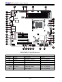
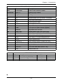
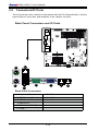
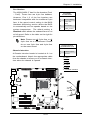
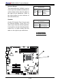
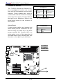
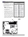
X8SIL/X8SIL-F Headers/Connectors
Number
Connector
Description
4,16
COM1/COM2
COM1/2 Serial connection headers
33,32,27,23,7
Fans 1~5
System/CPU fan headers
34
Floppy
Floppy Disk Drive connector
5
JAR
Alarm Reset
30
JD1
Speaker header (Pins 3/4: Internal, 1~4:External)
28
JF1
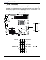
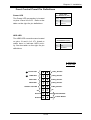
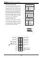
Front Panel Control header
18
JL1
Chassis Intrusion header
29
JLED
Power LED Indicator header
37
JPW1
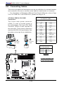
24-pin ATX main power connector (required)
36
JPW2
+12V 8-pin CPU power connector (required)
1
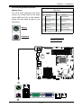
KB/Mouse
Keyboard/mouse connectors
8,9
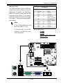
LAN1~LAN2,
Gigabit Ethernet (RJ45) ports (LAN1/LAN2)
22
I-SATA 0~5
Serial ATA ports (X8SIL has 4 Serial ATA Ports)
2
IPMI
IPMI LAN Port (X8SIL-F Only)
35
JPI2C
PWR supply (I2C) System Management Bus
31
SPKR1
Internal speaker/buzzer
24
T-SGPIO-0/1
Serial General Purpose IO headers (for SATA)
3,21
USB0/1, USB 2/3
Backplane USB 0/1, Front panel accessible USB 2/3
20
USB 4
Type A USB Connector
19
USB 10/11
Front Panel USB header (X8SIL-F Only)
6
VGA
Onboard Video Port
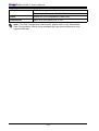
X8SIL/X8SIL-F LED Indicators
Number
LED
Description
Color/State
Status
26
LE4
Onboard Standby PWR LED
Green: Solid on
PWR On
15
LE7
IPMI Heartbeat LED
Yellow: Blinking
IPMI: Normal
1-5