1
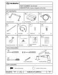
INSTALLATION
INSTRUCTIONS
REMOTE KEYLESS
ENTRY SYSTEM
FORESTER
P/N: H7110FS300
Kit Contents:
1
Keyless Entry Control Module w/Integral Bracket
2
Remote Control Transmitters
1
Installation Manual
Tools Required:
#1 Flat-tip Screwdriver
#2 Phillips Head Screwdriver (short)
1/4” Drive Ratchet
4-inch 1/4” Drive Extension
1/4” Swivel
10 mm Socket
This device complies with FCC rules part 15. Operation is
subject to the following two conditions: (1) this device may
not cause harmful interference and (2) this device must
accept any interference that may cause undesired operation.
1
99.11
UT27T-11
Printed in Japan
A. Pre-Installation Notes
1. Vehicle Preparation
a. Lower the driver’s side window to avoid inadvertently locking the keys in the vehicle during
installation.
b. Note and record station presets on radio for step #2 in section E. Finish the Installation.
c. Disconnect negative battery terminal to prevent accidental shorting of any power circuits.
2. System Preparation
Remove the keyless module and transmitters from the package and inspect for any physical damage.
B. Installation
1. Remove one plastic screw and two metal screws indicated by the arrows in Figure 1. Remove the lower dash
panel by pulling the upper side of the lower dash panel
toward you.
2. Disconnect four harnesses (two white housings, one
brown housing and one black housing) on the lower
dash panel. Then completely remove the lower dash
panel.
Figure 1
NOTE: To detach the black housing, insert a slotted
screwdriver as shown in Figure 2 and lift up
the black housing. The black housing can be
detached easily.
Figure 2
2
3. Remove two M6 nuts, indicated by arrow in Figure 3,
securing both the door lock timer module. Retain nuts
for installation of keyless entry module. Disconnect the
door lock timer harness from the module and discard the
module. Disconnect 6-pin to 16-pin extension harness
from the 16-pin (white housing) connector. Discard the
extension harness.
Figure 3
4. Insert the 16-pin (white housing) connector into the keyless entry module.
5. Install the keyless entry module to the location previously used by the door lock timer module and secure it
in place with two M6 nuts removed in Step 3. Refer to
Figure 4 which shows the installed keyless entry module.
Figure 4
NOTE:
The installed direction of the keyless entry module
should be as shown in Figure 5.
Figure 5
3
C. System Test
1. Reconnect the negative battery terminal.
2. Close all vehicle doors (with dome light switch set to “Doors”).
3. Depress the LOCK/ARM button on the remote and the following should be observed:
3.1 All vehicle doors will lock
3.2 The vehicle courtesy (dome) light will turn off
3.3 The horn will chirp once.
4. Depress the UNLOCK/DISARM button on the remote and the following should be observed:
4.1 The driver’s door will unlock
4.2 The vehicle courtesy (dome) light will turn on (for a maximum of 30 seconds unless a door
is opened and/or the ignition key is turned on)
4.3 The horn will chirp twice.
5. Depress the UNLOCK/DISARM button a second time and the remaining doors should unlock.
6. Depress and hold the LOCK/ARM button (panic mode) for more than 2 seconds and the following
should be observed:
6.1 The horn will sound (for a maximum of 30 seconds or until a button on the remote is
depressed).
7. Depress any button on the remote and the horn should stop sounding.
8. Depress the UNLOCK/DISARM button.
9. Simultaneously depress and hold the LOCK/ARM and UNLOCK/DISARM buttons for more than
2 seconds and the following should be observed:
8.1 The horn will chirp 2 times indicating that the audible verification has been turned off.
10. Depress the LOCK/ARM button on the remote and the following should be observed:
9.1 All vehicle doors will lock
9.2 The vehicle courtesy (dome) light will turn off
9.3 NO HORN SHOULD BE HEARD.
11. Depress the UNLOCK/DISARM button on the remote and the following should be observed:
10.1 The driver’s door will unlock
10.2 The vehicle courtesy (dome) light will turn on (for a maximum of 30 seconds unless a door
is opened and/or the ignition key is turned on)
10.3 NO HORN SHOULD BE HEARD.
12. Simultaneously depress and hold the LOCK/ARM and UNLOCK/DISARM buttons for more than
2 seconds and the following should be observed:
11.1 The horn will chirp 1 time indicating that the audible verification has been turned on.
13. Repeat steps 3 and 4 to ensure that audible mode is once again functioning.
14. Repeat steps 2 through 7 with the second remote transmitter.
D. Notes on System Operation
1. The panic mode will remain active for 30 seconds unless another button on the remote is activated
to cancel the mode.
2. If any secured opening (including rear hatch) is open at the time of depressing LOCK/ARM on the
remote transmitter, the horn will chirp 3 times indicating that all openings have not been properly
closed. Upon closing, all doors will lock automatically.
3. Audible “ON” “OFF” can not be toggled unless the driver’s door is unlocked.
4
E. Finish the Installation
1. Replace the lower dash panel below the steering column previously removed in section B.
2. Reset presets on radio as noted in step 1. b. in section A. Pre-Installation Notes.
Installation is now complete.
5