1
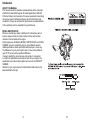
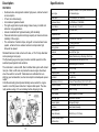
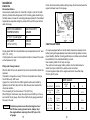
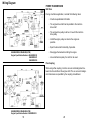
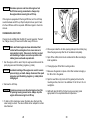
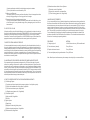
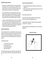
INSTRUCTIONS FOR USE
MODEL EH64
WELDER APPLICATION
CONTENTS
LIMITED ENGINE WARRANTY ..........................................................3
SAFETY PRECAUTIONS....................................................................6
INTRODUCTION .................................................................................9
DESCRIPTION .................................................................................. 11
SPECIFICATIONS.............................................................................12
INSTALLATION .................................................................................13
OPERATION......................................................................................21
PERIODIC MAINTENANCE ..............................................................27
ADJUSTMENTS ................................................................................33
TROUBLESHOOTING ......................................................................35
HOW TO SELECT A SERVICE DEALER..........................................53
WARNING
The engine exhaust from this product contains chemicals known to
the State of California to cause cancer, birth defects or other
reproductive harm.
2ZZ-90201-07
1
NOTICE
The FEDERAL EMISSION COMPONENT DEFECT WARRANTY and
CALIFORNIA EMISSION CONTROL WARRANTY stated in the beginning of this manual are only applicable to the engines sold and used in
the U.S.A.
To the engines exported to and used in the countries other than the
U.S.A., warranty service shall be performed by the distributor in each
country in accordance with the standard Robin engine warranty policy
as applicable.
2
3 Year Limited Engine Warranty
6.
(Special Term for Welder Application)
Engine tune-ups and normal maintenance service including, but not limited to, valve
adjustment, normal replacement of service items, fuel and lubricating oil, etc.
7.
Any engine which has been subject to negligence, misuse, accident, misapplication or over-speeding.
8.
Any engine that has been installed, repaired, or altered by anyone in a manner which
in Robin’s sole judgment adversely affects its performance or reliability.
9.
Any engine which has been fitted with or repaired with parts or components not
manufactured or approved by Robin which in Robin’s sole judgment adversely
affects its performance or reliability.
(Effective with engines purchased from Robin America, Wood Dale, IL, after November 15,
1993)
Robin America, Inc., a division of Fuji Heavy Industries, Ltd. (herein “Robin”), warrants that
each new engine sold by it will be free, under normal use and service, from defects in material
and workmanship for a period listed below from the date of sale to the original retail purchaser.
Robin’s obligation under this Limited Warranty shall be limited to the repair and replacement,
at Robin’s option, of any part or parts which upon examination is/are found, in Robin’s
judgment, to have been defective in material or workmanship. It shall be a condition of Robin’s
obligation under this Limited Warranty that Robin, directly or through one of its Distributors or
Service Centers authorized to service the particular engine involved, receive prompt notice of
any warranty claim and that the engine or the part or parts claimed to be defective be promptly
delivered, transportation prepaid, to such Distributor or Service Center for inspection and
repair. All repairs qualifying under this Limited Warranty must be performed by Robin or one
of its authorized Distributors or Service Centers.
WARRANTY PERIODS:
Robin V-Twin, Welder ApplicationLimited 3 years Warranty
(Applies to Original OEM installed engine)
The repair or replacement of any part or parts under this Limited Warranty shall not extend the
term of the engine warranty beyond the original term as set forth above.
LIMITATIONS AND EXCLUSIONS: This Limited Warranty shall not apply to:
1.
Bent or broken crankshaft or resultant damage caused by vibration related to a
bent or broken crankshaft. Also, damage caused by loose engine mounting bolts or
improper or imbalanced accessories or blades mounted to the crankshaft.
2.
Repairs required because of prolonged storage including damage caused by old or
contaminated fuel in the fuel tank, fuel lines or carburetor, sticky valves or corrosion
and rust of engine parts.
3.
Repair required due to overheating. (Most often caused by overloaded or clogged or
damaged or missing flywheel, fan, inlet air passages, cooling fins or air shrouds.)
4.
Dirt or grit related wear caused by improper air cleaner maintenance (most often
10.
Instances when normal use has exhausted the life of a component or an engine.
The customer is responsible for all transportation charges in connection with any warranty
work.
Robin reserves the right to modify, alter or improve any engines or parts without incurring any
obligation to modify or replace, any engine or parts previously sold without such modification,
alternation or improvement.
No person is authorized to give any other warranty or to assume any additional obligation on
Robin’s behalf unless made in writing and signed by an officer of Robin.
THIS WARRANTY, AND ROBIN’S OBLIGATION HERE
UNDER, ARE IN LIEU OF ANY OTHER WARRANTIES
OR OBLIGATIONS OF ANY KIND, EXPRESSED
OR IMPLIED, INCLUDING ANY WARRANTIES OF
MERCHANTABILITY OR FITNESS FOR A PARTICULAR
PURPOSE. THERE ARE NO WARRANTIES WHICH
EXTEND BEYOND THE DESCRIPTION ON THE
FACE HERE-OF. ROBIN SHALL IN NO EVENT BE
LIABLE FOR ANY CONSEQUENTIAL OR INCIDENTAL
DAMAGES.
resulting in worn piston, piston rings, cylinders, valves, valve guides, carburetor or
other internal components).
5.
Broken or scored parts caused by low oil level, dirty or improper grade of oil.
3
4
WARNING :
The engine exhaust from this product contains
chemicals known to the State of California to
cause cancer, birth defects or other reproductive
harm.
NOTICE
FEDERAL EMISSION COMPONENT DEFECT WARRANTY and CALIFORNIA
EMISSION CONTROL WARRANTY are applicable to only those engines
complied with EPA (Environmental Protection Agency) and CARB (California
Air Resources Board) emission regulations in the U.S.A.
NOTICE
For the engines exported to and used in the countries other than the U.S.A.,
warranty service shall be performed by the distributor in each country in accordance with the standard Robin engine warranty policy as applicable.
Safety Precautions
Before operating the engine, read this manual and become
familiar with it and the equipment. Safe and efficient operation
can be achieved only if the equipment is properly operated and
maintained.
The following symbols, found throughout this manual, alert you to
potentially dangerous conditions to the operator, service personnel, or
the equipment.
! DANGER
This symbol warns of immediate hazards which will
result in severe personal injury or death.
! WARNING
This symbol refers to a hazard or unsafe practice
which can result in severe personal injury or death.
! CAUTION This symbol refers to a hazard or unsafe practice
which can result in personal injury or product or property
damage.
AIR INDEX
To show compliance with California emission regulations, a hangtag has been
provided displaying the Air Index level and durability period of this engine.
The Air Index level defines how clean an engine’s exhaust is over a period of
time. A bar graph scaled from “0” (most clean) to “10” (least clean) is used to
show an engine’s Air Index level. A lower Air Index level represents cleaner
exhaust from an engine.
Fuels, electrical equipment, batteries, exhaust gases and moving parts
present potential hazards that can result in severe personal injury.
Take care in following these recommended procedures. All local, state
and federal codes should be consulted and complied with.
! WARNING
The period of time (in hours) that the Air Index level is measured is known as
the durability period. Depending on the size of the engine, a selection of time
periods can be used to measure the Air Index level (see below).
Descriptive Term
This engine is not designed or intended for use in
any type of aircraft. Use of this engine in aircraft can result
in engine failure and cause severe personal injury or
death.
Applicable to Emissions Durability Period
Moderate
-
50 hours (engine from 0 to 65 cc)
125 hours (engine greater than 65 cc)
Intermediate
-
125 hours (engine from 0 to 65 cc)
250 hours (engine greater than 65 cc)
Extended
-
300 hours (engine from 0 to 65 cc)
500 hours (engine greater than 65 cc)
Notice : This hangtag must remain on this engine or piece of equipment, and
only be removed by the ultimate purchaser before operation.
5
GENERAL
• Provide appropriate fire extinguishers and install them in convenient
locations. Use an extinguisher rated ABC by NFPA.
• Make sure that all fasteners on the engine are secure and
accurately torqued. Keep guards in position over fans, driving belts,
etc.
• If it is necessary to make adjustments while the engine is
running, use extreme caution when close to hot exhausts,
6
moving parts, etc.
• Used engine oils have been identified by some state and
federal agencies as causing cancer or reproductive toxicity. When
checking or changing engine oil, take care not to ingest, breathe
the fumes, or contact used oil.
• Do not work on this equipment when mentally or physically
fatigued, or after consuming any alcohol or drug that makes
the operation of equipment unsafe.
BATTERIES
• Before starting work on the engine, disconnect batteries to prevent
inadvertent starting of the engine. Disconnect negative (-) cable first.
• DO NOT SMOKE while servicing batteries. Lead acid batteries give
off a highly explosive hydrogen gas which can be ignited by flame,
electrical arcing or by smoking.
• Verify battery polarity before connecting battery cables. Connect
negative (-) cable last.
PROTECT AGAINST MOVING PARTS
• Do not wear loose clothing in the vicinity of moving parts, such as
PTO shafts, flywheels, blowers, couplings, fans, belts, etc.
• Keep your hands away from moving parts
FUEL SYSTEMS
• DO NOT fill fuel tank while engine is running
• DO NOT smoke or use an open flame in the vicinity of the engine or
fuel tank. Internal combustion engine fuels are highly flammable.
• Fuel line must be made of steel tubing which adequately secured,
and free from leaks. Tubing which connects to the carburetor should
be factory approved flexible line. Do not use copper tubing as the
flexible lines as copper will harden and become brittle enough to
break.
• Be sure all fuel supplies have a positive shutoff valve.
• Benzene and lead, found in some gasoline, have been identified by
some state and federal agencies as causing cancer or reproductive
toxicity. When checking, draining, or adding gasoline take care not
to ingest, breathe fumes, or contact the gasoline.
7
EXHAUST SYSTEM
• Exhaust products of any internal combustion engine are toxic and
can cause injury, or death it inhaled. When operating the engine in a
confined area, make sure the ventilation system is operating
properly.
• DO NOT use exhaust gases to heat a compartment.
• Make sure that your exhaust system is free of leaks. Make sure that
exhaust manifolds are secure and are not warped by bolts unevenly
torqued.
EXHAUST GAS IS DEADLY!
Exhaust gases contain carbon monoxide, a poisonous gas that can
cause unconsciousness and death. It is an odorless and colorless gas
formed during combustion of hydrocarbon fuels. Symptoms of carbon
monoxide poisoning are:
• Dizziness
• Vomiting
• Headache
• Muscular Twitching
• Throbbing in Temples
• Weakness and Sleepiness
If you experience any of these symptoms, get out into fresh air immediately, shut down the unit and do not use it until it has been inspected.
The best protection against carbon monoxide inhalation is proper
installation and regular, frequent inspections of the complete exhaust
system. If you notice a change in the sound or appearance of exhaust
system, shut the unit down immediately and have it inspected and
repaired at once by a competent mechanic.
KEEP THE UNIT AND SURROUNDING AREA CLEAN
• Make sure that oily rags are not left on or near the engine.
• Remove all unnecessary grease and oil from the unit. Accumulated
grease and oil can cause overheating and subsequent engine
damage and present a potential fire hazard.
8
Introduction
ABOUT THIS MANUAL
This manual covers the operation and maintenance of the horizontalshaft Robin Subaru EH64 engines for welder applications (OHV220
Performer Series). Each operator of the power equipment should study
this engine manual carefully and observe all of its instructions and
precautions. Proper use and periodic maintenance are responsibilities
of the operator(s) and are essential for top performance.
MODEL IDENTIFICATION
Whenever contacting a dealer or distributor for information, parts or
service, always provide the model number and the serial number
marked on the nameplate of the engine.
Robin engines are identified by MODEL, SPECIFICATION, and CODE
NUMBER. For each model there may be many different versions
called specifications. Each specification will be unique in some way.
The difference may only be the paint color or it may have a different
type of PTO or some other significant difference.
In order to identify the correct service part number, it is important
to confirm the specification and code numbers for your engine. The
specification and code number together are know as the PRODUCT
NUMBER.
All Robin 4 cycle engine have a Product Number label similar to the
label illustrated to the right.
9
10
Description
Specifications
FEATURES
• Overhead valve arrangement enables high power, and low fuel and
oil consumption
• V-Twin, four stroke design
• Air-cooled and gasoline fueled
• The light weight and compact design makes it easy to install and
utilize for many applications.
• A steel crankshaft and high-load bearing offer durability
• Pressure lubrication system and large capacity air cleaner enhance
reliability of the engine.
• The combustion chamber shape, along with a tuned exhaust valve
system, enhance the low exhaust emission and provides high
torque at low speed.
Standard features include a fuel cut-of valve, a 12V-15 amp alternator
and a pulse-type fuel pump.
The flywheel-type governor gear provides constant operation at the
selected speed against load variations.
The carburetor is a down draft, float controlled fuel system with a fixed
main jet. A fuel cut-off valve is provided to secure engine shut-down
when the switch is turned off. Carburetors are calibrated for sure
starting, good acceleration, low fuel consumption and adequate power
output.
A throttle solenoid (optional) automatically senses when the engine
needs to run at full power and when it requires idle speed. The solenoid operates using a 15 second delay before dropping to idle.
11
Engine Type
Air-Cooled, 4-Stroke, V-Twin Cylinder, Horizontal Shaft,
OHV Gasoline Engine
Rated Output
20.5 HP/3600 rpm (153. kW/3600)
Continuous Output
16.0 HP/3600 rpm (11.9kW/3600)
Bore X Stroke
80 mm x 65 mm (3.15” x 2.56”)
Displacement
653cc (39.90 cu in)
Compression Ratio
8.3:1
Maximum Output
15.3 kW/20.5 HP / 3600 rpm
Maximum Torque
32.7 ft/lbs @ 2200 rpm
Starting System
Electric Start
Carburetor
Down draft, Float Type
Fuel
Unleaded Gasoline using a Diaphragm Pulse Pump
Lubrication
Full Pressure with full Flow Spin-On Filter
Oil Type
Automobile Engine Oil; Class SE
Oil Capicity
1550 cc (1.64qt)
Charging System
12 volt 15 amp
Dry Weight
44 kg (96.9 lbs)
Dimensions (L x W x H)
317mm x 477mm x 475mm (12.5” x 19.0” x 19.0”)
Direction of Rotation
CCW as Viewed from the PTO shaft side
Cooling System
Forced Air Cooling
Ignition System
Flywheel Magneto (Solid State)
Spark Plug Type
NGK-BP6ES or BRP6ES
Governor System
Centrifugal Fly Weight
Air Cleaner
Double Element Assembly
Valve Clearance
(Intake & Exhaust)
0.003-0.005 in (0.07-0.10mm)
Emission Durability Period
(California Only)
500 hours
Installation
LOCATING
Locate the engine at least 1 meter (3.0 ft) away from buildings or other
structures. Provide proper exhaust routing. Refer to EXHAUST SYSTEM below. Do not use the engine near flammables or other hazardous materials such as trash, rags, lubricants, or explosives.
When determining the mounting location, make sure of the following:
• Gas and oil can easily be checked and supplied
• Oil can be changed.
• The air cleaner can be serviced
• Spark plugs can be checked.
Carefully examine the engines position, the method of connecting it to
a machine, and the foundation and support structure.
Locate the engine in a safe area on a stable level surface free of small
rock, loose gravel, etc.
! CAUTION
carburetor.
If the tank is mounted above the carburetor, a fuel shut-off valve must
be connected between the fuel tank and the fuel pump.
Note: To prevent fuel from flooding the carburetor, the fuel valve
must be closed when the engine is not running.
Properly install fuel lines to the carburetor bycompletely inserting the
hose onto the fitting and then secure it with a hose clamp.
! WARNING Gaseous fuels are flammable and explosive and
can cause severe personal injury or death.
Do not smoke if you smell gas or are near fuel
tanks or fuel-buring equipment or are in an area
sharing ventilation with such equipment. Keep
flames, sparks, pilot lights, electrical switches,
arc-producing equipment and all other sources
of ignition well away. Keep a type ABC fire
extinguisher handy.
Operating the engine on an incline may cause
seizure due to improper lubrication; even at
maximum oil level.
EXHAUST SYSTEM
EXHAUST GAS IS DEADLY! Engine-powered equipment must never
be operated inside buildings or other enclosed spaces.
If a long exhaust pipe is used, the internal resistance results in loss
of engine power. The exhaust pipe ID must increase in proportion to
exhaust pipe length. For example, if the exhaust pipe is:
less than 3.0 m (9.8 ft.) long - pipe ID = 30mm (1-3/16in)
less than 5.0 m (16.4 ft)long - pipe ID = 33mm (1.3in)
It is the responsibility of the equipment operator(s) to check for
exhaust leaks on a daily basis and to have all leaks repaired before
continuing to operate the equipment.
FUEL
Fuel Tank
The fuel tank system must be provided by the OEM. A fuel
shut-off valve must connected between the fuel line and the fuel pump.
The fuel tank may be mounted up to 0.66 meters (2.0ft) below the
13
Do not refill the fuel tank while the engine is running. Do not overfill the
tank.
Wipe away any spilled fuel and wait until it has dried before starting
the engine.
Fuel recommendations
Use clean, fresh unleaded gasoline having a minimum octane rating (Anti-Knock Index) of 87. This engine is certified to operate on
unleaded gasoline.
During some periods of the year only mandated “oxygenated” gasolines may be available. These are acceptable for use, but not preferable. Do not use gasoline or gasoline additives (de-icers) containing
methanol because methanol can be corrosive to fuel system components.
! CAUTION
Do not use gasoline or gasoline additives
containing methanol because methanol can be
corrosive to fuel system components.
14
Installation
ENGINE OIL
Recommendations
Use premium quality motor oil, Class SE or higher. Look for the SAE
(Society of Automotive Engineers) or API viscosity grade. Referring to
the table below, choose the viscosity grade appropriate for the ambient
temperatures expected during the period of time until the next scheduled oil change.
EXPECTED AMBIENT
TEMPERATURES
SAE VISCOSITY
GRADE
32°F (0° C) and higher
30
0°F to 80°F
(-18°C to 27°C)
10W-30
10W-40
Single-grade SAE 30 oil is preferable when temperatures are 50° and
90°F (10° - 32°C).
If multi-grade oil is used, oil consumption tends to increase if the ambient temperature is high.
Filling and Change Interval
After the first 20 hours of operation the initial oil and oil filter should be
replaced.
Thereafter, change the oil every 100 hours of operation and change
the oil filter every 200 hours.
Apply a thin coat of oil to the oil filter gasket surface and install by
tightening the oil filter about 3/4 turn after the seal has reached the
crankcase surface.
The oil capacity of the crankcase is 1.55L (53 fl.oz.).
When filling the crankcase, keep the engine level and fill up to the upper mark of the oil gauge. Check the oil with the oil gauge pushed all
the way in its seat.
! WARNING Crankcase pressure can blow hot engine oil out
the fill tube causing severe burns. Always stop
the engine before removing the oil fill cap or the
oil gauge.
15
Check the oil level daily, before starting. Keep the oil level between the
upper and lower level on the gauge.
STARTING BATTERIES
An engine equipped with an electric starter requires a properly sized
battery along with appropriately sized interconnecting cables to insure
proper starting. Neither cranking performance or starter service life will
be satisfactory if an undersized battery is used.
Use a battery rated 12V-30 amp or larger.
The customer must supply battery cables. Use the table below to
select the proper cable for the positive side connection.
Connect a ground strap to the negative terminal. Use a flat strap
25.0mm (0.25”) wide.
WIRE GAUGE
CABLE LENGTH
CABLE DIA.
AWG (BS)
BWG
SAE
JIS
Less than 1.5m
(4.5ft)
7.3mm
(5/16 in.)
1
6
AV15
1.5 - 2.5m
(4.5 - 7.6ft)
8.5 mm
(3/8 in.)
0
4
AV20
2.5 - 4.0m
(7.6 - 12.2ft)
108 mm
(7/16in.)
3/0
2
AV30
16
Installation
WIRING
BATTERY CABLES
The engine is equipped with a wiring harness that connects with the
accessory.
1. Connect the positive (+) battery cable between the starter solenoid
and the battery.
2. Connect the ground strap between the negative (-) battery terminal
and a clean, bare metal grounding location on the engine.
3. Connect wires from starter key switch to starter solenoid and
ground.
WIRE GAUGE
CABLE
LENGTH
CABLE DIA.
AWG (BS)
BWG
SAE
JIS
Less than 1.5 m
(4.5ft)
1.5mm
(1/16in)
14
16
AV1.25
1.5-3.0m
(4.5-9.8ft)
1.9mm
(5/64in)
12
14
AV2
3.0-5.0m
(9.8-16.4ft)
2.4mm
(1/10in)
10
13
AV3
STARTER SWITCH
A customer supplied starter switch or key switch is recommended for the starter motor. See table below for switch cable
recommendations.
17
18
Wiring Diagram
POWER TRANSMISSION
Belt Drive
If using a belt drive application, consider the following notes:
• V-belts are preferable to flat belts
• The engine drive shaft must be parallel to the machine
drive shaft
• The engine drive pulley must be in line with the machine
drive pulley
• Install the engine pulley as close to the engine as
possible
• Span the drive belt horizontally, if possible.
ENGINE WIRING DIAGRAM (6 PIN)
Engine Specification Numbers: EH650DB2332
EH650DB2341
EH650DB2390
• Disengage the load when starting the engine.
• Use a belt tension pulley if a clutch is not used.
Flex Coupling
When using a flex coupling, minimize run-out and misalignment between the drive shaft and the engine shaft. The run-out and misalignment tolerances are specified by the coupling manufacturer.
ENGINE WIRING DIAGRAM (4 PIN)
Engine Specification Number: EH650DB2332
19
20
Operation
any indications of fuel leakage. Do not operate engine until
all leaks are repaired.
! WARNING EXHAUST GAS IS DEADLY!
Exhaust gases contain carbon monoxide, an odorless and colorless gas. Carbon monoxide is poisonous and can cause unconsciousness and death. Symptoms of carbon monoxide poisoning
include:
• Dizziness
• Throbbing in Temples
• Nausea
• Muscular Twitching
• Headache
• Vomiting
• Weakness and Sleepiness
• Inability to Think Coherently
IF YOU OR ANYONE ELSE EXPERIENCE ANY OF THESE SYMPTOMS, GET INTO THE FRESH AIR IMMEDIATELY. If symptoms
persist, seek medical attention. Shut down the engine and do not
operate it until it has been inspected and repaired.
Make certain the exhaust system is properly installed. Inspect
it every time the engine is started and after every eight hours of
continuous operation.
PRE-START CHECKS
Before the first start of the day and after every eight hours of operation
perform the maintenance procedures in DAILY
(8 HOUR) MAINTENANCE in the Maintenance Section.
Keep a log of maintenance and the running hours. Perform any maintenance that may be due. If the equipment has been in storage, return
the engine to service as instructed under
RETURNING THE ENGINE TO SERVICE in this section.
1.
Inspect exhaust system for loose joints, rusty, worn or damaged
areas. Do not operate engine until all leaks are repaired.
2.
Check the fuel level and refill if necessary. Open the fuel shut-off
valve (if equipped).
3.
Make sure fuel hoses and connections are tight. Check for
21
4.
Check and tighten any loose bolts or nuts.
5.
Check the oil and refill, if necessary. Do not overfill.
! CAUTION Starting the engine without oil will cause severe
engine damage.
Always keep the engine oil level between the
Full and Add marks on the dipstick.
6.
Wear snug fitting clothes when operating the engine. Loose
articles of clothing could get caught in the engine or drive train.
! WARNING Moving parts can cause severe personal injury or
death. Hot exhaust parts can cause severe burns.
Stay clear of hot or moving parts. Make sure all
protective shields and guards are secure in place
before starting the equipment.
STARTING
1. Move the choke lever to the full-choke position. On equipment
with a solenoid operated choke, push the switch to its choke
position. In warm weather, however, or when the engine is warm,
try starting without the choke or in the half-way position.
2. Turn the ignition switch to START and hold it there until the engine
starts. Do not crank for more than 5 seconds at a time.
If the engine fails to start, set the switch to RUN and wait 10
seconds before the next attempt. See Troubleshooting if the
engine does not start after several tries. Never turn the switch to
START while the engine is running.
22
3. After the engine starts, slowly push the choke to the fullopen position. Pull it back, if necessary, to keep the engine
running smoothly until the engine is at operating temperature
In colder weather, the engine will take longer to begin
running smoothly with the choke open.
Do not operate the equipment until the choke is fully open.
OPERATING IN DUSTY CONDITIONS
1.
Keep the engine cooling fins and flywheel air inlet screen clean.
2.
Perform air cleaner maintenance more often than normal-as
required.
3.
Change the engine oil and oil filter more often than normal.
STOPPING
HOT AND COLD WEATHER PRECAUTIONS
To stop the engine turn the switch to the STOP position.
Hot Weather
ENGINE BREAK-IN
Pay particular attention to the following items when operating the
engine in temperatures above 100°F (38°C):
For top engine performance, new or rebuilt engines require a breakin period to obtain the ideal fitting of internal moving metal parts. To
break-in the engine:
1. Keep the flywheel air inlet screen and cylinder cooling fins clean.
Make sure that nothing obstructs air flow to and from the engine
1. Run the engine at 2500 rpm, without a load, for 10 minutes.
2. Run the engine at 3,000 rpm for 10 minutes.
2. Check the oil level more frequently.
3. Change the oil and oil filter more often than normal.
3. Run the engine at 3,600 rpm for 10 minutes.
4. Make sure the engine oil viscosity is appropriate for the ambient
temperatures and change the oil if necessary.
4. Run the engine with a load of 8HP at 3,600 rpm for 30 minutes.
Cold Weather
5. Run the engine with a load of 16HP at 3,600 rpm for 30 minutes.
Pay particular attention to the following items when operating the
engine in temperatures blow freezing:
Frequently check for oil leaks during break-in.
After the first 20 hours of normal operation, change the oil and oil filter.
Refer to
Maintenance for procedures.
23
1. Make sure the engine oil viscosity is appropriate for the ambient
temperatures and change the oil if necessary. If the temperature
drops before you have the chance to change the oil, warn the
engine by moving the equipment into a heated space before
attempting to start the engine or change the oil.
24
! WARNING EXHAUST GAS IS DEADLY!
Never operate engine-powered equipment
indoors without a proper exhaust system, ample fresh
air ventilation and an operable carbon monoxide
detector.
2. Use fresh gasoline and fill the fuel tank after each day’s use to
reduce problems with moisture condensation if this is a gasoline
engine.
3. Keep the battery in a well-charged condition.
4. After each use push the equipment throttle knob or lever to the
middle of its speed range. Then, if ice forms on the linkage during
storage it will be easier to start the engine.
6 Perform air cleaner maintenance as instructed in Periodic
Maintenance.
7 Plug the exhaust outlet to prevent moisture, dirt, bugs, ect. from
entering.
! WARNING Battery gas is explosive. Wear safety glasses
and do not smoke while servicing batteries. Lead acid
batteries give off a highly explosive hydrogen gas
which can be ignited by flame, electrical arcing or
smoking.
8 Disconnect the battery (negative (-) cable first) and follow the
battery or equipment manufacturer’s storage instructions.
9 Cover the engine with a plastic sheet or canvas and store in a dry
place.
OUT-OF-SERVICE PROTECTION
RETURNING THE ENGINE TO SERVICE
Protect an engine that will be out of service for more than 30 days as
follows:
1 Remove the cover and all protective wrapping and the plug from the
exhaust outlet.
1 Run the engine until it reaches normal operating temperature then,
shut-off the fuel supply and let the engine run until it stops.
2 Check the tag on the oil base. Change the oil if the viscosity is not
appropriate for the expected ambient temperatures.
2 If the equipment will not be operated for more than 30days, add a
fuel preservative (ie. Sta-Bil) to the equipment fuel tank. Follow the
instructions on the container label. Unless a preservative is added,
gasoline will deteriorate causing fuel system corrosion, gum
formation and varnish-like deposits which can lead to hard starting
and rough operation.
3 Check the fuel filter and fuel lines to make sure they are secure and
have no cracks.
3 Drain oil from the engine while it is still warm. Refill with fresh oil
and attach a tag stating the viscosity of the oil used.
4 To prevent rust in the cylinder bore, remove the spark plug and pour
30mL (2 tbsp. or 1oz.) of SAE 30 oil in the opening. Turn the
crankshaft several times by hand and reinstall the spark plug.
4 Check that the choke, throttle and governor linkages move freely.
5 If so equipped, clean and check the battery according to the battery
or equipment manufacturer’s instructions and connect the battery
cables (positive (+) cable first).
6 Start the engine. The initial startup may be slow and there may be
smoke and rough operation for a few minutes until the oil in
the cylinder burns off. If the engine does not start, clean or replace
the spark plug as it may have been fouled by the oil added to the
cylinder when the equipment was stored.
5 Clean the outside of the engine with an oiled cloth.
25
26
Periodic Maintenance
Periodic Maintenance
MAINTENANCE, REPLACEMENT, OR REPAIR OF THE EMISSION
CONTROL DEVICES AND SYSTEMS MAY BE PERFORMED BY
NON-ROAD ENGINE REPAIR ESTABLISHMENTS OR
INDIVIDUALS.
Periodic maintenance is essential for top engine performance. See the
Table below as a guide for normal periodic maintenance. Under hot or
dusty operating conditions some maintenance operations should be
performed more frequently, as indicated by footnotes in the table.
FREQUENCY
MAINTENANCE OPERATION
Daily or
Every 8
Hours
Clean Dust and Debris
from Engine
X
Check fuel leakage from
fuel system. Retighten
fasteners or replace parts
if needed.
X1
Inspect for Loose Hardware
and Retighten
X
Check Oil Level and Add to
Full Level
X
Every
50
Hours
Every
100
Hours
Every
200
Hours
Every
500
Hours
Every
1,000
Hours
Keep a log of maintenance performed and the run time hours. Keeping
a record of procedures will help you keep scheduled maintenance and
provide a basis for supporting warranty claims
Maintenance, replacement or repair of emission control devices and
systems may be performed by any engine repair establishment or
individual. However, warranty work must be done completed by an
authorized Robin Subaru dealer or distributor.
DAILY (8 HOUR) MAINTENANCE
The operator should check the following before the first start of the day
and after every eight hours of operation:
1 Inspect fuel lines and fittings for leaks. Repair leaks immediately.
2 Look and listen for exhaust system leaks while the engine is
running. Look for cracks and severe rusting in the muffler and
tailpipe. Have all leaks repaired before continuing to operate the
equipment.
X2,4
Change Engine Oil
Check Battery Fluid Level
X5
Clean Spark Plugs
X
Clean Outer Element of
Air Cleaner
X
! WARNING Hot exhaust parts can cause severe burns.
Allow the engine time to cool before servicing
the exhaust system.
Clean Fuel Strainer
X
Replace Air Cleaner Assembly
X
Inspect, Clean and Re-Gap
Spark Plugs
3 Check the engine for dirt and debris and clean the flywheel air inlet
screen and cylinder cooling fins as necessary.
X
! CAUTION A clogged flywheel air inlet screen or dirty cooling
X3,4
Change Engine Oil Filter
Clean Carburetor
X
Clean Cylinder Head
X
Adjust Engine Valve Clearance
X6
Replace Spark Plugs
X
Replace Fuel Lines and Filter
fins can cause overheating and engine damage. Keep
the cooling fins and air inlet screen clean.
X
1. Check for oil, fuel and exhaust leaks, loose parts and unusual noises and vibrations.
2. Change oil and filter after the first 20 hours of operation as a part of engine break-in.
3. Perform more often when operating in dusty conditions.
4. Perform more often when operating in hot conditions.
5. See instructions for battery care provided by the equipment or battery manufacturer.
6. Must be performed by a qualified mechanic (equipment or Robin dealer).
27
4 Check the engine oil level The equipment must be parked on a level
surface ad the engine stopped. To get an accurate reading, wait a
minute or so to allow the oil to settle in the crankcase if the engine
has been running.
28
! WARNING Crankcase pressure can blow hot engine oil out
the fill tube causing severe burns. Always stop
the engine before removing the oil fill cap.
If the engine is equipped with the long oil fill tube, turn the oil fill cap
counterclockwise and lift it up. Wipe the dip stick clean, push it back
into the oil fill tube until the cap seats. Withdraw it again to check the
oil level.
CHANGING OIL AND FILTER
Change the oil and filter after the first 20 hours of operation. Thereafter, change oil every 50 hours and the filter every 200 hours.
! WARNING State and federal agencies have determined that
contact with used engine oil can cause cancer or
reproductive toxicity. Take care to limit skin contact
and breathing of vapors as much as possible. Use
rubber gloves and wash exposed skin.
1 Run the engine until it is warm. Stop the engine and disconnect the
spark plug wires and the battery (negative (-) cable).
4 Place a pan under the oil drain opening and open the oil drain plug.
Close the plug securely after the oil has drained completely.
! WARNING Accidental starting of the engine can result in severe
7 Make sure the gasket is in place on the filter canister and apply a
thin film of oil to the gasket.
personal injury or death. Always disconnect the spark
plug wires and the battery (negative (-) cable) before
changing oil.
2 Remove the oil fill cap.
! WARNING Crankcase pressure can blow hot engine oil out the
fill opening causing severe burns. Always stop the
engine before removing the oil fill cap.
5 Spin off the oil filter, drain the oil and discard the filter according to
local regulations.
6 Thoroughly wipe off the filter mounting surface.
8 Spin the new filter on by hand until the gasket just touches the
mounting surface, then turn it an additional 1/2 to 3/4 turn. Do not
overtighten.
9 Refill with class SE (API) of higher having a viscosity grade
appropriate for the expected ambient temperature.
3 To drain oil from crankcase, loosen the drain valve then twist the
outer casing to unlock. The valve is fitted with an adapter for a drain
tube if desired.
29
30
10 DO NOT FILL TO A LEVEL ABOVE THE FULL MARK ON THE
DIPSTICK. Drain the excess oil if too much has been added.
Foam Filter
Remove and wash the urethane foam in water and detergent.
Squeeze the foam wrapper dry like a sponge. Rinse with clean water
and allow it to dry. Coat the wrapper evenly with 14 mL (one tbsp.) of
SAE 30 engine oil. Knead the oil into the wrapper and squeeze out the
excess oil.
Note: Failure to adequately wring out excess oil from the wrapper
may cause a drop in engine power due to restriction of inlet air.
Install the foam wrapper over the paper air cleaner element by stretching it over the inner cover. Completely cover all exposed paper pleats.
Replace the air cleaner assembly when it becomes torn or stretched.
Air Cleaner Element Replacement
! CAUTION
Too much oil can cause high oil consumption, high
operating temperatures and oil foaming. Too little oil
can cause severe engine damage. Keep the oil level
between the Full and Add marks on the dipstick.
11 Reconnect the spark plug wires and battery.
12 Start the engine and run it for a short time while checking for oil
leaks around the drain plug and oil filter. Do not overtighten: tighten
only as necessary to eliminate leaks.
To keep anything from entering the carburetor and engine while the
air cleaner element is off, pull the choke knob to the full-choke position to close the choke plate in the carburetor. Remove the outer cover
and wipe away loose dust and debris from the air cleaner assembly.
Remove the air cleaner assembly. Wipe off dust and debris from the air
cleaner base. Use forced air to blow off dust and debris from the paper
element.
Reinstall the paper element on the engine. Replace the foam wrapper
and outer cover. Secure with the wing nut.
Used oil is harmful to the environment. Pour the used oil into a sealed
container and deliver it to the nearest recycling center.
AIR CLEANER MAINTENANCE
Refer to the Maintenance Table for the air cleaner assembly.
Outer Cover
To remove the air cleaner cover, rotate the wing nut counterclockwise
and remove.
31
Element Set
P/N 263-32610-A1
32
SPARK PLUG MAINTENANCE AND REPLACEMENT
To adjust the speed control solenoid:
Refer to the Specifications for spark plug type and gap specifications.
Check and clean spark plugs every 200 hours. Replace plugs every
500 hours.
1 Run the engine with no load until the engine control times out
(about 15 seconds) and energizes the solenoid.
To prevent cross threading the spark plug, always thread it in by hand
until it seats. If the spark plug is being reused, turn it with a wrench
and additional 1/4 turn. If the spark plug is new, turn it an additional 3/8
to 1/2 turn. If you have a torque wrench, tighten a new spark plug to
11.8-14.7 N-m (120-150 Kg/cm) (8.7-10.9 ft/lb).
CHECKING BATTERIES
2 Adjust engine to 2200 RPM by loosening the two slotted screws
retaining the solenoid.
3 Slide solenoid forward to increase the speed, or backwards to
decrease the speed.
4 Retighten the two screws.
Every 50 hours or once a month check the fluid level of the battery.
Refill with distilled water if levels are low.
Following reassembly of either the carburetor or intake manifold, realign the governor arm on the governor shaft BEFORE making speed
adjustments to compensate for the slightly different alignment of parts.
! WARNING Battery gas is explosive. Wear safety glasses and do
Governor and Speed Control Assembly
not smoke while servicing batteries. Lead acid
batteries give off a highly explosive hydrogen gas
which can be ignited by flame, electrical arcing or
smoking.
1
2
! WARNING If the battery is to be replaced, disconnect the
3
negative cable first, and reconnect it last.
6
4
Adjustments
5
7
CARBURETOR ADJUSTMENTS
These engines have precision-manufactured carburetors which are not
adjustable.
Engine Speed Solenoid (Optional)
Normally, the engine speed does not require any adjustment. These
instructions are for the equipment manufacturer in setting up and
adjusting the equipment.
1
2
3
4
5
6
7
Speed Control Solenoid Adjust Screw (2) (Optional)
Governor Adjust Screws
Governor Lever
Speed Control High Stop Adjust Screw
Manual Throttle Control Link
Low Idle Adjust Screw
Choke Control Linkage
The speed control solenoid monitors the rate of the load and automatically adjusts the engine to the appropriate idle speed.
33
34
Speed Control Adjustments
Engine speed adjustment must be attempted only by a qualified mechanic and the adjustments must be made using an accurate tachometer. It is recommended that low-idle speed be adjusted between 1800
to 2200 RPM and high idle speed 3700 to 3800 RPM. Check in your
welder manufacture’s manual for exact speed settings.
Engine Starting
Engine cranks but
fails to start
Fuel Supply. Check fuel supply and shut-off valve. Check fuel filter
and clean if dirty. Check fuel filter: clean or replace if dirty. Check
fuel line connections into carburetor for air leaks.
Fuel. Gasoline may have water mixed in or the gasoline grade is
not correct.
Troubleshooting
The table below provides basic troubleshooting guidance. If you fail
to resolve the problem after taking the corrective actions suggested,
contact the equipment manufacturer or a Robin Subaru dealer.
Carburetor problems. Flooding carburetor, the float may be bad
or stuck. Varnish build up deposits in the carburetor, the carburetor
will have to be disassembled.
Governor and throttle linkage. Check linkage connections. Check
tension in springs. Check governor, throttle and speed adjustments
.
The fuel cut-off solenoid is faulty. Check for lose or damaged
wires and connectors. Check voltage levels at the connector to the
solenoid. Replace harness or solenoid.
Check air cleaner and service if dirty.
! WARNING Many troubleshooting procedures present hazards
that can result in severe personal injury. Only
qualified service personnel with knowledge of fuels,
electricity, and machinery hazards should perform
service procedures.
Review the safety precautions on the inside cover
page.
! WARNING Hot engine parts can cause severe burns. Always
Engine Starting
Electric starter
does not operate
allow the engine time to cool before performing any
maintenance or service.
Problem
Probable Cause and Remedy
Engine Starting
Engine cranks
slowly or not at all
Poor battery connections: Clean and tighten the positive (+) and
negative (-) connections at battery and engine.
Back pressure: There is excessive back pressure due to a
plugged or bent exhaust pipe.
No continuity between the key switch and the starter. Replace
wires.
Low battery. Change or recharge battery.
Starter solenoid is bad. Check voltages, clean repair, or replace.
Starter motor is bad. Check brushes and wiring, repair or replace.
Engine seizure. The crankshaft has seized or the piston and cylinder have seized. Check crankshaft bearings and bearing surface. 1
Electric starter is faulty: Check starter brushes and bearings.
There is a load on the engine: Remove load and retry.
Key or start switch. Check wiring connections and switch.
No continuity between the battery and starter. Replace cable.
Battery is not fully charged: Recharge the battery.
Improper engine oil: Change oil having the proper viscosity for
the ambient temperature.
Damaged spark plug(s). Check the spark plug gap. Check for
a bad insulator on plug and replace if damaged. Clean carbon
deposit from electrode. Id wet, dry electrode.
Engine Starting
Electric starter
operates but
engine does not
start
Low fuel.
Poor wiring connection or no continuity of ignition system.
Check wiring connections and ignition coils for a short.
Electric starter is bad. Slow cranking RPM is caused by low voltage at starter or worn brushes or bearings. Repair or replace.
Engine Overheats
Air flow is obstructed at inlet or cylinder baffle. Clean out
debris in baffle.
Improper engine oil. Replace oil.
Lean air/fuel mixture. Check for plugged passages in carburetor.
Excessive back pressure on exhaust. Check muffler and spark
arrester.
Engine is overloaded. Change to rated load.
Engine Idles
Rough
Low idle speed. Adjust idle on carburetor.
Air is mixing at air intake connection. Check, tighten or replace
gasket.1
There is blow-by on the head gasket. Replace the gasket. 1
Improper valve clearance. Adjust clearance. 1
Excessive clearance between valve stem and guide. Replace
valve stem and guides.1
IMPORTANT INFORMATION FOR CALIFORNIA ENGINE USERS
These engines meet the requirements of California’s Exhaust Emissions Standards for 1995 and later for Utility and Lawn and Garden
Equipment Engines.
As a California user of these engines, please be aware that unauthorized modifications or replacement of fuel, exhaust, air intake, or speed
control system components that affect engine emissions are prohibited. Unauthorized modifications, removal or replacement of the engine
label is prohibited.
You should carefully review Operator (Owner), Installation and other
manuals and information you receive with your engine or equipment.
If you are unsure that the installation, use, maintenance or service of
your engine or equipment is authorized, you should seek assistance
from an approved Robin Subaru engine dealer or an approved dealer
for your equipment.
California engine users may use Table 1-1 as an aid in locating information related to the California Air Resources Board requirements for
emissions control.
TABLE 1-1 EMISSION CONTROL INFORMATION
Engine Warranty
Information
Engine Support Material
Robin America has established the Robin Subaru Fulfillment Center to take and
ship orders to anyone wanting Robin Subaru reference material. This allows
for the prompt fulfillment of Robin Subaru part and service manuals, counter
catalogs, price books and other support material to dealers and end users at
the lowest possible price.
Robin Fulfillment Center
PO Box 6978 • Rockford, IL 61125-1978 USA
Phone: 888-576-2465 • Fax: 630-563-0403
website: www.robinsubaru.com • email: [email protected]
37
The California emissions control warranty statement is located the back
of this manual
Engine Valve Lash
See Specifications
Engine Ignition Timing
See Specifications
Engine Fuel Requirements
This engine is certified to operate on unleaded gasoline. See Fuel
Recommendations in Introduction.
Engine Lubricating Oil
Requirements
See Engine Oil Recommendations in Introduction.
Engine Fuel Mixture
Settings
These engine have precision-manufactured carburetors which are not
adjustable
Engine Adjustments
See Adjustments
Engine Emission Control
System
The engine emission control system consists of internal engine
modifications.
38
FEDERAL EMISSIONS COMPONENT DEFECT WARRANTY
EMISSIONS COMPONENT DEFECT WARRANTY COVERAGE - This emission warranty is applicable in all States, except the State of California
*The replacement parts used for required maintenance services.
Fuji Heavy Industries Ltd. and Robin America Inc., Wood Dale Illinois, (herein "ROBIN AMERICA")
warrant(s) to the initial retail purchaser and each subsequent owner, that this Nonroad engine
(herein "engine") has been designed, built, and equipped to conform at the time of initial sale to all
applicable regulations of the U.S. Environmental Protection Agency (EPA), and that the engine is
free of defects in materials and workmanship which would cause this engine to fail to conform with
EPA regulations during its warranty period.
*Diagnosis and inspection charges that do not result in warranty-eligible service being performed.
For the components listed under PARTS COVERED, the service dealer authorized by ROBIN
AMERICA will, at no cost to you, make the necessary diagnosis, repair, or replacement necessary to
ensure that the engine complies with applicable U.S. EPA regulations.
*Consequential damages such as loss of time, inconvenience, loss of use of the engine or equipment, etc.
*Any non-authorized replacement part, or malfunction of authorized parts due to use of non-authorized parts.
OWNER'S WARRANTY RESPONSIBILITIES
As the engine owner, you are responsible for the performance of the required maintenance listed in
your owner's manual. ROBIN AMERICA recommends that you retain all receipts covering maintenance on your engine, but ROBIN AMERICA cannot deny warranty solely for the lack of receipts or
for your failure to ensure the performance of all scheduled maintenance.
EMISSION COMPONENT DEFECT WARRANTY PERIOD
As the engine owner, you should however be aware that ROBIN AMERICA may deny warranty
coverage if your engine or a part has failed due to abuse, neglect, improper maintenance or unapproved modifications.
The warranty period for this engine begins on the date of sale to the initial purchaser and continues
for a period of 2 years.
You are responsible for presenting your engine to the nearest service dealer authorized by ROBIN
AMERICA when a problem exists.
PARTS COVERED
If you have any questions regarding your warranty rights and responsibilities, you should contact
the Robin America customer service department at 1-630-350-8200 for the information.
Listed below are the parts covered by the Emission Components Defect Warranty. Some of the parts
listed below may require scheduled maintenance and are warranted up to the first scheduled
replacement point for that part.
THINGS YOU SHOULD KNOW ABOUT THE EMISSION CONTROL SYSTEM WARRANTY
MAINTENANCE AND REPAIRS
(3) Ignition System
(1) Fuel Metering System
(i) Carburetor and internal parts (and/or pressure regulator or fuel injection system).
(i) Spark plugs.
(ii) Air/fuel ratio feedback and control system,
if applicable.
(iii) Spark advance/retard system, if applicable.
(iii) Cold start enrichment system, if applicable.
(ii) Magneto or electronic ignition system.
You are responsible for the proper maintenance of the engine. You should keep all receipts and
maintenance records covering the performance of regular maintenance in the event questions
arise. These receipts and maintenance records should be transferred to each subsequent owner of
the engine. ROBIN AMERICA reserves the right to deny warranty coverage if the engine has not
been properly maintained. Warranty claims will not be denied, however, solely because of the lack
of required maintenance or failure to keep maintenance records.
(4) Exhaust manifold, if applicable
(5) Miscellaneous Items Used in Above Systems
(iv) Regulator assy (gaseous fuel, if applicable)
(i) Electronic controls, if applicable
(ii) Hoses, belts, connectors, and assemblies.
(2) Air Induction System
(i) Intake manifold, if applicable
(iii) Filter lock assy (gaseous fuel, if applicable)
(ii) Air filter.
MAINTENANCE, REPLACEMENT OR REPAIR OF EMISSION CONTROL DEVICES AND
SYSTEMS MAY BE PERFORMED BY ANY REPAIR ESTABLISHMENT OR INDIVIDUAL ;
HOWEVER, WARRANTY REPAIRS MUST BE PERFORMED BY A SERVICE DEALER AUTHORIZED BY ROBIN AMERICA. THE USE OF PARTS THAT ARE NOT EQUIVALENT IN PERFORMANCE AND DURABILITY TO AUTHORIZED PARTS MAY IMPAIR THE EFFECTIVENESS OF
THE EMISSION CONTROL SYSTEM AND MAY HAVE A BEARING ON THE OUTCOME OF A
WARRANTY CLAIM.
OBTAINING WARRANTY SERVICE
To obtain warranty service, take your engine to the nearest authorized Robin America service
dealer. Bring your sales receipts indicating date of purchase for this engine. The service dealer
authorized by ROBIN AMERICA will perform the necessary repairs or adjustments within a reasonable amount of time and furnish you with a copy of the repair order. All parts and accessories
replaced under this warranty become the property of ROBIN AMERICA.
If other than the parts authorized by ROBIN AMERICA are used for maintenance replacements or
for the repair of components affecting emission control, you should assure yourself that such parts
are warranted by their manufacturer to be equivalent to the parts authorized by ROBIN AMERICA
in their performance and durability.
HOW TO MAKE A CLAIM
WHAT IS NOT COVERED
*Conditions resulting from tampering, misuse, improper adjustment (unless they were made by the
service dealer authorized by ROBIN AMERICA during a warranty repair), alteration, accident, failure
to use the recommended fuel and oil, or not performing required maintenance services.
39
All repair qualifying under this limited warranty must be performed by a service dealer authorized by
ROBIN AMERICA. In the event that any emission-related part is found to be defective during the
warranty period, you shall notify Robin America customer service department at 1-630-350-8200
and you will be advised of the appropriate warranty service dealer or service providers where the
warranty repair can be performed.
40
CALIFORNIA EMISSION CONTROL WARRANTY STATEMENT
YOUR WARRANTY RIGHTS AND OBLIGATIONS
LIMITED WARRANTY
on Emission Control Systems
- California Only -
The California Air Resources Board and Fuji Heavy Industries Ltd. (herein "FUJI") are pleased
to explain the emission control system warranty on your 2004 and later Small Off-Road engine
(herein "engine"). In California, the engine must be designed, built and equipped to meet the
State's stringent anti-smog standards. FUJI must warrant the emission control system on your
engine for the periods of time described below, provided there has been no abuse, neglect or
improper maintenance of your engine. Your emission control system may include parts such as
the carburetor or fuel-injection system, and the ignition system. Also included may be hoses,
belts, connectors and other emission-related assemblies. Where a warrantable condition exists,
FUJI will repair your engine at no cost to you including diagnosis, parts and labor.
FUJI warrants to the owner of the 2004 and later engine that the engine (1)has been designed,
built and equipped so as to conform at the time of manufacture with the applicable regulations of
the California Air Resources Board, and (2) is free from defects in materials and workmanship
that could cause it to fail to conform with those regulations as may be applicable in the terms
and conditions stated below.
MANUFACTURER'S WARRANTY COVERAGE :
B. LENGTH OF COVERAGE
The 2004 and later engines are warranted for two (2) years. If any emission related part on your
engine is defective, the part will be repaired or replaced by FUJI.
FUJI warrants to a first retail purchaser and each subsequent purchaser that the engine is free
from defects in materials and workmanship that cause the failure of a warranted emissionrelated part for a period of two (2) years after the date of delivery to the first retail purchaser.
OWNER'S WARRANTY RESPONSIBILITIES :
-As the engine owner, you are responsible for the performance of the required maintenance listed in your Owner's Manual. FUJI recommends that you retain all receipts
covering maintenance on your engine, but FUJI cannot deny warranty solely for the lack
of receipts or for your failure to ensure the performance of all scheduled maintenance.
-As the engine owner, you should ,however, be aware that FUJI may deny you warranty
coverage if your engine or a part has failed due to abuse, neglect, improper maintenance
or unapproved modifications.
-You are responsible for presenting your engine to a service dealer or warranty station
authorized by ROBIN AMERICA Inc. 940 Lively Blvd., Wood Dale, IL 60191 (herein
ROBIN AMERICA) as soon as a problem exists. The warranty repairs should be
completed in a reasonable amount of time, not to exceed 30 days.
If you have any questions regarding your warranty rights and responsibilities, you should
contact the Robin America Inc. Customer Service Department at 1-630-350-8200
A. COMMENCEMENT DATE
The warranty period begins on the date the engine is delivered to a first retail purchaser.
C. WHAT IS COVERED :
1. REPAIR OR REPLACEMENT PARTS
Repairs and replacement of any warranted part will be performed at no charge to you by
an authorized service dealer or a warranty station. You may contact the Robin America Inc.
Customer Service Department at 1-630-350-8200 to obtain the name of the nearest appropriate location where your warranty repairs are performed.
2. WARRANTY PERIOD
This warranty continues for a period of two (2) years and applies only to the repair,
replacement or adjustment of the component parts that are not scheduled for replacement
as required maintenance. Further, component parts which are scheduled only for regular
inspection to the effect of "repair or replace as necessary" are warranted for the warranty
period. Any warranted part which is scheduled for replacement as required maintenance is
warranted for the period of time up to the first scheduled replacement point for that part.
3. DIAGNOSIS
You will not be charged for diagnostic labor that leads to the determination that a warranted
part is defective, if the diagnostic work is performed at an authorized service dealer or
warranty station.
4. DAMAGES
If a warranted part failed causing damage to other engine components, consult an
warranty station.
D. WHAT IS NOT COVERED
1. This limited warranty does not cover any part which malfunctions, fails or is damaged due
to failure to follow the maintenance and operating instructions set forth in the 2004 and
later Owner's Manual including:
(1) improper maintenance of any warranted parts
(2) improper installation, adjustment or repair of the engine or of any warranted part unless
performed by an authorized service dealer
(3) failure to follow recommendations on fuel use contained in the 2004 and later Owner's
Manual
41
42
(4) repairs performed outside of the authorized warranty service dealers
(5) use of parts which are not authorized by FUJI.
2. Add-on or modified parts
This warranty does not cover any part that malfunctions, fails or is damaged due to alterations by changing, adding to or removing parts from the engine.
3. Expenses incurred by processing warranty claims
FUJI, any authorized service dealer and warranty station shall not be liable for any loss
of use of the engine, for any alternative usage, for any damage to goods, loss of time or
inconvenience.
E. HOW TO FILE A CLAIM
All repairs qualifying under this Limited Warranty must be performed by a dealer who sold you
the engine or warranty station authorized by ROBIN AMERICA. In the event that any emissionrelated part is found to be defective during the warranty period, you must notify the Robin
America Inc. Customer Service Department at 1-630-350-8200 and you will be advised of the
appropriate warranty service facilities where the warranty repair is to be performed.
F. WHERE TO OBTAIN WARRANTY SERVICE
It is recommended that warranty service be performed by the authorized dealer who sold you
the engine, although warranty service will be performed by any authorized service dealers or
warranty stations anywhere in the United States. When warranty repair is needed, the engine
must be brought to an authorized service dealer or warranty station's place of business during
normal business hours. In all cases, a reasonable time, not to exceed 30 days, must be
allowed for the warranty repair to be completed after the engine is received by the authorized
service dealer or warranty station.
(5) Miscellaneous Items Used in Above Systems
(i)Electronic controls, if applicable
(ii)Hoses, belts, connectors, and assemblies.
(iii) Filter lock assy (gaseous fuel, if applicable)
I. MAINTENANCE STATEMENTS
It is your responsibility to have all scheduled inspection and maintenance services performed at
the times recommended in the 2004 and later Owner's Manual and to retain proof that inspection
and maintenance services are performed at the times when recommended. FUJI will not deny a
warranty claim solely because you have no record of maintenance; however, FUJI may deny a
warranty claim if your failure to perform required maintenance resulted in the failure of warranted
part. The proof which you maintain should be given to each subsequent owner of the engine.
You are responsible for performing the scheduled maintenance described below based on the
procedures specified in the 2004 and later Owner's Manual. The scheduled maintenance below
is based on a normal engine operating schedule.
PROCEDURE
INTERVAL
1) Change engine oil
: Initial 20 hours and every 100 hours afterward
2) Clean air cleaner (element)
: Every 50 hours
3) Replace air cleaner element
: Every 200 hours
4) Clean and adjust spark plug and electrodes : Every 200 hours
Note : More frequent maintenance may be necessary under dusty, dirty or severe conditions.
G. MAINTENANCE, REPLACEMENT AND REPAIR OF EMISSION-RELATED PARTS
Only warranted engine replacement parts approved by FUJI should be used in the performance of any warranty maintenance or repairs on emission-related parts. If other than authorized parts are used for maintenance, replacement or repair of components affecting emission
control, you should assure yourself that such parts are warranted by their manufacturer to be
equivalent to authorized parts in performance and durability. FUJI ,however, assumes no liability under this warranty with respect to parts other than authorized parts. The use of non-authorized replacement parts does not invalidate the warranty on other components unless the nonauthorized parts cause damage to warranted parts.
H. PARTS COVERED UNDER THE CALIFORNIA EMISSIONS WARRANTY
(1) Fuel Metering System
(i) Carburetor and internal parts (and/or pressure regulator or fuel injection system).
(ii) Air/fuel ratio feedback and control system, if applicable.
(iii) Cold start enrichment system, if applicable.
(iv) Regulator assy (gaseous fuel, if applicable)
(2) Air Induction System
(i)Intake manifold, if applicable
(ii)Air filter.
(3) Ignition System
(i)Spark plugs.
(ii)Magneto or electronic ignition system.
(iii)Spark advance/retard system, if applicable.
(4) Exhaust manifold, if applicable
43
44
High Altitude Engine Operation
How to remove the spark arrestor
•
Please have an authorized Robin America service dealer modify
this engine if it is to be run continuously above 5,000 feet (1,500
meters). Failure to do so, may result in poor engine performance,
spark plug fouling, hard starting, and increased emissions.
1. Remove the flange bolts from the muffler cover and remove the
muffler cover.
2. Remove the special screw from the spark arrestor and remove the
spark arrestor from the muffler.
•
Carburetor modification by an authorized Robin America service
dealer will improve performance and allow that this engine meets
EPA (Environmental Protection Agency) and California ARB (Air
Resources Board) emission standards throughout its useful life.
Clean the spark arrestor screen
An engine converted for high altitudes can not be run at 5,000 feet
or lower. In doing so, the engine will overheat and cause serious
engine damage. Please have an authorized Robin America service
dealer restore high altitude modified engines to the original factory
specification before operating below 5,000 feet.
The spark arrestor must be free of breaks and holes. Replace the
spark arrestor if it is damaged.
•
Spark Arrestor (Optional)
In a dry or wooded area, it is recommendable to use the engine with a
spark arrestor. Some areas require the use of a spark arrestor. Please
check your local laws and regulations before operating your engine.
The spark arrestor must be cleaned regularly to keep it functioning as
designed.
Use a brush to remove carbon deposits from the spark arrestor
screen. Be careful to avoid damaging the screen.
Install the spark arrestor, and muffler protector in the reverse order of
disassembly.
Spark Arrestor Screen
A clogged spark arrestor:
•
•
•
•
Prevents the flow of exhaust gas
Reduces engine output
Increases fuel consumption
Makes starting difficult
If the engine has been running, the muffler and the spark arrestor will
be very hot. Allow the muffler to cool before cleaning the spark arrestor.
45
46
How to Select a Robin Service Dealer
Robin Distribution Method
Robin engines and equipment are distributed in North America through
a network of independent wholesale distributors. Each authorized
Robin wholesale distributor is
responsible for stocking Robin
products and service parts at
each of their distribution warehouses. These distributors
supply a network of Robin
service dealers with parts,
engines, and/or equipment
within the distributors assigned marketing area.
The Robin service dealers are established by the Robin wholesale
distributor to provide sales and service support throughout the marketing area. Because of the wide variety of Robin engine models and
applications, many of the service dealers will specialize in selling and
servicing specific types of products.
Service dealers may specialize in the following areas:
• Lawn & Garden Power Equipment
• Small Construction Equipment
• Portable Generators and Welders
• Specific Brand of Equipment Powered by Robin Engines
Finding the Robin Service Dealer to Meet Your Needs
Since the Robin wholesale distributors establish and supply the Robin
service dealers, please contact the Robin wholesale distributor to
select the best service dealer for your needs. When contacting the
Robin wholesale distributor, explain the type of Robin product you are
interested in purchasing or having serviced and where you are located.
The Robin wholesale distributor will direct you to the most suitable
Robin service dealers in your area.
There are over 4000 registered Robin service dealers in North America, so there should be one near you. Contact Robin America with any
questions at 1-800-277-6246.
47
940 Lively Blvd.
Wood Dale, IL 60191 U.S.A.
Phone: 630-350-8200
Fax: 630-350-8212
Website: http://www.robinsubaru.com
INDUSTRIAL PRODUCTS DIVISION
4-410 Asahi, Kitamoto-shi
Saitama, 364-8511, Japan
Phone +81(48) 593-7798
Fax +81(48) 593-7946
Web site http://www.fhi.co.jp/robin//
48