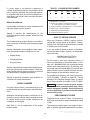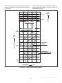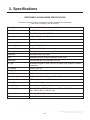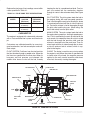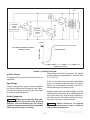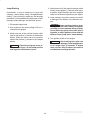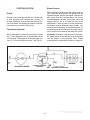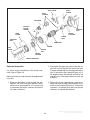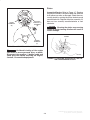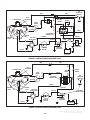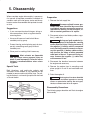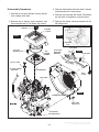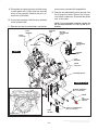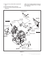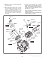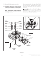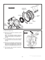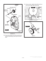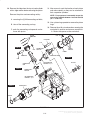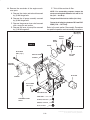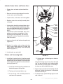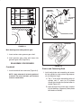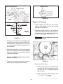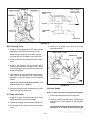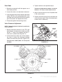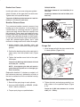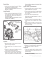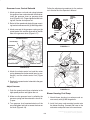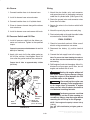
1
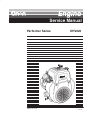
Service Manual ,29389629 -2942: 1867954 67 3$2$, +*/&&$ +*(:%)%%&'#%% # # The engine exhaust from this product contains chemicals known to the State of California to cause cancer, birth defects or other reproductive harm. Redistribution or publication of this document, by any means, is strictly prohibited. 2 .0152 83 (87;27;: SECTION TITLE PAGE SAFETY PRECAUTIONS . . . . . . . . . . . . . . . . . . . . . . . . . . . . . . . . . . . . . . . . . . . iii 1. General Information . . . . . . . . . . . . . . . . . . . . . . . . . . . . . . . . . . . . . . . . . . . . . . 1-1 About this Manual . . . . . . . . . . . . . . . . . . . . . . . . . . . . . . . . . . . . . . . . . . . . . . . Model Number . . . . . . . . . . . . . . . . . . . . . . . . . . . . . . . . . . . . . . . . . . . . . . . . . . How to Obtain Service . . . . . . . . . . . . . . . . . . . . . . . . . . . . . . . . . . . . . . . . . . . Performance Curve . . . . . . . . . . . . . . . . . . . . . . . . . . . . . . . . . . . . . . . . . . . . . . 2. 1-2 1-2 1-2 1-3 Specifications . . . . . . . . . . . . . . . . . . . . . . . . . . . . . . . . . . . . . . . . . . . . . . . . . . . . 2-1 Performer OHV220 Engine Specifications . . . . . . . . . . . . . . . . . . . . . . . . . . Dimensions and Clearances . . . . . . . . . . . . . . . . . . . . . . . . . . . . . . . . . . . . . . ElectricaL Specifications . . . . . . . . . . . . . . . . . . . . . . . . . . . . . . . . . . . . . . . . . . Assembly Specifications . . . . . . . . . . . . . . . . . . . . . . . . . . . . . . . . . . . . . . . . . . Engine oil Recommendation . . . . . . . . . . . . . . . . . . . . . . . . . . . . . . . . . . . . . . Torque Specifications . . . . . . . . . . . . . . . . . . . . . . . . . . . . . . . . . . . . . . . . . . . . 2-1 2-2 2-8 2-8 2-8 2-8 3. Engine Troubleshooting . . . . . . . . . . . . . . . . . . . . . . . . . . . . . . . . . . . . . . . . . . 3-1 4. Engine Systems . . . . . . . . . . . . . . . . . . . . . . . . . . . . . . . . . . . . . . . . . . . . . . . . . . 4-1 Introduction . . . . . . . . . . . . . . . . . . . . . . . . . . . . . . . . . . . . . . . . . . . . . . . . . . . . . Lubrication System . . . . . . . . . . . . . . . . . . . . . . . . . . . . . . . . . . . . . . . . . . . . . . Fuel System . . . . . . . . . . . . . . . . . . . . . . . . . . . . . . . . . . . . . . . . . . . . . . . . . . . . Carburetor . . . . . . . . . . . . . . . . . . . . . . . . . . . . . . . . . . . . . . . . . . . . . . . . . . . . . . Charging System . . . . . . . . . . . . . . . . . . . . . . . . . . . . . . . . . . . . . . . . . . . . . . . . Starting System . . . . . . . . . . . . . . . . . . . . . . . . . . . . . . . . . . . . . . . . . . . . . . . . . 4-1 4-1 4-2 4-3 4-4 4-7 5. Engine Disassembly . . . . . . . . . . . . . . . . . . . . . . . . . . . . . . . . . . . . . . . . . . . . . . 5-1 6. Engine Reassembly . . . . . . . . . . . . . . . . . . . . . . . . . . . . . . . . . . . . . . . . . . . . . . 6-1 Precautions . . . . . . . . . . . . . . . . . . . . . . . . . . . . . . . . . . . . . . . . . . . . . . . . . . . . . 6-1 Special Tools . . . . . . . . . . . . . . . . . . . . . . . . . . . . . . . . . . . . . . . . . . . . . . . . . . . . 6-1 Break–In Operation . . . . . . . . . . . . . . . . . . . . . . . . . . . . . . . . . . . . . . . . . . . . . . 6-1 Pre-Assembly . . . . . . . . . . . . . . . . . . . . . . . . . . . . . . . . . . . . . . . . . . . . . . . . . . . 6-1 Re-assembly Procedures . . . . . . . . . . . . . . . . . . . . . . . . . . . . . . . . . . . . . . . . . 6-3 Final Checks . . . . . . . . . . . . . . . . . . . . . . . . . . . . . . . . . . . . . . . . . . . . . . . . . . . 6-10 Redistribution or publication of this document, by any means, is strictly prohibited. i Safety Precautions Thoroughly read the OPERATOR’S MANUAL before operating the engine. Safe operation and top performance can be obtained only with proper operation and maintenance. • Benzene and lead in some gasolines have been identified by some state and federal agencies as causing cancer or reproductive toxicity. Do not to ingest, inhale or contact gasoline or its vapors. The following symbols in this Manual alert you to potential hazards to the operator, service person and equipment. • Do not work on the engine when mentally or physically fatigued or after consuming alcohol or drugs. alerts you to an immediate hazard which will result in severe personal injury or death. • Carefully follow all applicable local, state and federal codes. alerts you to a hazard or unsafe practice which can result in severe personal injury or death. WARNING This engine is not designed or intended for use in aircraft. Such use can lead to engine failure, severe personal injury or death. WARNING CAUTION alerts you to a hazard or unsafe practice which can result in personal injury or equipment damage. FUEL IS FLAMMABLE AND EXPLOSIVE • Keep flames, cigarettes, sparks, pilot lights, electrical arc-producing equipment and switches and all other sources of ignition well away from areas where fuel fumes are present and areas sharing ventilation. Electricity, fuel, exhaust, moving parts and batteries present hazards which can result in severe personal injury or death. GENERAL PRECAUTIONS • Keep ABC fire extinguishers handy. • Do not fill the fuel tank while the engine is running. • Make sure all fasteners are secure and torqued properly. • Fuel lines must be copper or steel tubing or piping, adequately secured and free of leaks. • Keep the engine and its compartment clean. Excess oil and oily rags can catch fire. Dirt and gear stowed in the compartment can restrict cooling air. • Use approved flexible fuel hose for connections at the engine. Do not use copper tubing as a flexible connector—vibration will cause it to workharden and break. Use non-conductive hose if the fuel line could become a path for cranking current. • Before working on the engine, disconnect the negative (–) battery cable at the battery to prevent starting. • LPG leaks into an inadequately ventilated space can lead to explosive accumulations of gas. LPG sinks when released into the air and can accumulate inside basements and other below-grade spaces. Precautions must be taken to prevent gas leaks and the accumulation of gaseous fuel in the event of a leak. • Use caution when making adjustments while the engine is running—hot, moving or electrically live parts can cause severe personal injury or death. • Used engine oil has been identified by some state and federal agencies as causing cancer or reproductive toxicity. Do not ingest, inhale, or contact used oil or its vapors. • The fuel line must have a manual shutoff valve unless the highest fuel level in the supply tank is lower than the connection at the engine. Redistribution or publication of this document, by any means, is strictly prohibited. ii ENGINE EXHAUST IS DEADLY! BATTERY GAS IS EXPLOSIVE • Wear safety glasses and do not smoke while servicing batteries. • Learn the symptoms of carbon monoxide poisoning in this Manual. • When disconnecting or reconnecting battery cables, always disconnect the negative (–) battery cable first and reconnect it last to reduce arcing. • Inspect the exhaust system every time the engine is started and after every eight hours of operation. If the exhaust noise changes, shut down the engine immediately and have it inspected. MOVING PARTS CAN CAUSE SEVERE PERSONAL INJURY OR DEATH • The integral exhaust system must not be modified in any way. • Do not wear loose clothing or jewelry near moving parts such as PTO shafts, fans, belts and pulleys. • Do not use engine cooling air to heat a room. • Keep hands away from moving parts. • Make sure there is ample fresh air when operating the engine in a confined area. • Keep guards in place over fans, belts, pulleys, etc. e-floorcare Redistribution or publication of this document, by any means, is strictly prohibited. iii Redistribution or publication of this document, by any means, is strictly prohibited. iv 1. General Information Introduction • A steel crankshaft and high-load bearing offer durability. This manual deals with specific mechanical and electrical information needed by engine mechanics for troubleshooting, servicing, repairing, or overhauling the engine. • Pressure lubrication system and large capacity air cleaner enhance reliability of the engine. The Parts Manual contains detailed exploded views of each assembly and their individual piece part numbers and names for ordering replacement parts. • The combustion chamber shape, along with a tuned exhaust valve system, enhances the low exhaust emission and provides high torque at low speed. Features of the Performer OHV220 engine are: A steel crankshaft and high-load bearing offer durability. The pressure lubrication system and large capacity air cleaner enhance reliability of the engine. • Overhead valve arrangement enables high power and low fuel and oil consumption • V-twin, four stoke design The illustrations and procedures presented in each section apply to the Performer OHV220 Engine. The blower housing side of the engine is the front end. Right and left sides are determined by viewing the engine from the front. The No. 1 cylinder is on the right; the No. 2 cylinder is on the left (Figure 1-1). • Air-cooled and gasoline fueled • The light-weight and compact design make it easy to install and utilize for many applications. Oil Fill Cap Dip Stick Carrier Speed Control Solenoid (Optional) Air Cleaner Cover Spark Plug Carrier Spark Plug Oil Filter PTO Shaft Voltage Regulator Oil Drain Valve Blower Housing Starter Motor & Solenoid FRONT VIEW REAR VIEW FIGURE 1-1. PERFORMER OHV220 ENGINE 1-1 Redistribution or publication of this document, by any means, is strictly prohibited. If a major repair or an overhaul is necessary, a trained, experienced mechanic should either do the job or supervise and check the work of the mechanic assigned to the job to ensure that all dimensions, clearances, and torque values are within the specified tolerances. TABLE 1-1. ENGINE MODEL NUMBER P 220 GI OHV XXX A | | | | | | 1 2 3 4 5 6 1. Model Letter – Performer 2. Number of Cylinders and Rated Horse Power A. “220” designates 2 Cylinders at 20 HP 3. Engine Fuel Type and Engine Type – Gas Industrial 4. Engine Type – Overhead Valves 5. Engine Specific Model Number 6. Model Nomenclature Revsion About this Manual Use the table of contents for a quick reference to the separate engine system sections. Section 2 contains the specifications for the OHV220 engine for fluids, torques, clearances and tolerances. HOW TO OBTAIN SERVICE When the Performer 220OHV requires service, contact the nearest dealer or distributor. Factorytrained Parts and Service representatives are ready to handle your service needs. The troubleshooting guide in Section 3 provides a quick reference for locating and correcting engine troubles. If you are unable to locate a dealer or distributor, consult the Yellow Pages. Typically, our distributors are listed under: Section 4 describes various engine system operations and contains electrical diagrams for the: • Engine Wiring GENERATORS-ELECTRIC or ELECTRICAL PRODUCTS • Charging System For the name of your local Cummins/Onan or Onan-only distributor in the United States or Canada, call 1-800-888-ONAN (this automated service utilizes touch-tone phones only). By entering your area code and the first three digits of your local telephone number, you will receive the name and telephone number of the distributor nearest you. • Starter System. Section 5 describes the engine disassembly procedure when performing a major overhaul. The procedure provides step-by-step instructions for removal and disassembly of engine components. For outside North America, call Onan Corporation, 1-612-574-5000, 7:30 AM to 4:00 PM, Central Standard Time, Monday through Friday. Or, send a fax to Onan using the fax number 1-612-574-8087. Section 6 describes inspection and assembly instructions for engine components. MODEL NUMBER Incorrect service or parts replacement can result in severe personal injury, death, and/or equipment damage. Service personnel must be qualified to perform electrical and/or mechanical service. WARNING Use only Genuine Onan" replacement parts to for quality and the best possible repair and overhaul results. PERFORMANCE CURVE Whenever contacting an dealer or distributor for information, parts or service, always provide the model number and the serial number marked on the nameplate of the engine. The power curve shown in Figure 1-2 conforms to SAE internal combustion engine standard test code J1349. See Table 1-1 for an explaination of the engine model number. The continuous rated output is the output of an engine at optimum governed speed which is prefera- 1-2 Redistribution or publication of this document, by any means, is strictly prohibited. ble for engine life and fuel consumption. When the engine is installed, the rated output should be lower than shown. The maximum torque is the torque rated on the output shaft while the engine is running at maximum output per revolution. 35 ( 3.57) MAXIMUM TORQUE TORQUE 45 ( 4.59) N–m ( kgf–m) MAXIMUM HORSEPOWER 15 ( 20.1) HORSEPOWER kW (HP) CONTINUOUS RATED HP 10 ( 13.4) RECOMMENDED HORSEPOWER RANGE 5 ( 6.7) 2000 2400 2800 3200 REVOLUTION 3600 r.p.m FIGURE 1-2. OHV220 PERFORMANCE CURVE 1-3 Redistribution or publication of this document, by any means, is strictly prohibited. 1-4 Redistribution or publication of this document, by any means, is strictly prohibited. 2. Specifications PERFORMER OHV220 ENGINE SPECIFICATIONS This Manual contains SI metric equivalents that follow immediately in parentheses after the U.S. customary units of measure. Engine Type 4-Cycle, V-Twin Cylinder, Horizontal Shaft, Overhead Valve, Rated Output 20.5 HP/3600 rpm (15.3 kW/3600) Continuous Output 16.0 HP/3600 rpm (11.9kW/3600) Bore x Stroke 3.15” x 2.56” (80 mm x 65 mm) Displacement 39.90 cu in (653 cc) Compression Ratio 8.3:1 Maximum Output 15.3 kW / 20.5 HP / 3,600 rpm Maximum Torque 32.7 ft/lbs @ 2,200 rpm Starting System Electric Start Carburetor Horizontal Shaft, Float Type Fuel Unleaded Gasoline using a Diaphragm Pulse Pump Lubrication Full Pressure with Full Flow Spin-On Filter Oil Type Automobile Engine Oil SAE Class SE or Higher (See Engine Oil Recommendation) Oil Capacity 1.64 qt (1550 cc) Charging System 12 volt 15 amp Dry Weight 96.9 lbs (44 kg) Dimensions (LxWxHx) 12.5” x 19.0” x 19.0” (317 mm x 477 mm 475 mm) Direction of Rotation CCW as Viewed from the PT shaft side Cooling System Forced Air Cooling Ignition System Flywheel Magneto (Solid State) Spark Plug Type NGK–BP6ES or BRP6ES (Champion – N9YC or RN9YC) Gap: 0.023–0.027 in (.0.6–0.7 mm) Governor System Centrifugal Fly Weight Air Cleaner Double Element Assembly 2-1 Redistribution or publication of this document, by any means, is strictly prohibited. DIMENSIONS AND CLEARANCES STANDARD inches (mm) MAXIMUM inches (mm) 0.002 or less (0.05 or less) 0.004 (0.1) 0.028 – 0.039 (0.7 – 1.0) 0.079 (2.0) 0.2376 – 0.2383 (6.035 – 6.053) 0.242 (6.15) STD 3.1496 – 3.1504 (80.000 – 80.019 Rebore when the difference between the max. and min. of diameter reaches 0.004 (0.1) 1st Reboring 3.159 – 3.160 (80.250 – 80.269) 3.159 – 3.160 (80.250 – 80.269) 2nd Reboring 3.169 – 3.170 (80.500 – 80.519) –––––––– Roundness after reboring 0.004 (0.01) –––––––– Cylindricity after reboring 0.0006 (0.015) –––––––– ITEM Cylinder Head Flatness Intake/ Exhaust Valve seat contact width Valve guide inside diameter Cylinder Inside diameter ÇÇÇ ÇÇÇ ÇÇÇ ÇÇÇ ÇÇÇ ÇÇÇ ÇÇÇ ÇÇÇ ÇÇÇ ÇÇÇ ÇÇÇ ÇÇÇ ÇÇÇ ÇÇÇ 2-2 Redistribution or publication of this document, by any means, is strictly prohibited. STANDARD inches (mm) MAXIMUM inches (mm) STD 3.148 – 3.149 (79.968 – 79.988) 3.145 (79.878) 1st outer diameter 3.158 – 3.159 (80.218 – 80.238) 3.155 (80.128) 2nd outer diameter 3.168 – 3.169 (80.468 – 80.488) 3.164 (80.378) Top 0.0002 – 0.0035 (0.05 – 0.09) 0.006 (0.15) 2nd 0.0012 – 0.0028 (0.03 – 0.07) 0.006 (0.15) Oil Ring 0.0022 – 0.0069 (0.057 – 0.175) 0.006 (0.15) Piston pin hole 0.8262 – 0.8269 (20.989 – 21.002) 0.8281 (21.035) Piston pin outer diameter 0.8264 – 0.8268 (20.991 – 21.000) 0.8251 (20.960) 0.0005 – 0.0020 (0.012 – 0.051) 0.0098 (0.25) ITEM 16 mm Piston Piston size (at skirt in thrust direction) ÇÇÇ ÇÇÇ ÇÇÇ ÇÇÇ Ring groove side clearance Clearance between piston and cylinder at skirt area ÇÇÇ ÇÇÇ ÇÇÇ ÇÇÇ ÇÇÇ ÇÇÇ ÇÇÇ ÇÇÇ ÇÇÇ ÇÇÇ ÇÇÇ ÇÇÇ 2-3 Redistribution or publication of this document, by any means, is strictly prohibited. STANDARD inches (mm) MAXIMUM inches (mm) Top 2nd 0.0079 – 0.0157 (0.2 – 0.4) 0.0591 (1.5) Oil Ring 0.0079 – 0.0276 (0.2 – 0.7) 0.0591 (1.5) 1.5354 – 1.5361 (39.000 – 39.016) 1.5394 (39.100) 0.0012 – 0.0024 (0.030 – 0.060) 0.0079 (0.2) 0.8272 – 0.8277 (21.010 – 21.023) 0.8299 (21.080) Clearance between piston pin and inner diameter 0.0004 – 0.0013 (0.010 – 0.032) 0.0047 (0.12) Large end side clearance 0.0039 – 0.0157 (0.1 – 0.4) 0.0394 (1.0) ITEM Piston (continued) Piston ring end gap Connecting Rod ÇÇÇ ÇÇÇ ÇÇÇ ÇÇÇ ÇÇÇ ÇÇÇ ÇÇÇ ÇÇÇ ÇÇÇ ÇÇÇ ÇÇÇ Large end inner diameter &'%# Clearance between crankpin and inner diameter Small end inner diameter 2-4 Redistribution or publication of this document, by any means, is strictly prohibited. ITEM STANDARD inches (mm) MAXIMUM inches (mm) 1.5337 – 1.5343 (38.956 – 38.970) 1.5315 (38.90) Crankshaft Crankpin outer diameter D1: 1.77102 – 1.77165 (44.984 – 45.000) Journal diameter D2: 1.77110 – 1.77154 (44.986 – 44.997) ––––––– Camshaft Cam height (internal and external) Journal outer diameter “D” D 1.4213 – 1.4291 (36.1 – 36.3) 1.4154 (35.95) 0.7861 – 0.7866 (19.967 – 19.980) 0.7854 (19.950) Intake 0.2350 – 0.2356 (5.970 – 5.985) 0.2303 (5.85) Exhaust 0.2346 – 0.2352 (5.960 – 5.975) 0.2303 (5.85) Intake 0.0022 – 0.0033 (0.050 – 0.083) 0.0118 (0.30) Exhaust 0.0024 – 0.0037 (0.060 – 0.093) 0.0118 (0.30) D Valve Valve stem outer diameter Clearance between valve stem and valve stem guide 2-5 Redistribution or publication of this document, by any means, is strictly prohibited. STANDARD inches (mm) ITEM MAXIMUM inches (mm) Valve (continued) Intake/ Exhaust Measured Cold Valve clearance 0.0034 – 0.0045 (0.085 – 0.115) Valve spring 1.5551 (39.5) ––––––– Outer stem diameter 0.03528 – 0.3533 (8.960 – 8.975) 0.3516 (8.93) Inner guide diameter 0.3543 – 0.3549 (9.00 – 9.015) 0.3575 (9.08) 0.0010 – 0.0022 0.025 – 0.055) 0.0059 (0.15) a: 45# b: 0.028 – 0.039 (0.7 – 1.0) 0.079 (2.0) Free length Tappet Tappet guide clearance ÇÇÇÇÇÇÇÇÇ ÇÇÇÇÇÇÇÇÇ ÇÇÇÇÇÇÇÇÇ ÇÇÇÇÇÇÇÇÇ ÇÇÇÇ Valve seat angle Cut angle (a) Contact width (b) a 2-6 Redistribution or publication of this document, by any means, is strictly prohibited. STANDARD inches (mm) MAXIMUM inches (mm) Shaft diameter 0.4719 – 0.4722 (11.986 – 11.994) 0.4693 (11.92) Rocker arm hole diameter 0.4727 – 0.4734 (12.006 – 12.024) 0.4752 (12.07) 0.0005 – 0.0015 (0.012 – 0.038) 0.0059 (0.15) ITEM Rocker Arm Arm shaft clearance ÉÉ ÉÉ ÉÉ 2-7 Redistribution or publication of this document, by any means, is strictly prohibited. After the first 20 hours of operation the initial oil and oil filter should be replaced. ELECTRICAL SPECIFICATIONS COMPONENT RATING Voltage Regulator Output CAUTION Used engine oil has been identified by some state and federal agencies as causing cancer or reproductive toxicity. Do not ingest, inhale, or contact used oil or its vapors. 12V 15 Amp Ignition Coil Resistance Primary Secondary 7.8 Ohms Charge Coil Nominal Output Resistance 7.8 Ohms Thereafter, change the oil every 100 hours of operation and change the oil filter every 200 hours. 12V 15 Amp TORQUE SPECIFICATIONS 9 ohms ITEM TORQUE Ignition coil air gap 0.012 – 0.020” (0.3 – 0.5 mm) Breather cover Fuel Pump At low idle Inlet vacuum 2.6” of mercury Carburetor bolts Outlet pressure 1.7 psi Charge coil At high idle Inlet vacuum 2.6” of mercury Connecting rod bolts (minimum measurements) Outlet pressure 1.7 psi 16.3 – 19.9 ft/lbs (22.1 – 27.0 N"m) Cylinder head bolts 24.6 – 30.4 ft/lbs (33.3 – 41.2 N"m) Flywheel nut 61.5 – 68.7 ft/lbs (83.3 – 93.1 N"m) ASSEMBLY SPECIFICATIONS COMPONENT End play between crankshaft and camshaft 0.006 – 0.013” (0.152 – 0.330mm) 0.014” (0.36mm) Clearance between rocker arm and valve stem end 0.003 – 0.004” (0.085 – 0.115mm) Clearance between ignition coils and flywheel 0.012 – 0.020” (0.3 – 0.5mm) 5.1 – 6.6 ft/lbs (6.9 – 8.8 N"m) Intake manifold nuts & Main bearing cover bolts 12.3 – 13.7 ft/lbs (16.7 – 18.6 N"m) Oil filter 9 ft/lbs (12.3 N"m) Oil pressure switch SAE VISCOSITY GRADE 32° F (0° C) and higher 30 10° F to 100° F (–12° C to 38° C) 15W-40 10.9 – 18.1 ft/lbs (11.8 – 14.7 N"m) Rocker arm nut 7.2 – 10.1 ft/lbs (9.8 – 13.7 N"m) Rocker arm cover 26.4 – 43.2 in/lbs (2.9 – 4.9 N"m) Spark plug: new 8.7 – 10.9 ft/lbs 11.8 – 14.7 N"m) Used (OnaMax) 0° F to 80° F (–18° C to 27° C) 10W-30 10W-40 –20° F to 50° F (–28° C to 10° C) 5W-30 Starter motor bolts 2-8 4.3 – 7.2 ft/lbs (5.9 – 9.8 N"m) Oil relief plug ENGINE OIL RECOMMENDATION EXPECTED AMBIENT TEMPERATURES 12.3 – 13.7 ft/lbs (16.7 – 18.6 N"m) 13.2 – 30 in/lbs (1.5 – 3.4 N"m) Ignition coil CLEARANCE Clearance between crankcase and bearing cover 26.4 – 43.2 in/lb (2.9 – 4.9 N"m) 16.6 – 19.5 ft/lbs (22.5 – 26.5 N"m) 12.3 – 13.7 ft/lbs (16.7 – 18.6 N"m) Redistribution or publication of this document, by any means, is strictly prohibited. 3. Engine Troubleshooting WARNING Many troubleshooting procedures present hazards that can result in severe personal injury or death. Only qualified service personnel with knowledge of fuels, electricity, and machinery hazards should perform service procedures. Review the safety precautions on the inside cover page. Problem Starter does not operate Starter operates but engine does not start Low engine speed while cranking WARNING Hot engine parts can cause severe burns. Always allow the engine time to cool before performing any maintenance or service. Refer to other sections within this manual or the Operators Manual for procedures to test, adjust, repair or replace engine components. Possible Cause Remedy Poor connection of key or starter switch wiring Check, repair or replace Discontinuity between key switch or start switch and starter motor Replace wiring Discontinuity between battery and starter motor Replace battery cables Weak or low charged battery Charge or replace battery Poor battery terminal connections Check and clean terminals, replace if damaged Faulty solenoid switch Check, repair or replace Faulty starter motor Repair or replace starter Crankshaft has seized Check crankshaft bearings and crankshaft bearing surface A piston and cylinder have seized Check pistons and cylinder bores No fuel in system Refill Poor connection or discontinuity of ignition system wires Check wire connections and ignition coils for shorts Faulty starter motor Slow cranking RPM caused by a faulty starter motor or low battery voltage at starter Low battery Charge battery Bad connection between battery and starter motor Clean or repair Bad connection between battery and ground Clean or repair Starter motor has worn brushes or bearing Repair or replace starter motor Improper engine oil Replace with recommended engine oil 3-1 Redistribution or publication of this document, by any means, is strictly prohibited. Problem Possible Cause Spark plug: Improper gap No insulator Carbon deposits Ignition system malfunctions Fuel system malfunctions Adjust Replace Clean Ignition coil No insulation or discontinuity Bad connection or discontinuity of ignition coil Check for grounded wire and replace Replace coil(s) Improper air gap between ignition coil and flywheel Check and adjust Fuel tank is empty Refill tank Fuel pump is plugged up Disassemble and clean Fuel hose is plugged or pinched Check lines, replace if necessary Air is mixing into fuel lines Check and tighten connections Plugged fuel filter or air infiltration Clean or replace fuel filter Carburetor Flooding Clogged or damaged Throttle valve not functioning Low fuel flow to carburetor Low compression/ Insufficient output Remedy The floats are sticking Disassemble and clean Check throttle shaft and linkage, adjust governor lever Faulty fuel cut-off valve or wiring Engine idles too high Adjust or replace control solenoid Idle unstable Check govenor linkage and springs Loose spark plug(s) Retighten or replace plug wire Head gaskets are leaking Retighten or replace gasket Worn piston ring(s) or seizure Replace ring(s) Incorrect valve and seat contact Adjust or replace Valve stem seizure Repair or replace Incorrect valve clearance Check and adjust Ignition coil(s) faulty Check and replace Improper gap between coil and flywheel Check and adjust Charge coil is demagnetized Replace charge coil Fuel system problems Check system Low air intake Clean air cleaner elements Check throttle valve for full opening 3-2 Redistribution or publication of this document, by any means, is strictly prohibited. Problem Overheating High oil consumption Pre-Ignition Possible Cause Remedy Cooling air flow obstructed Check air inlet and cylinder baffle and clean out Improper engine oil Replace Lean air/fuel mixture Check for plugged passages in carburetor Excessive back pressure of exhaust system Check, clean or replace muffler and spark arrestor (if equipped) Engine is overloaded Change to rated load Oil is leaking Loose drain valve or gasket Filter not properly installed Bearing cover bolts are loose Bearing cover gasket is worn or damaged Check and replace gaskets if necessary Oil is diluted Piston oil rings are faulty Piston rings worn, siezed or making poor contact Piston and cylinder are worn Valve stem is worn Oil level is too high Cylinder breather is faulty Replace piston rings Hone cylinders and install oversize piston rings Replace valve guides Adjust oil level Replace breather cover assembly Ignition sytem faulty Ignition system wiring is poor Improper or damaged spark plug(s) Check wiring and connections Clean or replace Fuel system malfunction Lean air/fuel mixture Carburetor damaged Fuel lines clogged or damaged Vacuum leak Check for plugged carburetor Disassemble and clean Clean or replace Replace gaskets Cylinder head Carbon deposit in combustion chamber Cylinder head gasket leaking Valve system Improper valve clearance Valve heat deterioration Valve spring deterioration 3-3 Remove and clean out carbon Replace gasket Adjust valve lash Replace or regrind Replace springs Redistribution or publication of this document, by any means, is strictly prohibited. Problem Possible Cause Ignition system Improper spark plug gap or damaged plug Faulty ignition coil Damaged or poor connection of ignition wires Engine misfire Remedy Clean, adjust or replace Replace coil(s) Check connections or replace wires Fuel system Lean air/fuel mixture due to clogged Disassemble and clean carburetor carburetor Replace gasoline and filter Improper gasoline or water infiltration Engine valves Valves are deteriorated or out of adjustment Valve spring is faulty 3-4 Adjust or replace valves Replace springs Redistribution or publication of this document, by any means, is strictly prohibited. 4. Engine Systems in the bottom of the crankcase. A relief valve is used to control oil pressure. INTRODUCTION This section presents an overview of the following OHV220 engine systems. Oil Pump Operation • Lubrication System A large trochoid type oil pump is driven directly by the crankshaft, delivering pressurized oil to the journal and pin portions of crankshaft, camshaft etc. • Fuel System • Electrical System A cartridge type oil filter is located in the bottom of the crankcase. Through this cartridge oil filter, oil is forced onto rotating parts such as journal and pins of the crankshaft and camshaft. • Starting System LUBRICATION SYSTEM Oil is fed through the oil pump filter into the oil pump. The oil pressure is adjusted by the relief valve after discharging from oil pump. Oil is then splashed onto the cylinder, piston, and the cylinder head valve system. See Figure 4-1. Oil and Filter Change Refer to Periodic Maintenance in the Operator’s Manual for oil and filter change intervals and procedures. A by-pass valve is incorporated into the cartridge type oil filter. In the event the oil filter element becomes clogged, the engine oil is fed through the bypass valve into the crankcase oil passage. Pressure Lubrication All engines use an oil pump to provide a constant flow of oil to the engine parts. The oil supply collects OIL FILTER CAMSHAFT CRANKSHAFT RELIEF VALVE OIL PUMP OIL PUMP FILTER FIGURE 4-1. LUBRICATION SYSTEM 4-1 Redistribution or publication of this document, by any means, is strictly prohibited. Relief Valve Ignition of fuel can result in severe personal injury or death. Thoroughly clean up any spilled fuel. Do not smoke or allow any flame, spark, pilot light, or arcing switch or equipment, or other source of ignition near the work area or areas sharing ventilation. WARNING The relief valve is located on the bottom of the crankcase. It is non-adjustable and normally does not require maintenance. However, each part of the relief valve is replaceable. Oil Pressure Switch 1. Operate the engine at an idle for five minutes until the carburetor is full of fuel. The oil pressure switch is mounted on the same housing as the oil filter. If oil pressure becomes low while flowing to the oil pump, the switch will trigger a shutdown condition. 2. Shut the engine off and remove the fuel supplyline from the fuel pump. 3. Connect a vacuum gauge to the fuel pump inlet using a piece of fuel hose with clamps. Crankcase Breather 4. Start the engine and allow to idle for at least five seconds. Record the vacuum gauge reading. The crankcase breather prevents pressure from building up in the crankcase. It also prevents oil contamination by removing moisture or gasoline vapors and other harmful blow-by materials from the crankcase. These vapors are routed to the carburetor where they are mixed with incoming air and burned in the combustion chamber. 5. Move the throttle control to the high idle position. Wait at least five seconds and record the vacuum gauge reading. 6. Shut the engine off and remove the vacuum gauge hose from the fuel pump inlet. Connect the fuel inlet line to the fuel pump. A sticky breather valve can cause oil leaks, high oil consumption, rough idle, reduced engine power, and a rapid formation of sludge and varnish within the engine. 7. Shut the engine off and remove the pressure gauge hose from the fuel pump outlet. Connect the fuel outlet line to the fuel pump. Replace the breather if it’s broken or cracked, or if the crankcase becomes pressurized indicated by oil leaks at the seals or excessive oil in the air cleaner housing. Benzene and lead in some gasolines have been identified by some state and federal agencies as causing cancer or reproductive toxicity. Do not to ingest, inhale or contact gasoline or its vapors. WARNING FUEL SYSTEM 8. Remove the fuel outlet line from the fuel pump. The fuel system consists of a fuel pump, carburetor, fuel filter, shut-off valve and control linkage. 9. Connect a pressure gauge to the fuel pump outlet using a piece of fuel hose with clamps. 10. Start the engine and allow to idle for at least five seconds. While holding the pressure gauge level with the pump outlet, record pressure gauge reading. Fuel Pump A diaphragm type fuel pump is mounted on the front of the engine. The pump is operated by vacuum pressure inside the crankcase. 11. Move the throttle control to the high idle position and allow the engine to run for at least five seconds. While holding the pressure gauge level with the pump outlet, record pressure gauge reading. The fuel pump is not serviceable and should be replaced if faulty. Fuel Pump Test Procedure 12. Shut the engine off and remove the pressure gauge hose from the fuel pump outlet. Connect the fuel outlet line to the fuel pump. Before testing, make certain the fuel pump vacuum and fuel line connections are tight and free of leaks. 4-2 Redistribution or publication of this document, by any means, is strictly prohibited. Replace the fuel pump if test readings are not within values specified in Table 4-1. keeping the fuel at a predetermined level. Fuel vapors are sucked into the combustion chamber through air vents in the carburetor body. See Figure 4-2. TABLE 4-1. PULSE PUMP TEST SPECIFICATIONS ENGINE SPEED PUMP INLET VACUUM (Minimum) PUMP OUTLET PRESSURE (Minimum) Low Idle 2.6 inches of mercury 1.7 psi High Idle 2.6 inches of mercury 1.7 psi PILOT SYSTEM The pilot system feeds the fuel to the engine during idle and low-speed operation. Fuel is fed through the main jet to the pilot jet, where it is metered and mixed with the air from the pilot air jet. The fuel/air mixture is fed to the engine through the pilot outlet and the by-pass. When idling, the fuel is fed mainly from the pilot outlet. Carburetors are calibrated carefully for sure starts, good acceleration, low fuel consumption and sufficient output. MAIN SYSTEM The main system feeds the fuel to the engine during medium- and high-speed operation. Fuel is metered by the main jet and fed to the main nozzle. Air metered by the main air jet is mixed with the fuel through the emulsion tube, and the mixture is atomized out of the main bore. Then it’s mixed again with the air taken through the air cleaner into an optimum fuel-air mixture, which is supplied to the engine. FLOAT SYSTEM Fuel flows from the fuel tank into the float chamber through a needle valve. When the fuel rises to a specific level, the float rises. When its buoyancy and fuel pressure are balanced, the needle valve closes to shut off the fuel, thereby CHOKE The choke is used for easy start-up when the engine is cold. When the starter is operated with a choke valve fully closed, the negative pressure applied to the main nozzle increases and draws more fuel; thus easily starting the engine. CARBURETOR The engine is equipped with a down draft carburetor with a float-controlled fuel system and fixed main jet. CHOKE VALVE AIR AIR VENT HOLE PILOT AIR JET MAIN AIR JET EMULSION TUBE FLOAT NEEDLE VALVE SHUT-OFF VALVE FUEL MAIN JET FUEL INLET PIPE MAIN NOZZLE TAMPER CAP PILOT JET THROTTLE VALVE BY–PASS MIXTURE PILOT OUTLET FIGURE 4-2. CARBURETOR SYSTEM 4-3 Redistribution or publication of this document, by any means, is strictly prohibited. SHUT-OFF VALVE A fuel shut-off valve prevents engine run-on when the engine is turned off. When the engine is on, the valve is activated and the plunger is pulled in to open the main jet. When the engine is off, the power source to the valve is off. The plunger is pushed out by the return spring and stops the fuel flow to the main jet. CHARGING SYSTEM Magneto Carburetor Replacement The ignition system contains a flywheel magneto with automatic advancing characteristics. This system is free from start-up failure due to dirty, burnt or a corroded point surfaces because there are no points. Do not adjust the fuel mixture, rebuild or overhaul the carburetor. A malfunctioning carburetor should be replaced. Before replacing a carburetor, however, make certain that: The electronic automatic advancing provides easy starts and stable high performance at operating speed by advancing the ignition timing to the most suitable point. • All other necessary engine and generator adjustments and repairs have been performed THEORY: Refer to Figure 4-3. Revolution of the flywheel generates electricity on the primary side of the ignition coil, and the base current )# to the power transistor. Current )# turns the power transistor “on” and the electric current )$ flows. • The carburetor is actually malfunctioning (see Section 3: Engine Troubleshooting). During low idle, after the flywheel reaches the ignition point, the low speed ignition timing control circuit runs the base current )% turning the signal transistor A “on”. This allows the current )# to bypass as current )&. The power transistor turns “off” and the current )$ is abruptly shut, resulting in high voltage generated in the secondary coil producing sparks at the spark plugs. CAUTION Unauthorized modifications or replacement of fuel, exhaust, air intake, or speed control system components that affect emission on California certified engines are prohibited by law in the State of California. To remove the carburetor, remove the air cleaner, disconnect the fuel line, choke, and throttle linkages, and unbolt the carburetor from the intake manifold. When reinstalling the carburetor, always use a new gasket. Readjust the choke and throttle cables and engine speed as instructed in the Operator’s Manual. During high speed operation, the advancing control circuit operates the ignition timing to run base current )' turning the signal transistor B “on”. This allows current )# to bypass as current )(. The power transistor turns “off” and the current )$ is abruptly closed, resulting in high voltage generated in the secondary coil producing sparks at the spark plugs. Speed Control Solenoid (Optional) The speed control solenoid monitors the rate of the load and automatically adjusts the engine to the appropriate idle speed. The engine timing advances relative to the engine speed controlled by this circuit. This timing advance system is contained within the magneto coils and is not serviceable nor can the individual electronic components be replaced. The solenoid is faulty if the idle does not pull to low. Replace the solenoid. 4-4 Redistribution or publication of this document, by any means, is strictly prohibited. I4 Spark Plug I5 Secondary Coil B Automatic Advancing Control Circuit Signal Transistor I3 Signal Transistor Low Speed Ignition Timing Control Circuit Primary Coil Power Transistor Resistor A I1 I2 I6 ( B.T.D.C. ) STEP ADVANCING IGNITION TIMING ELECTRONIC ADVANCING FLYWHEEL MAGNETO SYSTEM 500 1000 2000 3000 (r.p.m.) ENGINE REVOLUTION FIGURE 4-3. MAGNETO SYSTEM Check battery cells with a hydrometer. The specific gravity reading should be between 1.260 and 1.290 at 77°F (25°C). Ignition TIming The ignition timing is preset at the factory and is not adjustable. If one or more cells are low on water, add distilled water and recharge. Keep the battery case clean and dry. An accumulation of moisture or dirt will accelerate discharge and battery failure. Spark Plugs Check or replace spark plugs as recommended in the Periodic Maintenance Schedule in the Operator’s Manual. Replace spark plugs that show signs of fouling or electrode erosion. Keep the battery terminals clean and tight. Push the cable terminal down flush with or slightly below the top of the battery post. After making connections, coat the terminals with a light application of petroleum jelly or grease to retard corrosion. Battery Inspection WARNING Battery gas is explosive. Wear safety glasses and do not smoke while servicing batteries. Lead acid batteries give off a highly explosive hydrogen gas which can be ignited by flame, electrical arcing or smoking. Always disconnect the negative cable first, and reconnect it last to reduce the risk of arcing and explosion. WARNING 4-5 Redistribution or publication of this document, by any means, is strictly prohibited. 4. Attach one end of the negative booster cable (black) to the negative (–) terminal of the booster battery. Attach the other end of the negative cable to a solid chassis ground on your engine. Jump Starting Occasionally, it may be necessary to jump start (charge) a weak battery using a charged booster battery. If jump starting is necessary, the following procedure is recommended to help prevent starter damage, battery damage, and personal injuries. 5. Jump starting in any other manner may result in damage to the battery or the electrical system. 1. Disconnect engine load. Jump starting a battery incorrectly can cause either battery to explode, resulting in severe personal injury or death. Do not allow any spark, flame, pilot light, lit cigarette, or other ignition sources near the battery. Do not jump start a frozen battery. WARNING 2. Use a battery of the same voltage (12V) as is used with your engine. 3. Attach one end of the positive booster cable (red) to the positive (+) terminal of the booster battery. Attach the other end on the positive cable to the positive (+) terminal of your engine battery. 6. Turn ignition switch to start engine. CAUTION Overcranking the engine can cause starter damage. Do not engage starter for longer than 30 seconds. If engine does not start, allow 5 minutes for starter to cool between cranking intervals. WARNING Electrical arcing can cause severe personal injury. Do not allow positive and negative cable ends to touch. 4-6 Redistribution or publication of this document, by any means, is strictly prohibited. STARTING SYSTEM Starter Service When starting the engine, note the starter motor action. The pinion gear should mesh quickly with the flywheel ring gear and spin the engine. Once the engine starts and the solenoid opens, the starter should disengage and stop. If the starter cranks the engine slowly, or not at all, check the start circuit components. Failure to crank is usually caused by a low battery charge, defective battery cables, corroded or poor connections, or low temperatures. After checking these variables and the starter continues to crank slowly, remove and repair the starter. Starter Normally, the starter requires little or no service other than possible brush replacement. However, if through accident or misuse, the starter requires service or overhaul, the following provides the information necessary to perform this service. Functional Operation Assembly: Assembly is the reverse of disassembly. Apply grease to the shift fork hinge and prongs and the splines on the armature shaft. Torque mounting bolts as specified in Section 2, page 2-8. When the engine is turned ON, low electric current (M #) flows through the coil of the solenoid and the coil is excited. The plunger is pulled and higher current (S #) flows through the starter. See Fig 4-4 STARTER MOUNTED SOLENOID CUSTOMER CONNECTION FIGURE 4-4. STARTING SYSTEM DIAGRAM 4-7 Redistribution or publication of this document, by any means, is strictly prohibited. SHIFT LEVER DUST COVER DUST COVERS SOLENOID BRUSH & BRUSH SPRING CHARGE COIL REAR COVER PINION STOPPER PINION ASSY. THROUGH BOLT ARMATURE FRAME DUST COVER BRUSH SET BRUSH HOLDER THRUST WASHERS FIGURE 4-5. STARTER ASSEMBLY Before removing a starter because the engine does not crank: 2. Disconnect the spark plug cable so that the engine will not start. Bypass the start circuit with a jumper between the start and the positive battery (+) terminal on the solenoid (Figure 4-6). If the engine cranks, the solenoid and starter are probably okay. If the engine does not crank, go to Step 3. 1. Make sure the battery is fully charged, the connections are clean and tight and the battery cables are in good condition. If it is necessary to reconnect the battery, connect the positive (+) battery cable first. 3. Bypass the starter solenoid with a jumper between the motor and the positive battery (+) terminal on the solenoid (Figure 4-6). If the motor responds, it is probably okay and it may only be necessary to replace the solenoid. Solenoid Inspection For typical wiring connections at the starter solenoid, refer to Figure 4-6. 4-8 Redistribution or publication of this document, by any means, is strictly prohibited. Pinion START TERMINAL (B) Inspection/Service: Refer to Figure 4-7. Replace the pinion assembly if the pinion teeth and armature shaft splines are worn or damaged. Check the overrunning clutch by rotating the pinion clockwise and counterclockwise. Replace the pinion assembly if it does not turn smoothly counterclockwise or lock clockwise. BATTERY POSITIVE (+) TERMINAL (A) CAUTION Cleaning the pinion over-running clutch in liquid cleaning solution will result in starter damage. 1./.0/ MOTOR TERMINAL (C) FIGURE 4-6. STARTER SOLENOID TERMINALS WARNING Accidental starting of the engine can result in severe personal injury or death. Disconnect the negative (–) battery cable and spark plug wire before servicing the engine, controls, or associated equipment. )-<%''& FIGURE 4-7. CHECKING OPERATION OF THE PINION OVER-RUNNING CLUTCH 4-9 Redistribution or publication of this document, by any means, is strictly prohibited. OIL PRESSURE SWITCH RED RED WHITE BLUE RELAY BLACK YELLOW BLACK RED YELLOW BLACK GRAY CUSTOMER CONNECTION CHARGE COIL IGNITION COILS BYPASS DIODE BLUE STOP DIODE BLACK CARBURETOR BLUE FUEL SOLENOID VOLTAGE REGULATOR GREEN GREEN BLACK RED FUSE BLACK STARTER MOTOR BLACK CONTROL SOLENOID STARTER SOLENOID BATTERY 12V 30 AH FIGURE 4-8 ENGINE WIRING DIAGRAM (6 PIN) FUEL SOLENOID WHITE BLACK GREEN CHARGE COIL OIL PRESSUR E SWITCH YELLOW VOLTAGE REGULATOR CUSTOMER CONNECTIONS BLACK BLACK BLACK RED CUSTOMER CONNECTION YELLOW BLACK BYPASS DIODE RUN DIODE RED STOP DIODE BLACK CARBURETOR IGNITION COILS RED RED RED RED STARTER MOTOR STARTER SOLENOID BATTERY 12V 30 AH FIGURE 4-9 ENGINE WIRING DIAGRAM (4 PIN) 4-10 Redistribution or publication of this document, by any means, is strictly prohibited. 5. Disassembly When complete engine disassembly is necessary, first remove all complete assemblies. Individual assemblies such as the fuel pump, starter and the carburetor can be disassembled and repaired at another time. Preparation 1. Remove the fuel supply line. CAUTION Benzene and lead in some gasolines have been identified by some state and federal agencies as causing cancer or reproductive toxicity. Do not to ingest, inhale or contact gasoline or its vapors. Suggestions • If you are uncertain about linkages, wiring or hose connections, label or tag items before removing them. 2. Disconnect exhaust and battery cables, negative (–) cable first. • Have small boxes on hand to hold disassembled parts by group. Arcing can ignite explosive hydrogen gas given off by batteries, causing severe personal injury. Arcing can occur if the negative (–) battery cable is connected and a tool being used to connect or disconnect the positive (+) battery cable accidentally touches the frame or other grounded metal part of the set. To prevent arcing, always remove the negative (–) cable first, and reconnect it last. WARNING • Prevent loosing and misplacing parts by temporarily assembling each group of disassembled parts. • Clean parts in washing fluid if necessary. Most solvents are flammable and can cause severe personal injury or death if used improperly. Follow the manufacturer’s recommendations when cleaning parts. WARNING 3. Disconnect the electrical connector between the engine and accessory. Special Tools 4. Remove the engine from its mountings and place upright in a well lit and ventilated work area. Both American- and metric-size sockets and wrenches will be needed. A ring spreader will be needed to remove and install pistion rings. For pulling the flywheel, a universal-type puller can be used as shown below. 5. Drain the engine oil. CAUTION Used engine oil has been identified by some state and federal agencies as causing cancer or reproductive toxicity. Do not ingest, inhale, or contact used oil or its vapors. Disassembly Procedures The following pages describe and illustrate engine disassembly. FIGURE 5-1. FLYWHEEL PULLER 5-1 Redistribution or publication of this document, by any means, is strictly prohibited. 3. Remove the breather tube from the #1 cylinder head secured with a hose clamp. Disassembly Procedures 1. After the oil has been drained, remove the dip stick, and dip stick tube. 4. Remove the fuel pump with mount. Disconnect the fuel hose to carburetor and pulse hose. 2. Remove the air cleaner cover, elements and base secured with (3) 10–32mm cap screws. WING NUT 5. Remove the blower housing secured with (8) M6 flange bolts. CLEANER COVER STEP 2 STEP 3 BREATHER PIPE FUEL HOSE 10–32 CAP SCREWS (3 pcs) AIR CLEANER ELEMENT FUEL PUMP MOUNTING BRACKET STEP 4 PULSE HOSE OIL FILL TUBE OIL LEVEL GAUGE AND TUBE CLEANER BASE FUEL FILTER FUEL HOSE STEP 5 BLOWER HOUSING M6 FLANGE BOLT (8 pcs) STEP 1 PULSE HOSE OIL DRAIN VALVE FIGURE 5-2. 5-2 Redistribution or publication of this document, by any means, is strictly prohibited. 6. Remove the speed and choke control linkage and mounting bracket. 8. Remove the carburetor secured by (2) M8 bolts. 7. Disconnect the wiring harness under the speed control solenoid. Remove the speed control solenoid and the governor lever, if required. NOTE: For reassembly purposes, torque the carburetor bolts between 12.3 and 13.7 ft/lbs (16.7 – 18.6 N"m). M8 FLANGE BOLT : 2 pcs. CHOKE CONTROL ROD STEP 8 RETURN SPRING CARBURETOR STEP 6 GASKET, carburetor LINK PIVOT M6 NUT (1pc) WAVED WASHER ROD SPRING GOV. ROD GOVERNOR LEVER M6 BOLT WASHER (1PC) CHOKE CONTROL LINK M6 SELF LOCK NUT (1 pc) GOVERNOR SPRING SPEED CONTROL LINK M6 FLANGE BOLT (3 pcs) SPEED AND CHOKE LINKAGE MOUNTING BRACKET STEP 7 SPEED CONTROL SOLENOID (OPTIONAL) FLANGE BOLT (8–32) FIGURE 5-3. 5-3 Redistribution or publication of this document, by any means, is strictly prohibited. 9. Disconnect the spark plug wires and the wiring to each ignition coil. Cut the cable ties securing wires to the manifold. Remove the coils secured with (2) M6 bolts. ground wires secured with flanged bolts. 12. Remove the red/white/blue wire terminal from the oil pressure switch. Remove the oil pressure switch if necessary. Disconnect the yellow wire at the starter. 10. Pull out the connector under the relay attached to the cylinder baffle. NOTE: For re-assembly purposes, torque the M6 coil bolts between 5.1 and 6.5 ft/lb (6.9 – 8.8N"m). 11. Remove the relay, the wire holder, and the two PLUG TERMINAL IGNITION COIL SPARK PLUG CAP M6 BOLT AND WASHER (2 pcs.) M6 BOLT AND WASHER (2 pcs.) TO STOP DIODE STEP 9 IGNITION COIL PLUG TERMINAL SPARK PLUG CAP CYLINDER BAFFLE STEP 10, 11 & 12 CABLE TIES GROUND TERMINALS (Not on all models) ELBOW OIL PRESSURE SWITCH WIRE HOLDER RELAY and CONNECTOR (Not on all models) IGNITION COILS FIGURE 5-4. 5-4 Redistribution or publication of this document, by any means, is strictly prohibited. NOTE: For re-assembly purposes, torque the M8 manifold nuts between 12.3 to 13.7 ft/lbs (16.7 – 18.6 N"m). 13. Remove all four cylinder baffles secured by M6 bolts. 14. Remove the spark plugs, if necessary. 15. Remove the intake manifold secured by (4) M8 flange nuts. CYLINDER BAFFLE #3 M6 FLANGE BOLT (2 pcs.) M6 FLANGE BOLT (3 pcs.) M8 FLANGE NUT (2 pcs.) MANIFOLD GASKET STEP 13, 14 SPARK PLUG INTAKE MANIFOLD CYLINDER BAFFLE #1 CYLINDER BAFFLE #4 M8 FLANGE NUT (2 pcs.) STEP 15 MANIFOLD GASKET SPARK PLUG M6 FLANGE BOLT (3 pcs.) M6 FLANGE BOLT (3 pcs.) CYLINDER BAFFLE #2 FIGURE 5-5. 5-5 Redistribution or publication of this document, by any means, is strictly prohibited. 16. Remove the rocker arm covers secured with (4) M6 bolts each. 18. Remove the cylinder head from the engine body secured with (4) M10 flange bolts each. NOTE: For reassembly purposes, torque the cylinder head flange bolts between 24.6 and 30.4 ft/lb (33.3 – 41.2 N"m). 17. Before removing the rocker arms and shafts, turn the flywheel to “dead center” (TDC) with the mark “T” adjusted to number 1 or 2 inscribed on the cylinder head (Figure 6-11). Use a permanent marker to mark the original position of each push rod, rocker arm and valve for reassembly. Torque the rocker arm nuts between 7.2 and 10.1 ft/lbs (9.8 – 13.7 N"m). Torque the rocker arm cover bolts between 26.4 and 43.3 in/lbs (2.9 – 4.9 N"m). M6 FLANGE BOLT (4 pcs.) LIFT HOOK PUSH ROD ROCKER ARM M8 NUT (2 pcs.) ADJUSTING SCREW LIFT HOOK GASKET, rocker arm ROCKER ARM COVER ROCKER ARM COVER STEP 16 STEP 16 M10 FLANGE BOT (4 pcs.) ADJUSTING SCREW GASKET 2 M8 NUT (2 pcs.) ROCKER ARM M6 FLANGE BOLT (4 pcs.) ROCKER SHAFT GASKET, rocker arm PUSH ROD M10 FLANGE BOLT (4 pcs.) ROCKER SHAFT CYLINDER HEAD 2 CYLINDER HEAD 1 STEP 18 GASKET 1 STEP 18 FIGURE 5-6. 5-6 Redistribution or publication of this document, by any means, is strictly prohibited. 19. Remove the intake and exhaust valves. Do not reuse the intake valve stem oil seal. Each time the valves are removed from the cylinder block, a new seal must be used when the valve is reinstalled. 20. Disassemble the breather assembly secured to the #1 cylinder head with (2) M6 flange bolts. CAUTION Removing a valve after installing a valve stem seal can cause seal damage. Do not allow valve stem groove to come in contact with the valve stem seal after installation. NOTE: For reassembly purposes, torque the breather cover flange bolts between 26.4 and 43.2 in/lb (2.9 – 4.9 N"m). SPRING RETAINER SPRING RETAINER VALVE COLLET VALVE COLLET VALVE SPRING VALVE SPRING WASHER WASHER OIL SEAL GASKET STEP 20 BREATHER GASKET, breather BREATHER COVER STEP 19 M6 FLANGE BOLT (2 pcs.) EXHAUST VALVE INTAKE VALVE FIGURE 5-7. 5-7 Redistribution or publication of this document, by any means, is strictly prohibited. Improper flywheel removal can cause gear case damage. Do not use any tools to pry against the gear cover when removing the flywheel. CAUTION 21. Remove the flywheel with the blower unit attached by: A. Remove the M18 nut, lock washer and plain washer from the crankshaft. B. Using a universal flywheel puller, pull the flywheel away from the gear ring. C. Replace the crankshaft washers and nut. 22. Pound out the woodruff key on the crankshaft. NOTE: For reassembly purposes, torque the crankshaft nut between 61.5 and 68.7 ft/lbs (83.3 – 93.1 N"m). STEP 21 STEP 22 FIGURE 5-9. FIGURE 5-8. 5-8 Redistribution or publication of this document, by any means, is strictly prohibited. CRANKSHAFT NUT (M18) LOCK WASHER WASHER STEP 23, 24, 25 M5 BOLT AND WASHER (4 pcs.) CHARGE COIL BLOWER UNIT FLYWHEEL RING GEAR TAPE SHAFT THREADS FIGURE 5-10. 23. Remove the gear ring. 24. Remove the charge coil secured by (4) M6 bolts and washers. STEP 26 NOTE: For reassembly purposes, torque the charge coil bolts between 13.2 and 30 in/lb (1.5 – 3.4 N"m). 25. To avoid damage to the oil seal, wrap the threaded portion of the crankshaft with electrical tape. 26. Remove the (10) M8 bolts securing the gear case cover to the engine body. Tap the cover gently with a soft-faced hammer to loosen it. Be careful not to damage the gear cover oil seal. 27. With the gear cover removed, the governor gear can be removed. FIGURE 5-11. 5-9 Redistribution or publication of this document, by any means, is strictly prohibited. 29. Using a marker, identify the position and location of each tappet before removing. GOVERNOR SLEEEVE GOVERNOR GEAR STEP 27 WASHER (2 pcs.) GOVERNOR GEAR SHAFT THRUST BEARING GASKET FIGURE 5-13. STEP 28 TAPPET M8 FLANGE BOLT (10 pcs.) STEP 29 STEP 27 MAIN BEARING COVER TAPPET FIGURE 5-12. 28. Line up the timing marks of the camshaft gear and the crankshaft gear, then pull out the camshaft. CAMSHAFT FIGURE 5-14. 5-10 Redistribution or publication of this document, by any means, is strictly prohibited. 31. After removal, mark the location of each piston and rod assembly so they can be returned to their respective cylinders. 30. Remove the ridge from the top of each cylinder with a ridge reamer before removing the piston. Remove the piston and connecting rod by: NOTE: For purposes of reassembly, torque the connecting rod bolts between 16.3 and 19.9 ft/lb (22.1 – 27.0 N"m). A. removing the (2) M8 connecting rod bolts, B. take off the connecting rod cap, 32. Use a piston ring spreader to remove the piston rings. C. push the connecting rod upwards and remove with piston. 33. Remove the m18 nut and washers securing the crankshaft in position and remove crankshaft. A. Retain the spacer on the crankshaft. CLIP PISTON RING SET PISTON PIN CLIP STEP 32 CLIP PISTON RING SET CONNECTING ROD CAP PISTON CONNECTING ROD PISTON PIN STEP 32 CLIP CONNECTING ROD M8 CONNECTING ROD BOLT : 2 pcs. M18 NUT STEP 30 CONNECTING ROD CAP M8 CONNECTING ROD BOLT : 2 pcs. STEP 33 CRANKSHAFT SPACER FIGURE 5-15. 5-11 Redistribution or publication of this document, by any means, is strictly prohibited. 34. Remove the remainder of the engine crankcase parts. E. Twist off the canister oil filter. NOTE: For reassembly purposes, torque the starter mounting bolts between 12.3 and 13.7 ft/ lbs (16.7 – 18.6 N"m). A. Remove the starter and solenoid secured by (2) M8 flange bolts. Torque the oil filter bolt to 9 ft/lbs (12.3 N"m). B. Remove the oil pump assembly secured by (4) M6 flange bolts. Torque the oil relief plug between 10.9 and 18.1 C. Remove the governor lever shaft secured with a snap pin and washer. ft/lbs (11.8 – 14.7 N"m). D. Remove the inner oil pump filter secured by (1) M10 flange bolt. Refer to the next section Reassembly Procedures for specific inspection and reassembly instructions. M6 FLANGE BOLT (4 pcs.) OUTER ROTER INNER ROTOR STEP 34 O RING OIL SEAL M8 FLANGE BOLT (2 pcs.) SNAP PIN OIL PUMP COVER WASHER STARTER SOLENOID OIL FILTER STARTER 10–32 FLANGE BOLT (1 pc) OIL PUMP FILTER STEEL BALL GOVERNOR LEVER SHAFT SPRING, relief valve GASKET, aluminum PLUG, oil relief FIGURE 5-16. 5-12 Redistribution or publication of this document, by any means, is strictly prohibited. 6. Engine Reassembly To break-in the engine: PRECAUTIONS 1. Clean parts thoroughly before reassembly. 1. Run the engine at 2500 rpm, without a load, for 10 minutes. A. Make sure the piston, cylinder, crankshaft, connecting rod and bearings are particularly clean. 2. Run the engine at 3,000 rpm for 10 minutes. 3. Run the engine at 3,600 rpm for 10 minutes. 2. Scrape off all carbon deposits from cylinder head, top of piston and piston ring grooves. 4. Run the engine with a load of 8 HP at 3,600 rpm for 30 minutes. 3. Check lips of oil seals. Replace any oil seal where the lip is damaged. Apply grease to the lip before reassembly. 5. Run the engine with a load of 16 HP at 3,600 rpm for 30 minutes. 4. Replace all gaskets with new ones. While the engine is being tested, check for fuel and oil leaks. 5. If necessary, replace keys, pins, bolts, nuts, etc. Make final carburetor adjustments and regulate the engine operating speed. 6. Torque bolts and nuts to specification. Refer to the “TORQUE SPECIFICATIONS” Table in Section 2. After the first 20 hours of normal operation, change the oil and oil filter. 7. Apply oil to rotating and meshing parts. PRE-ASSEMBLY 8. Check and adjust clearances and end plays where specified in this section. Inspect and pre-assemble the engine subassemblies prior to replacing in crankcase. SPECIAL TOOLS Crankcase No special tools are required for disassembly of the engine. Metric-size sockets and wrenches will be needed. A ring spreader will be needed to install pistion rings, and a ring compressor will be used to install the pistons. 1. Replace oil pump filter in bottom of crankcase (Figure 5-16). 2. Insert ball and relief valve spring into bottom of crankcase. Tighten plug to specified torque. BREAK–IN OPERATION Torque the relief valve plug between 10.9 and An engine that has been completely overhauled with new piston, rings, valves and connecting rods should be thoroughly broken-in before being placed into service. Good bearing surfaces and running clearances between the various parts can be established only by operating the engine under reduced speed and loads for a period of time. 18.1 ft/lbs (11.8 – 14.7 N"m). 3. Replace the governor lever shaft and secure with a snap pin and washer. 4. Replace the oil drain valve, if removed, and the oil filter. 6-1 Redistribution or publication of this document, by any means, is strictly prohibited. Cylinder Heads, Valves and Rocker Arms • Clean valves and wash cylinder head thoroughly. • Remove carbon and gum deposits from the valves, seats, ports and guides. • Inspect valves, valve seats and valve guides. • Replace valves that are badly burned, pitted or warped. • Valve guides should be replaced when valve stem clearance exceeds specifications. (Refer to the DIMENSIONS AND CLEARANCES tables in Section 2 for clearance specifications.) If clearance has been exceeded, draw valve guides out and press new guides in. After replacing valves and guides, lap valves in place until a uniform ring shows around the face of the valve. ROCKER ARM SPRING RETAINER COLLET –VALVE VALVE SPRING WASHER OIL SEAL ROCKER SHAFT 1. Insert an oil seal to the intake valve guide only (Figure 6-1). 2. Apply oil to washer, valve spring and valve stem. Place cylinder head on flat table and install washer, valve spring, valve and spring retainer (Figure 6-1). EXHAUST VALVE INTAKE VALVE 3. Install rocker arm and shaft. Pistons and Connecting Rods FIGURE 6-1. 1. Install the oil control ring first, then the second ring and top ring. Using a piston ring spreader expand rings just far enough to slip over piston and into the correct groove. Use care not to distort ring (Figure 6-2). D. Arrange gaps of piston rings as shown in Figure 6-5. Compression rings may have a dot or the word “top” on one side of the ring to indicate which side faces the top of the piston. Unmarked piston rings can be installed either way. A. Install the second ring with punched mark beside the gap on the top side. B. Top ring can be placed either way. 2. Apply oil to the small end of connecting rod and piston pin. Position the piston on its respective rod and install the pin. C. As for oil ring, rails should be placed on and below the expander. 3. To secure the pin, place retaining rings on each side of the pin. 6-2 Redistribution or publication of this document, by any means, is strictly prohibited. WASHER : 2 pcs. 1 2 3 TOP SECOND RING OIL RING GOVERNOR GEAR SHAFT BARREL RING TAPER GOVERNOR SLEEVE GOVERNOR GEAR COMBINATION RING THRUST BEARING 1 2 MAIN BEARING COVER 3 FIGURE 6-3. CRANKSHAFT FIGURE 6-2. Main bearing cover and governor gear 1. Insert washers onto governor gear shaft. 2. Insert governor gear along with sleeve into governor gear shaft (Figure 6-3). RE-ASSEMBLY PROCEDURES FIGURE 6-4. Crankshaft Pistons and Connecting Rods 1. Install crankshaft into crankcase (Figure 6-4). 1. Install each piston and connecting rod assembly into cylinder by using a piston ring compressor to hold piston rings. NOTE: Apply adequate oil to bearing portion of crankcase. For easy installation, put crankcase on box or wood blocks. A. The “1” mark on the connecting rod for #1 cylinder and “2” mark for #2 cylinder should face towards the flywheel when inserted (Figure 6-5). B. Apply enough oil to piston rings, connecting rod bearings (large end) and cylinder bore before assembly. 6-3 Redistribution or publication of this document, by any means, is strictly prohibited. PISTON RING COMPRESSOR ALIGNMENT MARKS CONNECTING ROD 1 FIGURE 6-6. ”1” MARK Tappets and Camshaft TOP RING 1. Grease tappets and insert into their original position. Push tappets in all the way to avoid damage to the camshaft. SECOND RING 2. Lubricate bearing surfaces of the camshaft. Install camshaft into the crankcase aligning the timing mark on the camshaft to the timing mark on the crankshaft gear. See Figure 6-7. RING GAP DIAGRAM OIL RING CAUTION Incorrect alignment will cause engine malfunction. FIGURE 6-5. 2. Temporary install the key and flywheel on the crankshaft, then turn crankshaft to BDC (bottom dead center). Lightly tap the top of the piston until large end of the rod meets the pin on the crankshaft. 3. Match the alignment marks on the connecting rod cap to connecting rod and clinch together. (Figure 6-6). Tighten the connecting rod bolts to the specified torque. Torque the (2) M8 bolts between 16.3 and 19.9 ft/ lbs (22.1 – 27.0 N"m). 4. Check for free movement of piston and connecting rod by turning crankshaft slowly. FIGURE 6-7. 3. Adjust the side clearance. A. Measure the end play of crankshaft and camshaft. Adjust end play between 0.006" and 0.013" (0.152 – 0.330mm) using the proper spacer. B. Spacer Calculation: (Refer to FIgure 6-8.) 2 ) #A" + 0.014" – #B" ( 1 6-4 Redistribution or publication of this document, by any means, is strictly prohibited. 0.014” (0.36mm) (Thickness with gasket tightened) MAIN BEARING COVER SPACER CRANKSHAFT GEAR CRANKCASE FIGURE 6-8. 4. Install the oil pump cover with arrow mark pointing upwards. Main Bearing Cover 1. Place an oil seal guide onto PTO shaft to avoid damaging the main bearing cover oil seal. INNER ROTOR Make sure the governor lever shaft and the oil pump filter are installed in the crankcase. O–RING ARROW MARK OIL PUMP COVER 2. Place gasket onto the mating surface of crankcase. OIL SEAL 3. Using a soft hammer, tap the cover until it touches the crankcase mating surface. Make sure the governor gear and camshaft gear are properly engaged. 4. Lubricate the oil seal lip and bearing surfaces, and install main bearing cover. Tighten bolts gradually in an even pattern to the specified torque. OUTER ROTOR FLANGE BOLT Torque the (10) M8 flange bolts between 12.3 and 13.7 ft/lbs (16.7 – 18.6N"m). FIGURE 6-9. 5. Rotate crankshaft slowly and check for smooth operation and side clearance. Cylinder Heads NOTE: Inspect the dwell pin and replace if damaged. Oil Pump and Cover 1. Place new head gaskets onto crankcase. 1. Apply oil to inner and outer rotors of oil pump and position them on the crankshaft. 2. Position an o-ring in onto crankcase (Figure 6-9). 2. Install #1 and #2 cylinder heads. Tighten bolts gradually in an even pattern to the specified torque. 3. Grease the oil seal and install on the oil pump cover. Torque the(4) M10 flange bolts between 24.6 and 30.4 ft/lb (33.3 – 41.2 N"m) on each cylinder head. 6-5 Redistribution or publication of this document, by any means, is strictly prohibited. 3. Tighten locknut to the specified torque. Push Rods 1. Rotate the crankshaft until the tappets are at their lowest position. Torque the (2) M8 locknuts between 7.2 and 10.1 ft/lb (9.8 – 13.7 N"m) on each rocker arm set. 2. Loosen the rocker arm adjustment setscrews. 4. Adjust valve clearance on the #2 cylinder side in the same manner. 3. Insert the push rods into the concave end of the tappet. With the valve spring depressed, Insert the other end of the push rod into the concave part of the rocker arm adjustment screws. 5. Rotate crankshaft several times and check the valve clearance again. Make final adjustments to each valve, if necessary. 4. Temporally tighten the adjusting screws. Valve Clearance Adjustment NOTE: Temporally place the flywheel in position for easier operation. FEELER GAUGE 1. Rotate crankshaft clockwise to the TDC (top dead center) of compression stroke by matching the “T” mark on the flywheel with the “1” mark on #1 cylinder head (Figure 6-11). 2. Loosen locknut on rocker arm and turn adjusting screw to adjust the clearance between rocker arm and valve stem end. (Figure 6-10.) Valve Clearance: 0.004” (0.085 – 0.115 mm) Cold condition FIGURE 6-10. #2 CYLINDER #1 CYLINDER “1” MARK “2” MARK “T” MARK FLYWHEEL FIGURE 6-11. 6-6 Redistribution or publication of this document, by any means, is strictly prohibited. Rocker Arm Covers TORQUE NOTES: Install each rocker arm cover using new gaskets. New Plugs: between 8.7 and 10.8 ft/lbs (11.8 – 14.7 N"m). Attach lift hooks to the upper bolts on each cover. Tighten bolts to the specified torque. Used Plugs: between 16.6 and 19.5 ft/lbs (22.5 – 26.5 N"m). Torque the (4) M6 flange bolts between 24.4 and 43.2 in/lbs (2.9 – 4.9 N"m) on each cover. GASKET BREATHER Breather Plate and Cover GASKET, breather The crankcase breather prevents pressure from building up in the crankcase. It also prevents oil contamination by removing moisture or gasoline vapors and other harmful blow-by materials from the crankcase. These vapors are routed to the carburetor where they are mixed with incoming air and burned in the combustion chamber. A sticky breather valve can cause oil leaks, high oil consumption, rough idle, reduced engine power, and a rapid formation of sludge and varnish within the engine. BREATHER COVER REED VALVE M6 FLANGE BOLT : 2 pcs. FIGURE 6-12. 1. Attach breather plate (breather valve) and breather cover to crankcase using the proper gaskets. Charge Coil 1. Install charge coil with the wires routed at the 2-o’clock position (Figure 6-13). 2. Position the breather plate so the reed valve is opens away from the cylinder head. (Figure 6-12.) CHARGE COIL WIRES AT 2 O’CLOCK 3. Tighten the breather cover bolts to the specified torque. Torque the (2) M6 flange bolts between 24.6 and 43.2 in/lbs (2.9 – 4.9 N"m). NOTE: Over-tightening the bolts will result in gasket damage. Replace torn or damaged gaskets if necessary. Replace the breather if it’s broken or cracked, or if the crankcase pressure is indicated by oil leaks at the seals or excessive oil in the air cleaner housing. FLANGE BOLT STARTER Spark Plugs FIGURE 6-13. 2. Tighten the bolts and washers gradually in an even pattern to the specified torque (Figure 6-13). 1. Reinstall the spark plugs to each cylinder. 2. Use type NGK–BP6ES or BRP6ES (CHAMPION – N9YC or RN9YC). Torque the (4) M5 bolts between 13.2 and 30 in/lbs (1.5 – 3.4N"m). 3. Torque spark plugs as specified below. 6-7 Redistribution or publication of this document, by any means, is strictly prohibited. Torque the M18 nut between 61.5 and 68.7 ft/lbs (83.3 – 93.1N"m). Starter Motor 1. Install starter and solenoid assembly. Tighten the flange bolts to specified torque. Ignition Coils, Cylinder Baffles 1. Install the ignition coils onto crankcase. Fingertighten the M6 bolts and washers. Torque the (2) M8 bolts between 12.3 and 13.7 ft/lbs (16.7 – 18.6N"m). 2. Using a feeler gauge, adjust the gap between the coil and flywheel between 0.012 – 0.021” (0.3 – 0.5mm). Intake Manifold 1. Place a stainless steel gasket onto both #1 and #2 cylinder heads and install intake manifold onto engine studs. Secure with flange nuts to the specified torque. 3. Tignten bolts the the specified torque. Torque the (2) M6 bolts between 5.1 and 6.5 ft/lbs (6.9 – 8.8N"m). Torque the (2) M8 flange nuts between 12.3 and 13.7 ft/lbs (16.7 – 18.6N"m). MANIFOLD GASKET 4. Connect wiring from the stop diodes to the primary terminals on the ignition coils (Figure 6-15). M8 FLANGE NUT : 2 pcs. 5. Secure wires with cable ties and route wire bundles between the number 2 cylinder and the oil filter housing. INTAKE MANIFOLD THICKNESS GAUGE IGNITION COIL M8 FLANGE NUT : 2 pcs. WIRE MANIFOLD GASKET FIGURE 6-14. Fig. 5 –4 3 Flywheel STOP DIODE FIGURE 6-15. 1. Remove the M18 nut and washers from the tapered end of the crankshaft. 6. Replace all four cylinder baffles secured with M6 flange bolts. (Refer to Figure 5-5.) 2. Place woodruff key in the keyway of crankshaft. Carburetor 3. Wipe off oil and grease thoroughly from the crankshaft and flywheel center hole. 1. Place a new gasket onto the intake manifold and install carburetor. Tighten the bolts to the specified torque. 4. Install flywheel to crankshaft and tighten flywheel nut with spring washer and washer. Tighten the flywheel nut to the specified torque. Torque the (2) M8 flange bolts between 12.3 and 13.7 ft/lbs (16.7 – 18.6N"m). 6-8 Redistribution or publication of this document, by any means, is strictly prohibited. Follow the adjustment procedures for the carburetor in Section 6 of the Operator’s Manual. Governor Lever, Control Solenoid 1. Attach governor rod and rod spring between the governor lever and carburetor throttle lever. Insert the governor lever on governor lever shaft (Figure 6-16). Finger-tighten the M6 locking bolt, washer and square nut. CHOKE CONTROL ROD RETURN SPRING CHOKE LINK 2. Reinstall the speed and choke linkage mounting bracket and secure with (3) M6 flange bolts. M6 NUT 3. Attach one end of the governor spring on the speed control link and the other end on the fifth hole of the governor lever (Figure 6-17). GOVERNOR SPRING GOVERNOR SHAFT SPEED CONTROL LINK LOCKING BOLT GOVERNOR LEVER FIGURE 6-17. ROD SPRING GOVERNOR ROD THROTTLE LEVER GOVERNOR LEVER GOVERNOR SHAFT FIGURE 6-16. 4. Attach the choke control rod and the return spring between the choke control lever (on carburetor) and the choke control link (Figure 6-17). 5. Replace the speed control solenoid to the gear case cover. Adjust Governor FIGURE 6-18. 1. Push the speed control lever clockwise to the high speed position and tighten the nut. Blower Housing, Fuel Pump 2. Make sure the governor lever is pulled by the governor spring and the carburetor valve is fully open. 1. Attach blower housing to crankcase and secure evenly with (8) M6 flange bolts. 3. Turn governor shaft counterclockwise all the way and tighten lock bolt to secure the lever on the shaft (Figure 6-18). 2. Install fuel pump and mounting bracket onto the blower housing. Connect fuel hose to the carburetor and pulse hose to the crankcase. 6-9 Redistribution or publication of this document, by any means, is strictly prohibited. Air Cleaner Wiring 1. Attach the wire holder, relay and connector, and ground terminals to the engine crankcase under the #1 cylinder baffle. (See Figure 6-19.) 1. Connect breather hose to air cleaner base. 2. Install air cleaner base onto carburetor. 3. Connect breather hose to #1 cylinder head. 2. Route the ground wires and connector wires threw the wire holder. 4. Place air cleaner element along with urethane form onto base. 3. Secure the wires to the intake manifold with cable ties. 4. Attach the spark plug wires onto each plug. 5. Install air cleaner cover and secure with knob. 5. Route wire bundle up through the cable holder mounted on the Control Solenoid. Oil Pressure Switch and Oil Filter FINAL CHECKS 1. Install oil pressure switch into the elbow connector on crankcase. Tighten to the specified torque. 1. Check for loose bolts and nuts. Make sure all electric wiring connections are secure. Torque the pressure switch between 4.3 and 7.2 ft/lbs (5.9 – 9.8N"m). 2. Reconnect the battery, (+) positive terminal first. 3. Connect the fuel supply hose to the supply. 2. Apply a thin coat of oil to the rubber gasket on the oil filter canister. Hand-tighten about 3/4 turns after the gasket touches the crankcase. Note: To prevent fuel from flooding the carburetor, the valve must be closed when the engine is not running. Torque the oil filter to approximately 9 ft/lbs (12.3N"m). 4. Refill engine oil and start the engine. After oil lubricates the oil passages and oil filter, turn off engine and recheck the oil level. Starting the engine without oil will cause severe engine damage. Always keep the engine oil level between the Full and Add marks on the dipstick. CAUTION GROUND TERMINALS (Not on all models) Overcranking the engine can cause starter damage. Do not engage starter for longer than 30 seconds. If engine does not start, allow 5 minutes for starter to cool between cranking intervals. CAUTION ELBOW WARNING Crankcase pressure can blow hot engine oil out the fill tube causing severe burns. Always stop the engine before removing the oil fill cap or the oil gauge. PRESSURE SWITCH RELAY and CONNECTOR (Not on all models) WIRE HOLDER NOTE: Total engine oil capacity is about 1.64 qt (1.55 L). Use “SE” (API classification) or higher grade engine oil. FIGURE 6-19. 6-10 Redistribution or publication of this document, by any means, is strictly prohibited. ONAN CORPORATION 1400 73RD AVENUE N.E. MINNEAPOLIS, MN 55432 FAX: 763-528-7229 ONAN IS A REGISTERED TRADEMARK OF ONAN CORPORATION CUMMINS IS A REGISTERED TRADEMARK OF CUMMINS ENGINE COMPANY Redistribution or publication of this document, by any means, is strictly prohibited.