1
COMPONENT SPEAKERS
AND
CROSSOVERS
CONTENTS
(Click on a topic to view)
Congratulations
NT-1 Tweeter Mounting
Introduction
Installation
S t u d i o D r i v e r NT-1
Installation
S t u d i o D r i v e r MW-44
FN-3 C r o s s o v e r
S t u d i o D r i v e r MW-54
FN-6 C r o s s o v e r
S t u d i o D r i v e r MW-64
Additional Information
NT-1 Tw e e t e r A s s e m b l y
Warranty
Congratulations
Thank you for selecting S T U D I O D R I V E R components. Manufactured in
Stuttgart, Germany, technical innovations and high-tech processes are
employed throughout our manufacturing process to help ensure many years
of musical enjoyment. These drivers are the end result of our commitment
to the PRECISION REPRODUCTION of PURE MUSIC WITHOUT LIMIT.
SERVICE:
Do not attempt to service S T U D I O D R I V E R products yourself. Performing
exploratory surgery on your audio equipment yourself will void the warranty.
Many parts of your S T U D I O D R I V E R gear are custom built to our specifications.
Our factory parts are not made available to anyone else nor are they for
sale. Our goal is to make sure that your S T U D I O D R I V E R product will always
sound as good as the day it was purchased. Contact your authorized dealer
about obtaining any warranty service through S T U D I O D R I V E R . (See Warranty
inside back cover.)
FOR YOUR RECORDS:
Model Number:
Serial Number:
Purchase Date:
CAUTION!
The extended use of a high powered audio system may result in hearing
loss or damage. While S T U D I O D R I V E R products are capable of “Concert Level”
volumes, they are also designed for you to enjoy at more reasonable levels,
all of the sonic subtleties created by musicians. Please observe all local
sound ordinances.
RETURN TO CONTENTS
INTRODUCTION
Your new S T U D I O D R I V E R component set is part of an exciting line of
loudspeakers. They are the definitive result of years of research and
development, realized by the same engineering team charged with designing
audiophile quality speaker systems for a select group of high performance
German automobiles, working hand in hand with our own award-winning
engineering staff. Like all S T U D I O D R I V E R products, they reflect our
commitment to strive for Precision Reproduction of Pure Music Without
Limits!
S T U D I O D R I V E R components employ cutting edge aluminum curvilinear cones
to eliminate unwanted resonance inherent in conventional metal cone
designs. Our use of an ultra-light and rigid aluminum cone allows a dramatic
increase in sound velocity, or what we call "sonic-speed". This means
impulses from the voice coil travel though the aluminum cone nearly four
times faster than typical paper cones. Even more significant than pure speed,
music is reproduced in a way that is clearly more dynamic, precise, detailed
and distortion-free. In other words...sound reproduction has never been more
REAL. Always respected in the audio community for its ability to dissipate
heat efficiently, aluminum cones assure excellent cooling of the voice coil,
resulting in increased power handling and reduced power compression.
S T U D I O D R I V E R loudspeakers also feature a unique copper cap over the pole
piece, which effectively alters the magnetic field around the voice coil,
minimizing the effect of "eddy currents", this results in a more controlled,
linear impedance and phase response.
The NT-1 25mm high frequency driver features a titanium dome for the perfect
combination of superior strength and ultra-light weight.
Note: S T U D I O D R I V E R Component midrange and midbass loudspeakers employ
pure aluminum cones. They can be damaged if they are not handled with care.
Care should be taken during installation to avoid damage to the cones. Physical
damage to the cones will not be covered under warranty.
As always, S T U D I O D R I V E R recommends that your component speakers be
installed by an Authorized Dealer.
1
RETURN TO CONTENTS
S T U D I O D R I V E R NT-1
DESCRIPTION
One Inch Titanium Dome Tweeter
Recommended frequency range
4 kHz - 22 kHz
M E C H A N I C A L PA R A M E T E R S
Normal Power Handling
Fs
Re
Le
Z
Bl
Diaphragm Material
Voice Coil Diameter
Voice Coil Former
Voice Coil Length
Voice Coil Layers
Gap Height
Sensitivity (SPL at 1W)
Mms
100W rms
1600 Hz
3.4Ω
.18 mH
4Ω
1.35 TM
Titanium
25 mm (1”)
Aluminum
1.5 mm
2
2 mm
88 dB
.85 grams
A D D I T I O N A L F E AT U R E S
Soft Suspension
Low Damping/High Stability Ferrofluid
Neodymium Magnet
High Precision Phase Shield
M O U N T I N G PA R A M E T E R S
Mounting Hole for Recess Mount
Mounting Depth
Tweeter Diameter
2.125”
.675” - 1.1”
1.775”
2
RETURN TO CONTENTS
STUDIODRIVER MR-44
DESCRIPTION
Four Inch Aluminum Cone Midwoofer
Recommended frequency range
160 Hz - 8 kHz
M E C H A N I C A L PA R A M E T E R S
Normal Power Handling
Fs
Qms
Vas
Cms
Mms
Rms
Xmax
Sd
Dia
50W rms
78.0 Hz
2.74
2.5 Liters
0.78 mm/N
5.3 grams
0.950 kg/sec
5 mm
48.0 sq.cm
7.8 cm
ELECTRICAL PA R A M E T E R S
Qes
Re
Le
Z
BL
0.5
3.4 ohms
.24 mH [@ 1kHz]
4.0 ohms
4.2 Tm
C O M B I N AT I O N PA R A M E T E R S
Qts
no
Sens
0.42
0.191%
85 dB [1 Watt / 1 meter]
M O U N T I N G PA R A M E T E R S
Mounting Diameter
Mounting Depth
3.5”
2.115”
3
RETURN TO CONTENTS
S T U D I O D R I V E R MW-54
DESCRIPTION
Five and one quarter Inch Aluminum Cone Midwoofer
Recommended frequency range
90 Hz - 3.5 kHz
M E C H A N I C A L PA R A M E T E R S
Normal Power Handling
Fs
Qms
Vas
Cms
Mms
Rms
Xmax
Sd
Dia
100W rms
62.0 Hz
4.450
6.9 Liters
0.8 mm/N
8.4 grams
0.73 kg/sec
5 mm
78.5 sq.cm
10.0 cm
ELECTRICAL PA R A M E T E R S
Qes
Re
Le
Z
BL
0.47
3.6 ohms
.12 mH [@ 1kHz]
4.0 ohms
5.0 Tm
C O M B I N AT I O N PA R A M E T E R S
Qts
no
Sens
0.43
0.302%
87 dB [1 Watt / 1 meter]
M O U N T I N G PA R A M E T E R S
Mounting Diameter
Mounting Depth
4.4”
2.365”
4
RETURN TO CONTENTS
S T U D I O D R I V E R M W-64
DESCRIPTION
Six and one half Inch Aluminum Cone Midbass
Recommended frequency range
70 Hz - 3.5 kHz
M E C H A N I C A L PA R A M E T E R S
Normal Power Handling
Fs
Qms
Vas
Cms
Mms
Rms
Xmax
Sd
Dia
100W rms
57.0 Hz
4.130
18.6 Liters
0.730 mm/N
18.8 grams
0.93 kg/sec
5 mm
135.0 sq.cm
13.1 cm
ELECTRICAL PA R A M E T E R S
Qes
Re
Le
Z
BL
0.74
3.4 ohms
.15 mH [@ 1kHz]
4.0 ohms
5.0 Tm
C O M B I N AT I O N PA R A M E T E R S
Qts
no
Sens
0.63
0.302%
87 dB [1 Watt / 1 meter]
M O U N T I N G PA R A M E T E R S
Mounting Diameter
Mounting Depth
5.625”
2.53”
5
RETURN TO CONTENTS
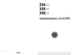
NT-1 T W E E T E R A S S E M B LY
Surface
Mounting
A
D
E
B
D
E
F
C
D
E
F
Recess
Mounting
Recess
Mounting
The tweeters are equipped with wires and attached connectors.
The tweeter wires are designated solid black (-), and black with a white
stripe (+). Locate the corresponding spade connectors from the hardware
pack and crimp them to the end of your chosen speaker wire. Attach the
positive speaker wire lead to the tweeter connector with the black wire with
a white trace. Attach the negative speaker wire to the tweeter connector
with the solid black wire.
6
RETURN TO CONTENTS
N T- 1 T W E E T E R M O U N T I N G
C o n f i g u r i n g t h e N T- 1 Tw e e t e r
Choose the desired method of mounting the tweeters. The N T- 1 tweeters
can be surface or recess mounted while allowing rotation of the tweeter
within the mount for optimal imaging.
Surface Mounting
Locate the disk designated "E" in the tweeter assembly drawing. Once a
mounting location has been chosen, drill a hole into the mounting surface
(first making sure there is space underneath) for the wires from the N T- 1
tweeter using the large hole in the disk as a template. Mount the disk (with
the small spring facing up) to the panel through the two small holes in the
disk using two screws or small nuts and bolts (not supplied).
Locate the surface mount trim ring "A" as shown in the drawing. Place the
tweeter into the ring as shown. Drop the wires from the tweeter through the
large hole in the disk and into the panel. Push down on the trim ring ("A")
until it firmly "snaps" onto the disk ("E"). Rotate the tweeter to the desired
angle.
Recess Mounting
Locate the threaded mounting rings designated "B" or "C" in the drawing.
The choice of "B" or "C" will depend on the thickness of the panel the tweeter
will be mounted through. The "C" mounting ring will accommodate a panel
thickness of up to 3/4 inch.
Locate the disk designated "E" in the drawing. Slip the tweeter wires and
connectors through the disk with the small spring on the disk facing the
bottom of the tweeter. Place the tweeter and the disk through the back of
the threaded mounting ring until the tweeter seats against the inside edge
of the ring. Snap the disk into the groove on the inside of the mounting ring
until it firmly "snaps" into place. Make sure it is fully seated.
Once a mounting location has been chosen, drill a 2-1/8 hole in the panel.
Insert the tweeter assembly into the hole until it seats.
Locate the threaded collar designated "F" in the drawing. While holding the
tweeter assembly onto the panel, thread the collar "F" onto the tweeter
assembly from the back until it is tight.
7
RETURN TO CONTENTS
I N S TA L L AT I O N
M o u n t i n g C o n s i d e r a t i o n s for your Midwoofers
S T U D I O D R I V E R component speakers are designed to mount into most factory
speaker locations with minimum effort. The speaker baskets are designed
to be a universal fit.
When designing your system, a good rule of thumb is to mount the tweeter
close to the midrange/midbass speaker. This usually produces the most
accurate soundstage and image.
Cutting Mounting Holes
Before beginning, now is the time to consider professional installation of
your new components. A mistake now can be costly. If you're set on installing
these components yourself, read on.
Determine a suitable location for the selected components. Make sure the
area under the desired speaker location is free of obstacles such as
computers, wires, fuel tanks, etc. Use a hole saw to make the cut. The
correct hole saw size for the chosen speaker can be found on pages 2
through 5 of this manual.
Passive Crossovers
Choose a location for mounting the crossovers. The F N - 3 and F N - 6
crossovers can be permanently mounted.
Squeeze the sides of the F N - 3 housing and remove the top cover. Locate
the two holes in the base of the crossover.
Temporarily place the base of the F N - 3 or F N - 6 crossover onto the desired
mounting surface and mark the location of the holes.
Drill mounting holes (again making sure there is clearance underneath) in
the desired locations. Mount the crossover using the appropriate screws or
nuts and bolts. Snap the cover back onto the crossover.
8
RETURN TO CONTENTS
I N S TA L L AT I O N
Speaker Wiring
Locate the hardware pack supplied with your new component set. Inside
you will find screws and crimp terminals.
The midrange and midbass speakers are each equipped with a small and a
large terminal. The large terminal is the positive (+) connection and the
small terminal is the negative (-) connection.
Find the corresponding female crimps in the hardware pack. Properly crimp
these connectors to the end of your chosen speaker wire. Attach the speaker
wire to the terminals on the speakers. Mount the speaker into its proper
location.
C o n n e c t i n g W i r e s To T h e C r o s s o v e r
Attach the ends of the speaker wires to the corresponding screw terminals
on the supplied passive crossovers. Refer to the following drawings on pages
10 and 11 to assist in these connections.
Attach the wires from the tweeter to the crossover observing proper polarity.
Note that the crossover has three screws for the tweeter connection. The
extra terminal provides a choice of 2 dB of attenuation. Attenuation of the
tweeter output (reduced level) may be desirable when the tweeters need to
be mounted close to the listening position or when mounted close to glass
or other reflective surfaces. Attach the negative tweeter wire to the screw
terminal labeled (-). Attach the positive tweeter wire to the 0dB screw terminal
for full output, OR to the -2dB terminal for slightly reduced output.
Attach the wires from the midrange speaker to the corresponding screw
terminals on the crossover (FN-6 3 way crossover) if so equipped, again
observing proper polarity. A 2 dB attenuation screw is also provided for the
midrange speaker on the 3 way component sets.
Attach the wires from the midbass speaker to the screw terminals designated
"Woofer" on the crossover again observing speaker polarity.
The two remaining screw terminals on the crossover are the inputs. Attach
the speaker wires from the outputs of your amplifier here observing proper
polarity.
9
RETURN TO CONTENTS
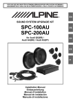
FN-3 CROSSOVER
FN-3
2wayCrossover
INPUT
+
-
WOOFER
+
-
TWEETER
0dB
-2dB
-
Connect to the amplifier
(+) POSITIVE
speaker output
This Terminal
Is Not Used
Connect to the amplifier
(-) NEGATIVE
speaker output
Connect to the Tweeter
(-) NEGATIVE
speaker terminal
Connect to the Tweeter
(+) POSITIVE speaker
terminal [-2dB attenuation]
Connect to the Midrange
(+) POSITIVE
speaker terminal
Connect to the Tweeter
(+) POSITIVE speaker
terminal [no attenuation]
Connect to the Midrange
(-) NEGATIVE
speaker terminal
FN-3 CROSSOVER
Make sure all connections are tight to prevent electrical shorts.
S P E C I F I C AT I O N S
Mounting Length
Mounting Width
Mounting Depth
5.115”
3.335”
1.515”
FREQUENCIES
Tweeter High Pass
Woofer Low Pass
4 kHz
2.2 Hz
10
RETURN TO CONTENTS
FN-6 CROSSOVER
FN-6
Woofer
IN
+
-
-
+
Midrange
-2dB 0 dB
-
-
+
-2dB
Connect to the amplifier
(+) POSITIVE
speaker output
-
Tweeter
0 dB
-
+
Connect to the Tweeter
(+) POSITIVE
speaker terminal
Connect to the amplifier
(-) NEGATIVE
speaker output
Connect to the Tweeter
(-) NEGATIVE speaker
terminal [no attenuation]
Connect to the Tweeter
(-) NEGATIVE speaker
terminal [-2dB attenuation]
Connect to the Midbass
(-) NEGATIVE
speaker terminal
Connect to the Midrange
(+) POSITIVE
speaker terminal
Connect to the Midbass
(+) POSITIVE
speaker terminal
Connect to the Midrange
(-) NEGATIVE speaker
terminal [-2dB attenuation]
Connect to the Midrange
(-) NEGATIVE speaker
terminal [no attenuation]
FN-6 CROSSOVER
Make sure all connections are tight to prevent electrical shorts.
S P E C I F I C AT I O N S
Mounting Length
Mounting Width
Mounting Depth
3.985”
6.325”
1.750”
FREQUENCIES
Tweeter High Pass
Midrange Band Pass
Woofer Low Pass
4 kHz
2.2 kHz - 900 Hz
900 Hz
11
RETURN TO CONTENTS
A D D I T I O N A L I N F O R M AT I O N
Our dealers are trained to achieve the highest level of performance from
our products. If you are installing your new component speakers on your
own and need assistance, please ask your local dealer or call the
S T U D I O D R I V E R Technical Service Department at 1-888-627-6937.
NOTE: Abuse and/or Installation Error: S T U D I O D R I V E R defines abuse as, but not
limited to, burnt voice coils (blackened, no continuity, melted adhesives, coil
separated from the former, etc.), punctured or damaged surrounds, dented cones,
broken speaker terminals, non-S T U D I O D R I V E R modifications, bent, chipped, or
broken frames, ripped spiders, or damaged back plates. Speakers submitted with
any of the above will be considered out of warranty.
The Solution Is Loud And Clear™
Ferrosound means more stable sound quality and performance, smoother frequency response,
reduced distortion, increased power handling, greater efficiency and voice coil centering.
12
RETURN TO CONTENTS
WA R R A N T Y
Three-Year Limited U.S.A. Warranty
This warranty gives you specific legal rights, and you may also have other rights which vary
from state to state. StudioDriver warrants its products to be free from defects in materials
and workmanship under normal use and service for a period of three (3) years from the date
of original purchase when the unit is installed by an Authorized Dealer. Non-Authorized
Dealer installed products carry a one (1) year parts and ninety (90) days labor limited warranty. The extent and conditions of Limited Warranty are as follows:
1. Authorized Dealer Installed Products: StudioDriver will either repair or replace at no charge,
to the original purchaser, any unit which StudioDriver’s examination discloses to be defective and under warranty, provided the defect occurs within three (3) years from the date of
original purchase when the unit is installed by an Authorized Dealer and the product is
returned immediately to StudioDriver. This warranty is not transferable.
2. Non-Authorized Dealer Installed Products: StudioDriver will either repair or replace at no
charge, to the original purchaser, any unit which StudioDriver’s examination discloses to be
defective and under warranty, provided the defect occurs within ninety (90) days from the
date of purchase and the product is returned immediately to StudioDriver. Warranty claims
beyond ninety (90) days for Non-Authorized Dealer Installed Products will be for parts only
and will extend for one (1) year from the date of purchase. This warranty is not transferable.
3. The date of purchase and proof of Authorized Dealer Installation of a StudioDriver product must be established by an original sales receipt which must accompany the article
being returned for warranty work.
4. This warranty shall NOT apply to any StudioDriver product found to have the original
factory serial number removed or defaced. All products received (by StudioDriver) for in
warranty or out of warranty repair, with their original serial numbers removed or defaced,
will NOT be repaired and will be returned to sender, freight collect. Refer to original packaging for the serial number of your component speakers.
5. The provisions of this warranty shall not apply to any StudioDriver product used for a
purpose for which it is not designed, which has been repaired or altered in any way, or
which has been connected, installed, or adjusted other than in accordance with the instructions furnished in StudioDriver’s owner’s manual. Nor shall this warranty apply to any part
which has been subject to misuse, neglect, or accident.
6. StudioDriver does not authorize any other persons to assume any other liability in connection with its products. THIS WARRANTY IS THE ONLY EXPRESS WARRANTY MADE
BY STUDIODRIVER APPLICABLE TO ITS PRODUCTS. ANY IMPLIED WARRANTY OR
MERCHANTABILITY OR FITNESS FOR A PARTICULAR PURPOSE APPLICABLE TO
STUDIODRIVER PRODUCTS IS LIMITED IN DURATION TO THE DURATION OF THIS
LIMITED WARRANTY. STUDIODRIVER SHALL NOT BE LIABLE FOR THE INCIDENTAL,
CONSEQUENTIAL, OR COMMERCIAL DAMAGES RESULTING FROM THE BREACH OF
THIS WRITTEN WARRANTY. Some states or provinces do not allow the exclusion or limitation of incidental or consequential damages or limitations on how long an implied warranty lasts; so the above limitations or exclusions may not apply to you.
7. Your product will be serviced on an in-warranty basis within the warranty period for the
correction of warranted defects. If improper operation of your StudioDriver product should
occur, contact your Authorized Dealer for assistance with the return and factory repair of
your StudioDriver product. If an Authorized Dealer is not available, return the unit including
your name, telephone number, return address, a copy of your sales receipt, and a description of the problem to:
STUDIODRIVER
Service Department
4829 S. 38th Street
Phoenix, AZ 85040-2964
TO RETURN STUDIODRIVER PRODUCTS OUT OF WARRANTY: Return the unit, postage prepaid, in the original protective carton. Please include a description of the problem
and, if desired, a request for an estimate of repair costs. Unless a request for an estimate is
included, the unit will be repaired as necessary. Please contact StudioDriver Customer
Service at 1-888-627-6937 for questions concerning out of warranty repair charges. Repaired unit will be returned with an itemized statement, C.O.D.
RETURN TO CONTENTS