1
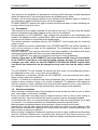
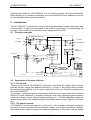
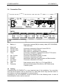
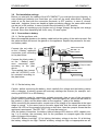
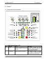
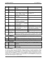
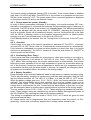
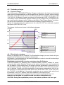
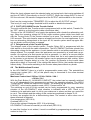
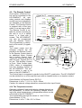
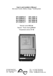
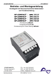
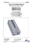
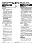
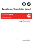
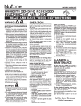
STUDER INNOTEC
HP-COMPACT
User and installer Manual
Sine wave Inverter, Battery charger, Transfersystem
HP-COMPACT
HP-COMPACT
HP-COMPACT
HP-COMPACT
-
HPC 2512
HPC 4024
HPC 5048
HPC 7048
Remote control RCC-01
Remote power sharing RPS-01
Temperature sensor CT-35
STUDER INNOTEC
Rue des Casernes 57
CH -1950 SION
User manual
TEL: ++41 (0)27 205 60 80
FAX: ++41 (0)27 205 60 88
E-MAIL:[email protected]
HP-COMPACT V3.0 E
STUDER INNOTEC
HP-COMPACT
Summary
1
GENERAL INFORMATION...................................................................................................................................3
1.1
1.2
1.3
1.4
1.5
1.6
2
OPERATING INSTRUCTIONS ....................................................................................................................................3
QUALITY AND WARRANTY ....................................................................................................................................3
WARRANTY DISCLAIMER ......................................................................................................................................3
LIABILITY DISCLAIMER .........................................................................................................................................3
PRECAUTIONS ........................................................................................................................................................4
SPECIAL PRECAUTIONS ..........................................................................................................................................4
INTRODUCTION ...................................................................................................................................................5
2.1
2.2
2.3
3
PRINCIPLE SCHEMATIC ...........................................................................................................................................5
DESCRIPTION OF THE MAIN FUNCTIONS .................................................................................................................5
BATTERY CONNECTING ..........................................................................................................................................6
MOUNTING AND INSTALLING............................................................................................................................7
3.1
3.2
3.3
3.4
3.5
3.6
4
INSTALLATION PLACE ............................................................................................................................................7
FIXING ...................................................................................................................................................................8
CONNECTIONS .......................................................................................................................................................8
CONNECTION PLAN................................................................................................................................................9
CABLING ................................................................................................................................................................9
PRE-INSTALLATION SETTINGS ..............................................................................................................................10
CONTROL...........................................................................................................................................................12
4.1
4.2
4.3
4.4
4.5
4.6
4.7
4.8
4.9
4.10
4.11
5
DISPLAY AND CONTROL PARAMETERS .................................................................................................................12
LIGHT EMITTING DIODES (LED)..........................................................................................................................12
PUSH BUTTONS ....................................................................................................................................................13
TURNING KNOBS .................................................................................................................................................13
THE INVERTER .....................................................................................................................................................13
THE BATTERY CHARGER ......................................................................................................................................15
THE TRANSFER SYSTEM .......................................................................................................................................17
THE MULTIFUNCTIONAL CONTACT......................................................................................................................18
THE REMOTE CONTROL .......................................................................................................................................19
THE TEMPERATURE SENSOR ................................................................................................................................19
REMOTE CONTROL FOR POWER SHARING ..............................................................................................................20
PROGRAMMING ................................................................................................................................................20
5.1
5.2
5.3
5.4
5.5
STANDARD SETTING.............................................................................................................................................20
RESET VALUE.......................................................................................................................................................20
BATTERY VOLTAGES AND ABSORPTION TIME .......................................................................................................20
AUXILIARY CONTACT ..........................................................................................................................................21
DISABLING SOME OF THE HP-COMPACT FUNCTIONS ........................................................................................23
6
INSTALLATION MAINTENANCE.......................................................................................................................24
7
EC COMPLIANCE ..............................................................................................................................................24
8
TECHNICAL DATA.............................................................................................................................................25
User manual
HP-COMPACT V3.0 E
2
STUDER INNOTEC
1
HP-COMPACT
General Information
1.1 Operating instructions
This manual is part of the delivery package of every HP-COMPACT inverter-charger. It
serves as guidelines for safe and efficient operation of HP-COMPACT. The instructions
are only valid for use with the following devices and options:
HP-COMPACT : HPC2512 – HPC4024 – HPC5048– HPC7048
Temperature sensor : CT-35
Remote Control : RCC 01
Remote power sharing : RPS-01
Every person who installs a HP-COMPACT and/or works with it must be fully familiar with
the content of this manual and must follow exactly all the warning and safety instructions.
Installation of or any work on the HP-COMPACT must be carried out by a skilled and
trained personnel. Installation and application must comply with the respective local installations codes and safety regulations.
1.2 Quality and Warranty
During production and assembling, all HP-COMPACT appliances go through many controls and tests. Production, controls and tests are carried out in accordance with firm and
established procedures. Every HP-COMPACT has its own serial number, which helps to
refer back to its original data in the event of controls or repairs. That is why you should
never remove the identification plate showing the serial number. The production assembly
and tests on all HP-COMPACT appliances are totally carried out in our company in Sion,
Switzerland. The warranty for these appliances is valid for uses and operating possibilities
mentioned in this manual.
The warranty period for the HP-COMPACT is 2 years.
1.3 Warranty Disclaimer
We do not accept any liability for any damages occurring through use, manipulation, working situation and handling, which are not explicitly mentioned in these operating instructions.
Following cases are not covered by the warranty:
- High voltage at INPUT (i.e. 48V at the Battery INPUT of HP-COMPACT 2512)
- Reverse polarity on Battery connections (+/- reversed)
- Running liquid or oxidation through condensation in the appliance
- Defects caused by force, physical or mechanical means
- Changes not explicitly authorized by STUDER INNOTEC
- Not or only partly tightened screws and nuts after change of fuses or cables connecting
- Transport damage, i.e. through bad handling and /or packing
- Damage from atmospheric overvoltages (lightning)
1.4 Liability Disclaimer
Respecting this manual, servicing and method of installation, functioning, application and
maintenance of the appliance can not be controlled or supervised by STUDER INNOTEC.
Hence we do not accept any liability and responsibility for damages, losses and costs
which result through the use of this appliance or which result through incorrect installation,
incorrect operation or wrong application and maintenance, or which by some other means
maybe connected to each other.
The use of STUDER INNOTEC’s inverters does exclusively involve the user’s liability.
User manual
HP-COMPACT V3.0 E
3
STUDER INNOTEC
HP-COMPACT
This device is not designed for applications involving health care and medical treatments
where the patient life is concerned and where any mishap may be lethal.
Similarly, we do not accept any liability for any violation of the patents rights or violation of
any third party’s rights resulting from the use of this appliance
STUDER INNOTEC reserves the right to modify the technical data or these operating instructions without any prior notice.
1.5 Precautions
This manual must be readily available for the user at any time. The user must be familiar
with the precautions and safety aspects in the country of installation.
During operation of HP-COMPACT, high voltages are generated at the connections and
inside of the appliance which could be lethal. Work on the appliance and on the installation
should only be carried out by skilled and trained people.
The whole installation connected with the HP-COMPACT must comply with the rules and
codes in force.
People without the written authorization from STUDER INNOTEC are strictly forbidden to
carry out any change or repair on the appliances. For authorized changes only original
parts are to be used.
The HP-COMPACT may only be used when it has been installed in accordance with these
instructions and all parts have been correctly assembled and installed.
The HP-COMPACT may only be connected to lead-acid or lead-gel batteries.
Caution: Even when a HP-COMPACT has been disconnected from all connections,
at the OUTPUT point there could still be deadly voltages present. To remove these
voltages you must switch on the HP-COMPACT ON with the ON/OFF switch. After
one minute the electronics are discharged and any work can now be safely carried
out.
The HP-COMPACT is only suitable for internal use and under no circumstances should it
be subjected to snow, rain, or any other wet conditions.
By installations in motorized vehicles the HP-COMPACT must be protected from waterspray and any other wet conditions.
Caution: In normal use lead-acid and lead-gel batteries give out explosive gases. Never
smoke or allow a spark or flame in the vicinity of batteries. The batteries must always be
stored or placed in a well ventilated room, they should be placed in such a way that there
is no danger of short-circuit through carelessness. Never charge frozen batteries.
1.6 Special precautions
While working on batteries there should always be a second person close to you or within
your voice range, in case help is needed.
Plenty of fresh water and soap must be ready at hand so that in case of acid coming in
contact with skin, eyes and clothes, the areas in question can be thoroughly washed.
If acid enters the eyes, you must thoroughly wash them with cold running water for at least
15 minutes. It is recommended that you immediately consult a medical doctor.
Baking powder neutralizes battery acid electrolyte. Always keep some at hand.
Special care must be taken when working with metal tools near or on the batteries. With
tools such as screwdrivers, spanners etc. short-circuits can result. Sparks produced by the
short-circuit can cause an explosion.
When working on batteries all personal metal items such as rings, necklaces and bracelets
must be removed. Batteries are so powerful that short-circuit with these items can melt
them and thus cause severe burns. Always follow the battery manufacturer instructions.
User manual
HP-COMPACT V3.0 E
4
STUDER INNOTEC
HP-COMPACT
Under certain conditions HP-COMPACT or a connected generator can start automatically.
While working on an electrical installation you must ensure that these appliances are disconnected beforehand from the installation.
2 Introduction
The HP-COMPACT is a sine wave inverter with integrated battery charger with many additional functions, it has been developed to be used as stand-alone (no grid-feeding) AC
provider, or as continuous / break-free current supply provider (UPS).
2.1
Principle schematic
Circuit breaker (thermal)
AC IN
AC Input
L
PE
L
100nF
2,2nF
2,2nF
2,2nF
2,2nF
N
AC OUT
PE AC Output
N
AUX.
CONTACT
Filter
4x2,7MΩ
Temp. sensor
CT35
BATTERY
Inverter/
charger
Fuse
1uF
Equalize
Transfer delay
1uF
RCC-01
COM P A CT
RC C-01
AC OUT
A
%
160
Program
RESET
ALARM
(Select)
Over Temp.
70
100
60
80
50
60
40
40
30
20
Overload
20
10
Battery
Low/High
10
5
Inv erter
EQUALIZE
Contact active
Contact manual
AUXI LIARY CONTACT
(Program)
130
INVERTER
Charger
Microprocessor
controlled
Display
INVERTER - CHARGER
TR AN SFE R
AC IN
CHARGER
SOLAR CHARGE
OFF
ON/OFF
(Change status)
RPS-01
CT35
Max. 6m
2.2
Temp. / remote
power sharing
6p
8p
.
RCC-01
Remote control
Max. 40m
Description of the main functions
2.2.1 The inverter
The sine wave inverter HP-COMPACT generates a sinusoidal AC voltage with an exceptionnlaly precise voltage and stabilized frequency. In order to start large electric motors,
the user has the possibility to use a short surge power which is 3 times the nominal power
of the HP-COMPACT.
The inverter is protected against overload and short-circuit. A power stage with the latest
MOS-FET power transistors, a toroidal transformer, and a fast regulating system makes a
robust and reliable inverter with the highest efficiency. A 1-20 Watt adjustable charge detection system allows the smallest energy consumption and ensures a long life for the battery.
2.2.2 The transfer system
HP-COMPACT can be connected to an AC source. For example a stand-by emergency
generator or the AC network. With the transfer system, on one side you have an alternatiing voltage at the output for the use of consumer appliances. On the other side the battery
User manual
HP-COMPACT V3.0 E
5
STUDER INNOTEC
HP-COMPACT
park is being charged. The distribution of energy between the consumer appliances and
battery charger is automatic.
2.2.3 The battery charger
The built-in battery charger is so designed that it can charge the battery quickly and fully. A
microprocessor controlled, Step charging process, ensures the optimal charging of the
battery. The desired charging current can be set continuously from 0 to 70/90/100/110 A,
as per the model. The setting is made accordingly to the battery capacity and power available.
The battery charger is designed for lead-acid and lead-gel batteries. Thanks to the floating
charge system the batteries can remain continuously connected.
2.2.4 Remote control
As an option, a remote control RCC-01 can be connected to HP-COMPACT. All operating
features and displays, save the adjustment levels (22/23/24/26), are available on the remote control. It is supplied with a 20m long cable. This cable can be up to 40m long. On
the remote control, output power and charging current are also displaid.
2.2.5 Remote control for Power Sharing
This remote control RPS-01 can be connected to the HP-COMPACT in the gland for the
temperature sensor. The maximum current available from the energy source can be adjusted by the turning button.
2.3 Battery connecting
Lead-acid batteries are normally available in blocks of 2V, 6V or 12V. In most cases, to
generate the necessary operating voltage and the capacity of the batteries for the HPCOMPACT many batteries have to be connected together in parallel and or in series. Here
are 3 examples of connection:
2.3.1 Connection in parallel
12V
User manual
12V
12V
HP-COMPACT V3.0 E
P
H
C
1
5
-2
6
2
STUDER INNOTEC
2.3.2
2V
HP-COMPACT
Connection in serie
2V
2V
2V
2V
2V
H
2V
2V
2V
2V
12V
2V
2V
12V
2V
2V
2V
2V
12V
P
C
1
5
2
-
2
2V
2V
H
P
12V
H
P
C
2
0
-4
4
0
5
C-
4
8
2.3.3 Connection in parallel and in serie
12V
12V
12V
12V
H
P
2
0
4
C-
4
3 Mounting and installing
3.1
Installation place
The location of the HP-COMPACT must be driven by the following criteria:
- Protection from unauthorized handling
- Dry dust free room, no condensation
- Never install directly over the battery and never in a cabinet together with the batteries
- Keep ventilation holes free
- In mobile installations it is important to keep the vibrations down as low as possible
User manual
HP-COMPACT V3.0 E
7
STUDER INNOTEC
3.2
HP-COMPACT
Fixing
3.2.1 HP-COMPACT
Basically the HP-COMPACT can be installed in any desired location but only vertically.
First of all the plate supplied along with the HP-COMPACT must be screwed firmly (due to
the weight of the device) on the wall. Then the HP-COMPACT is hooked on the plate and
screwed underneath.
Cautious: the fixing must be fully made otherwise the HP-COMPACT may fall and cause
important damages.
In motor vehicles HP-COMPACT must be fixed on vibrations reducing elements. The HPCOMPACT must not be fixed on a combustible base, as the back of the casing can get hot
and reach up to 60 degrees Celsius.
3.3
Connections
3.3.1 General instructions on connecting
The cable connection on the terminals AC INPUT and AC OUTPUT must be carried out
with a screwdriver Nr.3 and the connection of the AUX RELAY terminal with a screwdriver
Nr.2.
The conductor cross section on the terminals AC INPUT / AC OUTPUT / must comply with
the local rules.
All connecting cables and also the battery cables must be fixed with strain relief clamps.
The fuses supplied with the HPC4024, 5048 and 7048 have to be installed (see description in 3.4). The cable cross section for the HP 2512, 4024, 5048 and 7048 is resp. 95, 70,
50 and 70 mm2 and their length must be as short as possible (max. 2m).
The fuse supplied with the product (save for HPC 2512) does not protect the battery cables.
To protect the battery cables, a fuse corresponding to the conductor cross section must be
fixed directly on to the battery.
All cables must be tightly screwed in place. For safety, a yearly control is recommended. In
mobile installations controls must be carried out more often.
Connecting must be done by qualified people. Material such as cable, connectors and distribution boxes, fuses etc. used in the installation must comply with the respective valid
low-voltage installation rules and regulations in force.
3.3.2 Protection cover of the terminals connections
The protection cover must to be closed after any service on the appliance.
User manual
HP-COMPACT V3.0 E
8
STUDER INNOTEC
HP-COMPACT
3.4 Connection Plan
N
Remote
control
RCT-01 D
L
B
H
G
K
A
C
E
L
F
Battery
temperature sensor CT35
AC in
L
N
Auxiliary
contact
N
AC out
remote power sharing RPS-01
M
J
A
Battery +/-
B
C
D
E
F
Reserved
Remote contr.
Transfer delay
Equalize
Temp.
G
H
J
K
L
M
N
Aux. Contact
AC Input
ID Plate
AC Output
Reserved
Hole
Protection
3.5
Cabling
Connection terminal (M8) for battery cable (HPC 4024/5048/
7048 with fuse)
Connection terminal for Remote Control RCC-01
Slide switch for Transfer Delay
Slide switch for equalization of the Battery
Connection terminal for Temperature sensor CT-35 and/or
Remote Power Sharing RPS-01
Connection terminal for Auxiliary Contact
Connection terminal for AC-input
Identification plate with Technical data and Serial number
Connection terminal for AC-output
Pass through hole for RCC-01, CT-35 and RPS-01
Thermal circuit breaker 30A (50A for HPC7048) for the
Transfer system
Connecting the HP-COMPACT is a very important step of the installation. You must take
care that all connection work is carried out in a clean and correct way and that under no
circumstance a cable is connected to a wrong terminal.
Connecting of the HP-COMPACT must be carried out in the following order. In case of
dismantling this order must be reversed.
User manual
HP-COMPACT V3.0 E
9
STUDER INNOTEC
HP-COMPACT
3.6 Pre-installation settings
Before you start with the cabling of the HP-COMPACT you must set the type of battery. In
case sealed-gel batteries are used then you must set the small slide-switch „Equalize“
which is on the front with the connection terminals, in OFF position. In case of „normal“
lead-acid – batteries, these can handle a higher equalizing charge, the same slide switch
can be set in ON position. In case of doubt leave the setting in OFF position.
This will allow an equalizing cycle (higher end of charge voltage) during the next charge
process. Since then equalizing will occur every 25 usual cycles.
3.6.1 Connection to battery
3.6.1.1 On the appliance side
Mount the supplied glands on the battery cable before the setting of the cable terminal. Set
the cable terminal and mount the glands on the appliance. Repeat the process for the second battery cable.
Cable terminal M8
Bolt M8 x 16
Steel washer
Connect the red cable (+)
on the “+ Battery” appliance
connection point according
to the plan below.
Connect the black cable (-)
on the “- Battery” appliance connection point
according to the plan
above.
The supplied fuse (except
with the HPC2512) must
be mounted according to
the plan below.
Lugs M10
Screw M8x30 Torque 10Nm
Steel washer
Ceramic washer
Fuse CF8
3.6.1.2 On the battery side
Caution: before connecting the battery, check carefully the voltage and the battery polarity
with a voltmeter. A polarity reverse will seriously damage the inverter (for example: connecting a HPC2512 to a 48V-Battery).
Get the batteries ready for connection: suitable terminals, fuse on one of the connection
points, cable in good shape with, if necessary, terminals rightly set. Mount the red cable on
the positive (+) pole, and the black cable on the negative (-) pole of the battery.
While connecting the second cable, a spark due to the charge of the capacities at the input
stage is normal. In the same time an acoustic signal tells that the control processor has
started. All LED’s of the synoptic light during a short time, then the synoptic shows that the
appliance has stopped. The LED “OFF” (13) must be turned on.
After the battery connection, the battery state-of-charge LED shows a 100% capacity during 1 to 2 minutes, the necessary time for the processor to compute again the current
state-of-charge of the battery.
If the LED “Battery Low/High” (12) is lighting, the battery voltage is too low. If it is blinking,
the battery voltage is too high. Caution: a battery voltage too high or inappropriate can seUser manual
HP-COMPACT V3.0 E
10
STUDER INNOTEC
HP-COMPACT
riously damage the HP-COMPACT. For instance the connection of a 24 V battery with the
HP-COMPACT 2512.
If by mistake the HP-COMPACT has been wrongly been connected (reverse battery polarity) it is likely that the internal protection fuse has melted and has to be replaced. In that
case it is necessary to disconnect all connections to the HP-COMPACT, including the battery. If after the fuse replacement and after re-connection of the battery with the right polarity, the HP-COMPACT remains out of order, it must be brought back to your merchant for
service.
3.6.2 Connection to the 230Vac-consumer appliances (AC OUTPUT)
The 230V consumer appliances must be connected to the terminals AC OUTPUT with cables which cross section has to follow the local rules in force (usually 2,5mm2). Connections are marked as follows “N“ Neutral, “PE“ Earth (connected to the appliance box), “L“
Live.
Caution: High voltages can be there. Make sure that the HP-COMPACT is turned off (LED
13 lighting) before the connection.
3.6.3 Connection to the 230Vac Input (AC INPUT)
The 230V-supply from network or from a generator must be connected to the input terminals AC INPUT with cables which cross section depends on the power source (usually
2,5mm2). Connections are marked as follows: “N“ Neutral, “PE“ Earth, “L“ Live (connected
to the appliance case).
3.6.4 Connection to Auxiliary Contact
This contact is a potential free change over contact The currents and voltages allowed for
this contact are max. 16A/250Vac. The LED 5 “Contact active” shows the position of them:
alight mind active and off mind non-active. The schematic view of the connections on the
front, show the relay in the non-active mode.
3.6.5 Connection to Remote control
The Remote Control RCC-01 is connected in the terminal marked „Remote control“ with a
20m long cable and a RJ11/8 connector. The Remote Control can be plugged IN or
plugged OUT during any operation situation. Push in the connector softly until you hear the
„click“ showing that the connector is locked. The same applies to the plug in the Remote
Control.
The length of the cable for Remote Control should not exceed 40m. We deliver it with 20m
cable.
3.6.6 Connection to Temperature Sensor (Temp.)
The temperature sensor CT-35 is connected in the terminal marked „Temp“ with a 3m long
cable and a RJ11/6 connector. The temperature sensor can be plugged IN or plugged
OUT during any operating situation. Push in the connector softly until you hear the „click“
showing that the connector is locked. The temperature sensor must be glued to the wall of
the battery or near it. The Temperature Sensor cable must not be tied together with the
battery cables or laid in a rope/bundle.
3.6.7 Connection to the Remote Control for the „Power Sharing“ (RPS-01)
This remote control is connected with a 20m long cable and a RJ11/6 connector in the
connection terminal „F“ (Temp. sensor). It can be connected and disconnected at any time.
Push in the connector softly until you hear the „click“ showing that the connector is locked.
In case the remote control is connected together with the Temp. sensor, a short cable with
a Y-connector will be connected in the terminal „F“ (can be supply as an option).
User manual
HP-COMPACT V3.0 E
11
STUDER INNOTEC
HP-COMPACT
4 Control
4.1
Display and control parameters
POWER MONITOR
Charge current Inverter output
[A]
[%]
>100
200
90
160
80
130
70
100
60
80
50
60
40
40
30
20
20
10 25
10
5
Charger - Inverter
INPUT LIMIT
CHARGER
30A
0
0
22
STANDBY
230V
100A
26
AC IN
TRANSFER
150V
23
20W
OFF
24
8
1
AC OUT
7
CHARGER
2
9
14
EQUALIZE
Program
4
Contact active
5
Contact manual
6
AUX. CONTACT
(Program)
21
15
16
INVERTER
20
RESET ALARM
(select)
10
Over Temp
11
12
Overload
13
OFF
19
ON/OFF
(Change status)
17
18
Batt Low/High
4.2 Light Emitting Diodes (LED)
LED
1
Marking
AC IN
LED lit
Voltage corresponding to selfadjusted values is at the AC
IN input.
2
CHARGER
Battery charger is working
User manual
HP-COMPACT V3.0 E
LED blinks
A voltage outside the selfadjusted values is at the AC IN
input, or the HP-COMPACT is in
synchronization phases
The battery charger is locked
OFF (see chap. 4.6) or provisory
out of order. In that last case it
will restart within 10 seconds
12
STUDER INNOTEC
3
4
HP-COMPACT
Reserved
Program
9
Program mode for Aux.
Contact
Contact active Auxiliary Contact is activated
Contact man- Aux. Cont. manually activated
ual
TRANSFER
Transfersystem is active. Incoming voltage is being sent
directly to AC OUT outlet
AC OUT
There is a voltage at the AC
OUT outlet
INVERTER
Inverter is working
10
Over Temp.
5
6
7
8
11
12
13
14
15–18
For the time being the HPCOMPACT is out of service
because of overheating.
Overload
The HP-COMPACT is out of
service because of overload
or short-circuit
Batt. Low/High Battery voltage is too low
OFF
HP-COMPACT is turned off.
Turning it back on is only possible manually.
EQUALIZE
Battery equalizing is set
State of charge of the battery
25
POWER
MONITOR
4.3
19
Push buttons
ON/OFF
20
21
RESET
Aux. Contact
4.4
22
23
Turning Knobs
CHARGER
TRANSFER
24
26
STANDBY
INPUT LIMIT
4.5
Transfer (bypass) is disabled
(see chap. 4.7)
The Inverter is in Standby-Mode
Forced Inverter Mode (see chap.
4.5)
Battery voltage is or was to high
HP-COMPACT is for the time
being turned off. Turning it back
on will follow automatically !
LED 15 – Absorption time is running
Display the value of the output power in % of Pnom (in Inverter
Mode) and the charge current in Amps (in Charger Mode). In this
mode the red LED indicates that power sharing is in use (>100A).
Turning the HP-COMPACT on and off (Help Button for Programming)
Alarm Signal off (Help Button for Programming)
Control Aux. contact (Help Button for Programming)
Adjustment for max. Charging Current
Adjustment for Transfer Voltage Threshold (TRANSFER – INVERTER)
Adjustment for „Standby“ system
Must be adjusted to the maximal available current of your AC
INPUT supply
The Inverter
An Inverter is built in the HP-COMPACT, which generates a sinusoidal alternating voltage
of a very high quality. With this Inverter any 230Vac alternating voltage appliance up to the
nominal power of your HP-COMPACT can be operated. Thanks to the generous dimensioning of the HP-COMPACT, you can operate appliances requiring higher power than the
nominal power of the HP-COMPACT for a short time. The HP-COMPACT provides up to
3-times the nominal power to start motors.
User manual
HP-COMPACT V3.0 E
13
STUDER INNOTEC
HP-COMPACT
The Inverter mode is displayed through LED 9 (Inverter). If the Inverter Mode is disabled
(see chap. 5.5) LED 9 will blink. If the LED 9 is lit, the Inverter is in operation and you have
230Vac at the output AC OUT. The actual power of the connected appliance is displayed
on the power monitor 25 and on the Remote Control.
4.5.1 Charge detection system „Standby“
In order to avoid unnecessary discharge of the battery, the inverter switches OFF automatically if no appliance is connected and switches ON automatically again if appliance is
connected. The LED 8 blinks if the inverter is in Standby-Mode. The switching-on/starting
level can be adjusted with the turning knob 24 „STANDBY”. Adjusting the switching-on
level is as follows: Switch off all consuming devices, turn the Turning Knob 24 to the right
until the LED 8 is blinking, switch on the smallest consuming device (i.e. Mobile phone
charger), turn the Turning Knob slowly to the left until LED 8 is lit.
If the Standby-Mode is not wanted, turn the Turning Knob 24 to the left, to the OFF position.
4.5.2 Overload
If the Inverter is too long or too heavily overloaded, it switches off. The LED 11 „Overload“
is lit and LED 13 „OFF“ blinks. After ca. 10 seconds the Inverter switches on automatically.
If the Inverter is overloaded four times one after another in a short time, then it no longer
switches on automatically. The LED 13 remains lit. Press the push button 19 „ON/OFF“ in
order to switch on the Inverter.
4.5.3 Overheating (Over Temp.)
If the Inverter has been overloaded for a long time or it has been working in too high surrounding temperatures, it will switch off. The LED 10 „Over Temp.“ is lit and the LED 13
„OFF“ blinks. After cooling down, the inverter switches back on automatically. One minute
before the inverter switches off for too high temperature it gives out an acoustic alarm signal. If the Auxiliary Contact has been programmed to detect the high temperature then it
synchronizes the relay with the alarm signal. In this way, for example, an emergency backup system can be started without any break in the energy supply.
4.5.4 Battery Condition
Deep discharge of the lead-acid batteries leads to high losses in capacity and early aging.
That is why the battery condition is continuously controlled and supervised. With low voltage the inverter switches off. The LED 12 „L/H Batt.“ is lit and the LED 13 „OFF“ blinks.
When the battery voltage gets up to 12.1V / 24.2V / 48.4V, the Inverter switches on automatically. One minute before the Inverter switches off due to low voltage it gives out an
acoustic alarm signal. If the Auxiliary Contact has been programmed to detect the low
voltage then it synchronizes the Aux. Contact with the alarm signal. In this way, for example, an emergency back up system can be started without any break in the energy supply.
The low voltage is set to 11.8V / 23.6V / 47.2V. These settings are standard for most batteries. These voltage levels are maintained by the built-in Battery-Management-System of
the HP-COMPACT by matching the load and the battery condition.
This setting is comparable with the levels of 10.8V/ 21.6V / 43.2 which are given for most
batteries at nominal load.
All voltage levels can be programmed. See the instructions under the section on Programming. Check with your battery supplier which voltage values should be set.
User manual
HP-COMPACT V3.0 E
14
STUDER INNOTEC
HP-COMPACT
4.6 The battery charger
4.6.1 Cycle of charge
The full automatic HP-COMPACT Battery Charger is adjusted at the factory so that most
lead-acid and lead-gel batteries can be charged to the maximum. As soon as the minimum
alternating voltage for the AC IN set on the Turning Knob 23 is available at the input (LED
1 AC IN is lit), the Battery Charger is switched on automatically (LED 2 CHARGER is lit).
The battery is fully automatically charged matching to the charge level, the adjusted voltage levels and the charge current. Thanks to the built-in Float Charge System, the batteries can be left connected for unlimited time with the Battery Charger switched on.
During the charging phase the appliances at the outlet AC OUT are continually supplied
with power (LED 8 AC OUT is lit).
The charger functions are shown in the following diagram:
[V/cell]
[A]
2.50
Equalizing V
Absorption V
90
2.33
Floating V
Charge A
2.17
60
2.00
30
A Charge time with set current
A
t
B
C
D
B Equalizing time
C Absorption time
D Floating time
4.6.2 Equalization charging
Before you program the HP-COMPACT for Equalization-charge you must check with your
supplier that the batteries are suitable for this process.
Equalization is recommended for the lead-acid batteries in order to mix well the electrolyte
fluid and to clean the lead plates.
Equalization mode should never be used when using Gel-Batteries
If the HP-COMPACT is operating with a lead-acid battery, which is suitable for equalization, the slide switch „Equalize“ which is on the cable connection side, must be placed in
the ON position. In this setting, every 25 charge cycles an equalization is carried out for 20
minutes (factory setting). During such a charge cycle the LED 14 is lit and during equalizing it is blinking. Charge cycle with equalization can be started independently from the actual program. For this purpose the slide switch must be slid from “OFF” to the “ON” position. The LED 14 will light up. If the periodic equalization is not required, slide switch must
be slid back to the „OFF“ position after the completion of the manual cycle.
The equalizing voltage can be changed. How to proceed is explained in chap. 5.3.
Batteries not designed for equalize should never been charged this way.
CAUTION: During the equalization process, the batteries produce a lot more gas.
User manual
HP-COMPACT V3.0 E
15
STUDER INNOTEC
HP-COMPACT
DANGER OF AN EXPLOSION !! The battery room must be well ventilated.
4.6.3 Input current repartition (Power sharing)
To manage the power available on the AC INPUT (depends on the supply use) the HPCOMPACT is equipped with a system usually called “Power sharing” or INPUT power distribution. With this function it is possible to limit the AC INPUT current assigned to the
charger. The more current it uses on the OUTPUT the less it gives to the charger. Priority
to the OUTPUT. When the power sharing is used the LED 200% (red) is lit to point out that
the charge is limited.
Caution: if the power use on the OUTPUT is higher than the value of the INPUT LIMIT (26)
the HP-COMPACT cannot limit the current, then the generator means to stop or the circuit
breaker means to break before.
4.6.3.1 Set the INPUT LIMIT (26)
The current available for the HP-COMPACT depends on the
Generator
Current
supply used from a motor generator, the network of a camppower
(230V)
ing or of a shore connection. The value of the turning knobs
500W
2A
INPUT LIMIT (26) must be adjusted lower or equal to the cur900W
4A
rent available from the source.
1500W
6.5A
For example if you have a generator of 2kW you must adjust
2000W
8.5A
the turning knobs 26 to a max. 8.5A. To calculate this, one
3000W
13A
divides the nominal power (2000W) by the voltage (230V). If
5000W
21A
you have a circuit breaker (i.e. 6A) before the HP-COMPACT,
then you set this value on the turning knobs (26) (i.e. 6A).
This adjustment can be done remotely with the optional RPS-01 (see section 3.6.7). In that
case the smallest values will be taken into account.
4.6.4 Charging current
The maximum charging current for the battery can be adjusted with the Turning Knob 22
(CHARGER). The charging current of the battery should be set to approximately 10 – 20%
of the battery capacity (at C10). This means that the charging current for a battery with
300Ah should be set between 30 – 60A.
The charging current is displayed on POWER MONITOR (25) of the front panel or on the
Remote Control.
4.6.5 Battery Condition
Built-in microprocessor with a specially developed algorithm calculates the actual state of
charge of the battery and displays it on LED 15 – 18. The LED 14 is lit when the system is
carrying out a charge cycle with equalization.
Notice: the exact measure of the battery state of charge with electrical parameters is almost impossible. The display of the state of charge is always more or less precise. The
measure system built in the HP-COMPACT takes into account the battery voltage, the discharge and charge current as well as the undulation of the voltage. If the battery and the
HP-COMPACT are used according to their technical data, the battery state of charge is
displaid accurately. In the following cases of use the display can diverge:
User manual
HP-COMPACT V3.0 E
16
STUDER INNOTEC
-
HP-COMPACT
Battery charge or discharge with too
14
high currents
Battery cable cross section too small
Battery connections badly tightened or 15
corroded
Charge of the battery with external bat- 16
tery charger
Discharge of the battery with users not 17
connected to the HP-COMPACT
Work with defectuous or sulphated bat- 18
teries
Equalizing cycle
Battery 75 – 100%
Battery 50 – 75%
Battery 25 – 50%
Battery 0 – 25%
This means that the display can, within few minutes during the charge, commute from 25%
to 75% or during the discharge, to the opposite direction.
As many of the working cases mentioned above often occur, the measure system of the
HP-COMPACT takes into account, during the charge, only the peaks of the voltage undulation. As a consequence, the battery voltage at the start of the absorption stage, measured by a voltmeter will appear deeper. By decrease of the charge current the voltage will
reach the exact values.
For safety reasons, you must get the recommended charge voltage and charge currents
from your battery supplier. The voltage levels and charge characteristics can be changed
through Programming. The instruction for programming of battery charger is in the section
„Programming“ (Chap. 5.3). The correct charging is mandatory for a safe function and a
long-life of the battery.
4.7
The Transfer system
When an AC voltage is at the input AC IN of the HP-COMPACT, the LED 1 AC IN is lit.
When this voltage matches the lowest adjusted value set by the Turning Knob 23 TRANSFER, and the frequency is between 44Hz and 65Hz, this voltage is switched directly to the
battery charger and to the output AC OUT. The LED 7 TRANSFER is lit. The inverter is
switched off and the battery charger switched on. This process is automatic, unless the
charger mode or the transfer mode is disabled (see Chap. 5.5).
The maximum current of the Transfer switch is 30A (50A for HPC-7048). That means
through this system, appliances up to a maximum of al 6900 Watt at 230V(11500W for
HPC7048) can be operated. When the Battery Charger is working, part of this power is
used for charging according to the power sharing system.
The Transfer system is protected against overload with a circuit breaker on the AC Input
side of the HP-COMPACT. If the system has been overloaded, the button/pin of the fuse
will pop out. To put the automatic safety system back in to operating you must push this
pin back.
Note: in the Inverter operation, The HP-COMPACT generates a true sinusoidal and quartz
stabilized output voltage. However if the HP-COMPACT is supplied from a grid or a generator and the transfer contact is active, then you have at the output AC OUT the same
voltage as that at the input. This voltage can not be modified by the HP-COMPACT !
4.7.1 Set the transfer voltage threshold
The voltage threshold of the transfer can be adjusted between 150 to 230V with the turning knobs (23). From factory this value is 200V. Most appliances can work on this voltage.
User manual
HP-COMPACT V3.0 E
17
STUDER INNOTEC
HP-COMPACT
When the Input voltages reach the selected value on turning knob, the inverter switches off
and the AC INPUT goes directly on the AC OUTPUT. When the voltage INPUT is less of
20V the value set, the transfer is stopped and the OUTPUT switches back on the inverter.
Don’t use the turning knobs “TRANSFER” (23) to adjust the AC OUTPUT voltage !
This is only it’s only a voltage threshold level to enable or disable the transfer.
4.7.2 FAST (UPS)- MODE for the Transfer Switch
The quick and break free Transfer mode is programmed with a slide switch „Transfer Delay“ OFF, which is on the front side (cable connections side).
The aim of the HP-COMPACT is to supply the appliance with a break-free alternating voltage. When the incoming voltage AC IN no longer matches values which have been set
with the Turning Knob 23, the Inverter switches on at once. The transfer is carried out in
0.02 seconds. This quick transfer ensures a break-free function for most appliances. If you
have an alternating voltage back at the input AC IN, transfer system starts up again without any break, and the inverter is stopped.
4.7.3 Delayed mode of the Transfer System
The delayed mode of the transfer system „Transfer Delay ON“ is programmed with the
slide switch on front with the cable connections. The HP-COMPACT provides a break-free
alternating voltage for the appliance. A quick transfer switch is not always sensitive nor is it
always desired. For example, when the appliances are operated by a small back-up generator. An overload of a short period on such a generator, i.e. start of a vacuum cleaner
etc., has the effect of decreasing the voltage for a short time. As in such cases the transfer
to the Inverter is not desired, the transfer system can be programmed with a delay. When
the slide switch (Transfer delay) is in the „On“ position, the transfer to the inverter takes
place with a delay of 5 seconds. If the voltage falls below 100Vac, the transfer takes place
without delay ! The transfer switching to the Inverter takes place without any break.
4.8
The Multifunctional Contact
In the HP-COMPACT there is a built-in programmable power relay. The potential-free
change-over contact (NO – NC) of this power relay is connected to the screw terminal
AUX CONTACT.
Maximum Contact load: 230Vac / 12Vdc / 24Vdc / 16A !
> 36Vdc / 3A !
With the Push Button 21 „AUXILIARY CONTACT“ the contact can be manually switched
on or off independently from programming and from the operating situation. The LED 5
“Contact active” shows the status of the contact. The drawing up the screw terminal “AUX
CONTACT” is the inactive position mode, LED 5 “Contact active” off.
The switching on and off of this contact can be freely programmed for every operating
situation of the HP-COMPACT witch situation is indicated with a LED. There is no
limitation to its application and it is left to your wishes as to where and how you would like
to use it. The example and the setting of this contact are explained in chapter 5.4.2.
In factory we program this for a disfunctioning alarm. The contact is active when one of
these situations is detected:
Over temperature (LED 10 lit)
Overload (LED 11 lit)
Over or less voltage of batteries (LED 12 lit or blinking)
HP-COMPACT is turned off manually or with a fault (LED 13 lit)
In case this function is not wished, it must be modified by programming according to procedure in chap. 5.4.
User manual
HP-COMPACT V3.0 E
18
STUDER INNOTEC
HP-COMPACT
4.9 The Remote Control
Remote control
As an option, a Remote ConCO M P A CT INVERTER - CHARGER
trol can be connected to the
RCC-01
TRANSFER
A
%
HP-COMPACT. All ope160
AC IN
AC OUT 100
rating controls and displays
90
160
130
except from level adjustment
80
CHARGER
INVERTER
70
100
are available on the Remote
RESET
60
80
SOLAR CHARGE
ALARM
Control. The Remote Control
(Select)
50
60
is supplied with a 20m long
40
40
Over Temp.
EQUALIZE
30
20
cable. It can as long as 40m.
Overload
20
10
Program
The Remote Control is suiBattery
10
5
Ch Inv
Low/High
Contact
active
table for surface mounting on
arg ert
er
er
the wall or on to a switch
OFF
Contact manual
board. It is fixed with 4
ON/OFF
AUXILIARY CONTACT
screws. The HP-COMPACT
(Program)
(Change status)
can also be programmed
with the Remote Control.
The Programming is descrybed in the section „Programming“.
The output power and the
charging currents are displayed on the Remote Control.
In the Remote Control there is
ON/OFF
an additional Alarm Contact
! -batt !
and a built-in Control Input.
These two functions are avai1234
lable through Tip-jack RJ11/4
COMPACT
for use. This Auxiliary Contact
60V/0,5A
Remote control
max.
is Front / Work Contact (max.
Dry contact
0.5A!), which is independent
only
from the Auxiliary Contact of
the HP-COMPACT. This contact is active in case of an
alarm of the HP-COMPACT.
The Control Input is connected in parallel to the ON/OFF- push button. The HP-COMPACT
can be switched on or off through this input with an impulse button or an impulse contact.
Order Number for Remote Control: RCC-01
Dimensions: H x B x T / 111.5 x 136.5 x 25mm
Caution: No external voltage should be connected to this Input Control.
4.10 The Temperature sensor
Operating voltage of lead-acid batteries change depends on
the temperature. To correct the operating voltages according to the actual temperatures, a temperature sensor can be
connected to the HP-COMPACT.
The compensation through the sensor is –3mV/°C/Cell.
Order Number: CT-35
Dimensions: H x B x T / 58 x 51.5 x 22mm
User manual
HP-COMPACT V3.0 E
19
STUDER INNOTEC
HP-COMPACT
4.11 Remote control for „Power Sharing“
If the Remote control RPS-01 is installed, the Trimmer (26) “INPUT LIMIT“ has to be set
on the value max.. The HP-COMPACT takes into account the lowest values set on the
inverter and on the Remote control.
The current available at the HP-COMPACT input will be determined by the power of the connected source (generator,
grid etc...). The potentiometer on the RPS-01 must be adjusted lower or equal to max. value of the power source.
For instance if the source is a generator of 2000 Watt, the
potentiometer has to be set at max. 8A. This value is obtained in dividing 2000 Watt by 230V. If the HP-COMPACT
is connected to a power source which is protected by a 6A
circuit breaker, the potentiometer must be set at a max.
value of 6A.
Caution: the HP-COMPACT will not limit if an appliance draws more current than
available from the source ! This means that the connected generator will be overloaded or that the circuit-breaker before the HP-COMPACT will break.
5 Programming
5.1 Standard setting
The HP-COMPACT is delivered with the following default setting:
5.1.1 Battery voltage
Low voltage
Float Charge
End of Charge Voltage
Equalization
Absorption Time:
11.6V / 23.2V / 46.4V
13.5V / 27.0V / 54.0V
14.4V / 28.8V / 57.6V
15.3V / 30.6V / 61.2V
2 Hours
5.1.2 Auxiliary contact
Active in case of defect or manual turn off with the LED 10/11/12/13.
5.2 Reset value
When the HP-COMPACT is to be connected to a battery or after an interruption (RESET),
it is always programmed with these standard settings (see above).
In order to get to these settings during operation you must press the three Push Buttons
19/20/21 simultaneously for a minimum of 2 seconds.
5.3 Battery voltages and absorption time
The voltage levels (low voltage, float charge, end of charge and equalization) and the duration of the absorption charge can be changed.
The display of these voltages and the times in the program mode are in accordance with
the diagram shown below:
5.3.1 Table of voltage and timing threshold
User manual
HP-COMPACT V3.0 E
20
STUDER INNOTEC
Low voltage
LED 13
HP-COMPACT
Float Charge
LED 12
Absorption
LED 11
Equalization
LED 10
LED 12V 24V 48V 12V 24V 48V 12V 24V 48V
14
12.0 24.0 48.0 13.7 27.4 54.8 16.2 32.4 64.8
15
11.8 23.6 47.2 13.6 27.2 54.4 15.6 31.2 62.4
16
11.6 23.2 46.4 13.5 27.0 54.0 15 30 60
17
11.4 22.8 45.6 13.4 26.8 53.6 14.4 28.8 57.6
18
11.2 22.4 44.8 13.3 26.6 53.2 14.2 28.4 56.8
The heavy printed values show the standard settings.
12V
16.2
15.9
15.6
15.3
15
24V
32.4
31.8
31.2
30.6
30
48V
64.8
63.6
62.4
61.2
60
Absorption
Time
LED 10->13
4h
3h
2h
1h
0 – 1Min.
5.3.2 Set the voltage and timing threshold
The programming is done in accordance with the following steps:
Push and hold down, the Push Button 21 (Program) and the Push Button 19 (Change
status) for minimum 2 seconds simultaneously.
With the Push Button 20 (select) select which of the battery level and of the absorption
time have to be changed.
These four red LED’s show the function set:
Low voltage
LED 13 (ON/OFF)
Float charge
LED 12 (Batt. Low/high)
Absorption (End of charge) LED11 (Overload)
Equalization
LED 10 (Overtemp.)
Absorption Time
LED 10/11/12/13 (altogether)
With the Push Button 19 (Change
status) set the desired parameter
(voltage or time) to modify (LED 14/
15/16/17/18). Push Button 19
(Change status) to set the desired
value according to the table 5.3.1.
If desired, repeat the operation with
any other parameter (voltage or time) to be changed.
If during 20 seconds no buttons are
pressed, the selected values are
automatically stored and the HPCOMPACT switches back in to the
normal operating status.
3
14
4
15
5
16
6
21
17
18
20
RESET ALARM
lock
10
Over Temp
11
Overload
12
Batt Low/High
13
OFF
19
ON/OFF
(Change status)
The voltage levels and times changed through programming are only first active with the
next charge cycle!
The voltage level which is not suitable can greatly reduce the battery life or could even
destroy it ! Therefore check beforehand with your battery supplier.
5.4
Auxiliary contact
5.4.1 Principle
The Auxiliary Contact can be basically programmed for any operating situation of the HPUser manual
HP-COMPACT V3.0 E
21
STUDER INNOTEC
HP-COMPACT
COMPACT which is indicated with a LED. The programming is possible for one or more
operating situations. If the contact is programmed for many situations, it is activated as
soon as the HP-COMPACT finds itself in any one of the programmed situations. That
means that the work of the contact meets that of the logic OR–Function.
5.4.2 The programming of the Auxiliary Contact is carried out in the following
Steps
The Push Button 21 (Program) presses down for min. 2 seconds. The LED 4 „Program“ is
lit as an indication, that the HP-COMPACT is in program mode.
A blinking LED shows the programmed condition for the auxiliary contact (LED 10/11/
12/13 factory setting).
With the Push Button 20 (select), select the desired condition in which the contact should
be activated.
With the Push Button 19 (Change status) confirm or change the status for this condition.
If desired, with the Push Button 20 (select) select another condition in which the contact
should be activated.
With the Push Button 19 (Change status) confirm or change the status for this condition.
If during 20 seconds no buttons are pushed, then the settled values are automatically
stored and the HP-COMPACT switches back to normal operating condition.
5.4.3 Auxiliary Contact as generator starter
As per the battery capacity
When in the programming of the Auxiliary Contact, the Battery Capacity (LED 15-18) is
used as a condition, you must then take note of the following requirements.
If you have to start an emergency back-up supply with a battery having a certain residual
capacity, then two battery levels must be programmed. The first (i.e. Battery 25% LED 17)
for the starting or activating the Auxiliary Contact and the second (i.e. Battery 100%
LED15) for stopping or disabling the Auxiliary Contact. Programmed like this the Auxiliary
Contact works with the lowest set condition and stops when it has reached the highest
programmed condition through charging.
Example: start of a genset with the HP-COMPACT
In order to program the auxiliary contact to start at 25% and to stop at 75% of the battery
state-of-charge, here is the procedure to follow:
- Press the key AUX. CONTACT (Program) 21 during at least 2 seconds. Then the
states will be displaid blinking (factory settings LED’s 10/11/12/13). As these states
are not wished for the start of the genset, they must be disabled.
- With the key (select) 20, select the LED’s to disable (the active LED’s are blinking)
and disable them with the key 19 Change Status. Select the other LED’s to switch
off with the key (select) 20 and switch them off with the key 19 Change Status until
all are disabled.
- Then select the LED 17 with the key (select) 20 and activate the contact with the
key 19 Change Status. The genset will start once the LED 17 switches of.
- Then select the LED 16 with the key (select) 20 and activate the contact with the
key 19 Change Status. The genset will stop once the LED 16 switches on.
- If no key is activated during 30 seconds, the normal operation states are displaid
automatically again.
For a control the key Program can be pressed at least 2 seconds. The values set are displaid blinking.
User manual
HP-COMPACT V3.0 E
22
STUDER INNOTEC
HP-COMPACT
As per the inverter output power (not available with some special executions)
Activating the auxiliary contact for the generator start can be programmed also on a predetermined output power of the inverter. The auxiliary contact will be activated if the inverter output power exceeds 80% of the inverter nominal power during 3 minutes and/or
100% during 30 seconds.
The auxiliary contact will remain activated 30 minutes after the input current has come
back to a value lower than the one adjusted by the “INPUT LIMIT” (chap. 4.6.3). In other
words, the contact will be deactivated 30 minutes after the lighting out of the LED 200%.
This programming is achieved accordingly to chap. 5.4.2 of the user manual and by activating the contact on LED 100% of “Power Monitor” (25).
5.4.4 Power cut of the second priority loads
The auxiliary contact can also be used to cut the power of less priority loads when the battery state of charge is lower than a given threshold. In that case, only one of the battery
state of charge, or the “transfer” function will be programmed as power cut criteria.
The second priority loads will be supplied only when the genset is ON or when the battery
has a sufficient threshold.
5.4.5 Manual operating of Auxiliary Contact
The Auxiliary Contact can be operated at any time with the Push Button 21 (AUX. CONTACT). The LED 6 „Contact manual“ lights up as information that the Contact is manually
operated, and LED 5 „Contact active“ lights up when the Contact is active. By pushing the
Push Button 21 a second time, the Contact is disabled. By pushing it the third time, automatic functions are restored.
5.5 Disabling some of the HP-COMPACT functions
Each different function charger, inverter and transfer can be disabled. This is useful for
specific applications witch required to disable some of these three functions.
If you press the button (20) more than 2 seconds you can have access to the different
possibilities shown in the following diagram.
In programming mode the display shows only the different types of program with the three
LED’s 2, 7 and 9 to each function. To change the type of programming, press shortly the
button 20 until you reach the right function used according to the table below. After 20
seconds the HP-COMPACT exits the programming mode and loads the new change.
In user mode, the disabled functions are displayed by blinking LED. So you can see which
mode is disabled.
5.5.1 Diagram of the different modes
Shows an off LED
Shows a blinking LED
Shows a lighted LED
9
AC IN
1
CHARGER
2
AC IN
1
CHARGER
2
User manual
7
7
8
AC OUT
9
INVERTER
8
AC OUT
9
INVERTER
All the functions are enabled. This is the factory setting.
The inverter is disabled. Only the transfer
switch and the charger will work normally.
HP-COMPACT V3.0 E
23
STUDER INNOTEC
AC IN
1
CHARGER
2
AC IN
1
CHARGER
2
HP-COMPACT
7
7
8
AC OUT
9
INVERTER
8
AC OUT
9
INVERTER
Charger and transfer switch are disabled. the
inverter will work continuously even if there is
a correct AC voltage at the input
Inverter and charger are both disabled.
Only the transfer switch function is enabled
in input voltage and frequency is OK.
6 Installation Maintenance
Apart from the periodic controls mentioned for the connections, the HP-COMPACT does
need any maintenance. Keep the appliance clean and from time to time, wipe it clean with
a damp cloth.
7 EC Compliance
Hereby we state that the products described in this user manual comply with the following
standards:
EN50081 I/II, EN55014 – EN61000-2-3, IEC801 II/III/IV, LVD 73/23/EEC, EMC Dir. 89/336
CH - 1950 Sion the 31th of January 2002
User manual
HP-COMPACT V3.0 E
STUDER INNOTEC (R.Studer)
24
STUDER INNOTEC
HP-COMPACT
8 Technical Data
Model
HPC2512
HPC4024
HPC5048
HPC7048
12 V
9.5 – 17 V
2500 W
2800 W
24 V
19 – 34 V
4000 W
4500 W
48 V
38 – 68 V
5000 W
6000 W
48 V
38 – 68 V
7000 W
8000 W
Inverter
Nominal battery voltage
Input voltage range
Nominal power @ 25°C
Maximum load 30 min. @ 25°C
Maximum load 5 sec
Maximum load
Maximum asymmetric load
Standby adjustment
Cos ϕ
Maximum efficiency
Consumption OFF/Standby/ON
Output voltage
Output frequency crystal controlled
Total harmonic distortion
Dynamic behaviour on load change 0 → 100 %
Overload and short circuit protection
Overheat protection
3 x Pnom
up to short circuit
up to Pnom
1 to 25 W
0.1 - 1
93 %
1.4/1.8/10 W
Battery charger (4 STEP) I-U-Uo-Equalize (every 25 cycles)
Charging current adjustable
Input current balance adjustment (Power Sharing)
Maximum input voltage
Minimum input voltage
Input frequency
Power Factor Correction (PFC)
0 – 110 A
1 – 30 A
EEC conformity
Working range
Ventilation
Acoustic level without / with ventilation
Recommended battery capacity (C10)
Warranty
Options
Remote control (112 x138 x 25mm / 20 m cable)
Remote power sharing (20 m. cable)
Battery temp. sensor (58 x 51.5x 22mm / 3 m cable)
Data may change without any notice
User manual
0 – 100 A
1 – 30 A
0 – 70 A
1 – 30 A
96 %
2/3/25 W
0 – 90 A
1 – 50 A
265 Vac
Adjustable threshold from 150 to 230 Vac
45 – 65 Hz
EN 61000-3-2
Battery control (thresholds and times adjustable by the user)
Absorption time
End charge cycle voltage
Floating voltage
Equalisation voltage
Deep-discharge protection
Temperature compensation (option CT-35)
General data
Multifunction contact - potential free (3 points)
Max. current on transfer relay
Transfer time
Weight
Dimension h x l x L [mm]
IP protection index
94 %
96 %
1.7/2/16 W
2/2.5/18 W
230 Vac
(0 / - 10%)
50 Hz ± 0.05 %
< 2%
0.5 ms
Automatic disconnection with 3 time restart attempt
Acoustic warning before shut-off - with automatic restart
14.4 V
13.6 V
15.6 V
10.8 V
0-4h
28.8 V
27.2 V
31.2 V
21.6 V
-3mV / °C / cell
57.6 V
54.4 V
62.4 V
43.2 V
16 A – 250 Vac
30 A / 6.9 kVA
30 A / 6.9 kVA
< 20 ms
33 kg
39 kg
41 kg
242/288/480
242/288/480
242/288/480
IP 20
EN50081 I/II, EN 55014 – EN 55022, EN 61000-3-2
IEC 801 I/II/III/IV, CEI 555, IEC 1000-3-2, LVD 73/23/EEC
-20 to 55°C
from 45°C
< 10 dB / < 35 dB
> 5 x Pnom/Unom
2 years
30 A / 6.9 kVA
57.6 V
54.4 V
62.4 V
43.2 V
50 A / 11.5 kVA
48 kg
242/288/500
RCC-01
RPS-01
CT-35
HP-COMPACT V3.0 E
25