1
Operator and Installation Manual
Energy Command 30
English
12-2007
900−0541 (Issue 3)
(Cummins PN 018-01049 Rev 1.6c)
Operation and Installation Manual
PN 018-01049 Rev 1.6c
Energy Command 30
•
General
The Energy Command 30 (EC-30) is an Automatic
Generator Starting (AGS) System that provides both
automatic and manual control of Onan Diesel, Gasoline,
and Liquid Propane (LP) engine driven AC generators
(referred to in this manual as a genset). EC-30 also
provides critical system information such as the battery
state-of-charge, key operational information such as
quiet time, genset service and fault messages. EC-30
automatically starts the genset when the battery
becomes discharged or when there is a run request
from an external device such as a Heating Ventilating
and Air Conditioning (HVAC) system. When the battery
is charged, or the HVAC system no longer requires
power, the genset is automatically turned off.
Keep these instructions with the genset
manuals.
AGS Safety Precautions
Exposure to carbon monoxide, moving parts, and
electricity hazards is possible due to unexpected
automatic starting.
!!WARNING!!
CARBON MONOXIDE is deadly! MOVING
PARTS and ELECTRICITY can cause severe
personal injury or death. To reduce exposure
to these hazards, always disable AGS before:
• Sleeping in vehicle, unless vehicle has a
working CARBON MONOXIDE detector
This system is only for use with Onan Recreational
Vehicle genset (Quiet Diesel gensets, and
Gasoline/LP gensets).
• Parking vehicle in garage or confined
space
• Parking vehicle for storage
For personal safety and to avoid equipment
damage;
• Thoroughly read and understand this
Operation and Installation Manual before
using or installing.
• The EC-30 should be installed by qualified
persons following wiring and installation
details provided in this Operation and
Installation Manual
• If these instructions conflict with the genset
manuals, the genset manuals should take
precedence.
• Servicing genset
• Servicing batteries
• Servicing electrical appliances
• Fueling vehicle.
Before storing or servicing, disable AGS by
disconnecting battery or genset remote harness.
Page 1
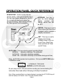
OPERATION PANEL QUICK REFERENCE
START/STOP: Works exactly like the
genset switch. If the genset switch has a
run light and flashes diagnostics, the EC30 run light will also be on when the
genset is running, flash during preheat,
and flash genset fault messages.
UP/DOWN: This key is
used to scroll through
display
choices
and
change values that can
be SET.
ENTER: This key is used to
store values that have been
changed, and to respond to
display commands.
SET: This key is used to
display and change
settable values, such as:
Local Time, Quiet Time
Start and End (QT Start
and QT End).
AUTO GEN: This key selects genset operating Mode:
MANUAL - Operator start/stop. No automatic.
AUTO ON - Automatic start/stop available.
QUIET ON - Automatic start/stop not available during quiet time,
Note: AUTO ON requires two keystrokes. First press AUTO GEN when
in MANUAL mode;
ENTER
for auto
…is displayed. Next press
ENTER for AUTO ON mode.
Do not select AUTO ON mode before reading and understanding this
Instruction Sheet and without following its Safety Precautions!
Note: When operating Mode is not being displayed, pressing the AUTO GEN key will
take the display to its default: Local Time and Generator Mode.
Page 2
Operation of the Energy Command 30
the value. Press ENTER to store the new value.
Also see Setting Local Time.
Overview
This section describes how to use the Energy
Command 30 (EC-30). The Quick Start page
defines key locations and Figures 1, 2, and 3 are
the display screen flow charts.
ENTER Key
ENTER is used to store a value that has been
changed. It is also used to ENTER the SETUP &
INFO DISPLAYS. The ENTER key may also be
required to exit a screen or to acknowledge an
action.
Manual Genset Operation
STOP/START Switch
The Energy Command 30 (EC-30) START/STOP
switch is used to manually start and stop the
genset. This switch functions exactly like the
stop/start switch located on the genset. When
any genset or remote start/stop switch is
operated the EC-30 genset operating Mode is
changed to MANUAL.
Automatic Genset Operation
Safety Features
The EC-30 has safety features to help prevent
automatic operation when it may be unsafe.
Each time the vehicle is moved, the genset
operating mode is changed to Manual. Only if
the vehicle is in a safe location, then use the
AUTO GEN key to select AGS AUTO ON mode.
The EC-30 START/STOP switch has a red
backlight to indicate the genset is running. If the
genset is equipped with diagnostics the EC-30 will
also flash fault messages. It will also decode the
flashing fault message and display a text fault
message.
!WARNING!
DO NOT RUN THE GENSET OR USE THE EC30 AUTO ON OR QUIET ON MODES WHEN THE
RV IS INDOORS OR IN A CONFINED SPACE.
ASPHYXIATION OR CARBON MONOXIDE
POISONING HAZARDS EXIST WHEREVER
GENSET
EXHAUST
GASSES
CAN
ACCUMULATE.
The genset may be started using the
START/STOP switch even if there is no power to
the EC-30. Once the genset is running the EC-30
display will turn on.
Default Display
Local Time and genset operating Mode is the
default display. The genset operating Mode is
shown on the bottom line. If genset Mode is not
shown, the EC-30 returns to the default display
after 10 minutes. To save power, the backlight is
also dimmed after 10 minutes. Touch any key to
turn the backlight on.
This genset/control is not a life support system.
It can stop without warning. Children, persons
with physical or mental limitations, and pets
could suffer personal injury or death. A
personal attendant, redundant power or alarm
system must be used if genset operation is
critical.
The EC-30 safety feature requires an electrical
safety signal input. Check with RV manufacture
as to which safety signal is used. Three different
types can be used:
• Ignition: Input is connected to the vehicle
ignition system (motor homes or van
conversions).
• Brake: Brake light for all trailer, 5th wheel,
and pickup camper installations, or air
brake on diesel motor homes.
• Park:
The
park
signal/neutral
(transmission) from motorized motor
homes or van conversions.
Using the Keys
UP/DOWN Key
UP/DOWN key is used to navigate through the
display menu and to change values or parameters
that can be set by the user. If the UP/DOWN key
is held the display will scroll through the menu.
SET Key
SET is used to select values that can be changed
by the user. Examples include: Local Time, start of
Quiet Time, and end of Quiet Time. Pressing the
SET Key will cause the value to flash (if it can be
changed). The UP/DOWN key is used to change
Page 3
•
When the safety input signal changes from off to
on (or on to off), EC-30 stops the genset and
changes the genset operating Mode to MANUAL.
This prevents unexpected automatic starting
indoors or in confined spaces. Verify the vehicle is
in a safe location, and then use the AUTO GEN
key to select AGS AUTO ON mode.
Brake: Brake light for all trailer, 5th wheel,
and pickup camper installations, or air
brake on diesel motor homes.
• Park:
The
park
signal/neutral
(transmission) from motorized motor
homes or van conversions.
If the safety input is functional, the display will say:
Note also that the EC-30 AUTO ON Mode
requires a confirming keystroke (first AUTO
GEN, then ENTER to confirm). This reduces
risk of unintended AUTO ON operation.
ENTER
for auto
Only press the ENTER key if the genset is in a
safe location for automatic operation.
RV’s can use the AUTO ON or QUIET ON mode
while traveling if the operator re-activates AUTO
ON mode. However each time it is signaled by the
safety input, the genset will be stopped and the
Mode will change to MANUAL. If automatic
operation is desired, press the AUTO GEN key
after parking.
AUTO GEN Key
AUTO GEN is used to select the MANUAL, AUTO
ON, or QUIET ON genset operating Mode. If the
Mode is not displayed, pressing AUTO GEN
immediately exits to Local Time and genset Mode.
Safety Signal Verification
In MANUAL the genset may only be operated by
using a START/STOP switch.
The EC-30 maintains a record of the last change
of the Safety Input signal. If the EC-30 does not
see the Safety Input change in 30 days, it will
prompt the user to re-verify the Safety Input by
activating the safety signal. (i.e. switching the
ignition, changing transmission position, or
operating the parking or trailer brake.)
In AUTO ON the genset will start based on HVAC run
requests and low battery regardless of time of day.
In QUIET ON Mode the genset will not
automatically start during Quiet Time. Prior to
Quiet Time the battery state-of-charge is checked,
and if needed, the genset is started to charge the
batteries before Quiet Time begins.
If the Safety Input signal has not been turned on or
off for 25 days the display will flash the “SAFETY
OFF & ON” screen. Turn the Safety Input signal
off and on, or on and off, to reset the 30 day timer.
If the Safety Input is not verified by day 30 AUTO
GEN is disable. The next time AUTO GEN key is
pressed, the user is prompted to verify Safety
Input signal.
Note: Use of the automatic modes is not allowed if the
house battery voltage is below 9 volts.
Setting Local Time
To set the local time simply press the SET key and
use the UP/DOWN key to change the time. Note
that the display flashes and the hour digit is
underlined. Set the hour value, wait about four
seconds for the underline to move to the right, set
the tens digit, and then wait again to set the
minutes digit, press ENTER.
Verify the Safety Input
The safety input must be verified before automatic
operation is allowed. The first time the AUTO
GEN key is pressed (after power is applied) the
EC-30 requests:
SAFETY
OFF & ON
Setting Quiet Time (QT) Start & End
The Local Time is used to prohibit automatically
starting the genset during Quiet Time. The QUIET
ON mode prohibits the genset from automatically
starting between the start and end of Quiet Time.
To change these times use the UP/DOWN key to
navigate to the QT START or QT END display.
The current setting is shown. Press SET to
change the setting. Use the UP/DOWN key to
change the value and press ENTER to store the
new time.
Where SAFETY = IGNITION, PARK, or BRAKE.
Turn on or off the appropriate signal:
• Ignition: Input is connected to the vehicle
ignition system (motor homes or van
conversions).
Page 4
Adaptive Cycle Management
House Battery Charge Level Indicator
The automatic modes have unique features to
minimize repeatedly starting and stopping the
genset, also called short cycling, and to pre-fill the
battery prior to the start of Quiet Time.
The house battery charge level indicator uses both
short and long term voltage trends to determine
the battery level. It is intended as a guide to the
state-of-charge (SOC) of the battery and its ability
to sustain the load. When the EC-30 is in the
automatic modes it also serves as the default
trigger points for starting and stopping the genset
to charge a low battery. The genset is started
when the bar graph only shows one segment and
stopped when three bars are displayed.
Limiting Short Cycling
Onan genets have a minimum run time of 10
minutes. When in the automatic modes, the EC30 observes the minimum run time, even if the
automatic run request has been satisfied. For
example; suppose the HVAC only needs to run for
6 minutes to cool the coach. The genset will still
continue to run for a minimum of 10 minutes
before stopping.
House Battery Voltage
The house battery voltage can be used to assess
the performance of the charging system and to
estimate the battery SOC. To estimate battery
SOC, no loads should be on and the battery
should not be charging. Ideally, the battery will
have “rested” in this state for 24 hours. Letting the
battery rest for 30 minutes will give an idea but the
SOC estimate will be less accurate.
If a new run request is detected, during the
minimum run, the Adaptive Cycle Management
feature will limit short cycling by extending the run
time as required
The EC-30 also compares the amount of HVAC on
time to the HVAC off time. Based on this ratio, or
percentage, it will continue to run in order to avoid
short cycling. The EC-30 will turn off the genset
after 10 minutes with no run request.
Open Circuit Voltage vs. State-of-Charge
12 Volt Batteries of Various Types
State of
Charge
100%
75%
50%
25%
0%
Quiet Time Pre-Fill
Two hours prior to the beginning of Quiet Time the
EC-30 checks the battery level, and if the batteries
are not full, the EC-30 will start the genset to
charge the batteries.
Battery Electrolyte Type
Liquid
AGM
Gelled
12.6
12.9
12.8
12.4
12.7
12.6
12.2
12.4
12.3
12.0
12.0
12.0
11.8
11.8
11.8
Engine (Chassis) Battery
Preventing Automatic Starting When
Connected to Shore AC
The EC-30 has an input to prevent the genset
from automatically starting when connected to
shore power. For this feature to be active the
installation must include a sensor to detect the
presence of shore power. The Installation section
of this Operation and Installation Manual describes
how this feature is installed.
If a separate engine battery is wired to the EC-30
it is shown in the ENGINE Bat V display. There is
no display if this feature is not wired. This is an
optional feature.
SERVICE IN Display
The SERVICE IN display is a countdown service
hour meter that indicates the genset next required
service interval. To determine specific service
items see the genset manual. When the service
interval has elapsed the display alternates as
shown below.
Note: This is an optional feature, See Testing the
System to determine if this feature is installed.
Using the Displays
The top line of the display is used to show key
system information and the second line of the
display typically shows the genset operating
Mode. Some displays require both lines. If the
genset operating mode is not displayed, the EC-30
returns to the default display after 10 minutes.
See Figure #1 Main Display Map.
SERVICE
DUE
ENTER to
Reset
Display Alternates
Press ENTER to Reset
Service Hour-Meter
Page 5
The SERVICE DUE message is displayed as soon
as the service interval has elapsed.
The
UP/DOWN key still allows navigation through the
main displays and all functions still work. After
the genset is serviced navigate to the SERVICE
DUE message and ENTER to reset the service
interval hour-meter.
If the genset is serviced prior to the next service
reminder, go to the SERVICE IN display and press
SET, press ENTER to reset the service interval
hour-meter.
The SERVICE IN display is also used to display
genset faults and errors that may occur. If a fault
or error has occurred, it will be displayed even if it
no longer exists. When any key is pressed the
message will be cleared.
The last fault message may be displayed by
pressing the STOP switch three times. See the
genset operating manual for details on the error
codes and messages.
Genset Hour-meter
The genset hour meter displays the total elapsed
time the genset has run since the EC-30 was
installed. If the EC-30 is installed on an existing
generator, see the SETUP section of this manual.
Page 6
Setting Up and Testing the Energy Command 30
Overview
This section describes how to Setup and Test the EC30. Before using the EC-30 for the first time check to
be sure that the unit is setup appropriately for the
system. The character < is used to indicate all default
values. Also see Figures #1-4.
The Safety Input is described in detail in the Installation
section of this manual. The Safety Input must be
supplied from:
•
•
Setting GEN TYPE and Safety Type Is
Required for Automatic Operation
•
The very first time the EC-30 is turned on (power
applied) an initial setup procedure begins. The EC-30
requires setup of both the GEN TYPE and Safe Type
prior to allowing automatic operation.
Ignition: Input is connected to the vehicle
ignition system (motor homes or van
conversions).
Brake: Brake light for all trailer, 5th wheel and
pickup camper installations, or air brake on
diesel motor homes.
Park: The park signal/neutral (transmission)
from motorized motor homes or van
conversions.
The displays for the choices are:
The genset type also sets the Service Interval for
service messages and critical automatic starting
parameters. The first service interval is 50 hours for all
models. See SETUP GENSET to change the genset
type after first power up.
Safe Type
NONE
Safe Type
IGNITION
Setting GEN TYPE
First enter the correct GEN TYPE. If no GEN TYPE
has been selected and the AUTO GEN switch is
pressed, the display will say:
Safe Type
BRAKE
GEN TYPE
NONE
GEN TYPES TABLE 1
GEN TYPE
MODEL
NONE<
--QD 10/12
Quiet Diesel
QD 6/8
Quiet Diesel
QD 5.5
Quiet Diesel
GAS/LP
Marquis, Microlite,
Micro Quiet,
GAS RV
Camp Power
Safe Type
PARK
Service In
--250 hours
150 hours
150 hours
150 hours
150 hours
The word NONE will be flashing. Use the UP/DOWN
key and the table above to select the correct genset
type. Press ENTER when the correct genset is
displayed. The next display will say:
SafeType
NONE
Use the UP/DOWN
switch to select the
correct safety type.
Press ENTER when
correct type is displayed.
If setup of the SafeType is skipped, pressing the AUTO
GEN key will begin this procedure.
SETUP & INFO Displays
The SETUP & INFO displays are used to tailor the EC30 to the particular system and application. Refer to
Figure #1 for the various main displays that are
available. To access the SETUP & INFO displays use
the UP/DOWN key to navigate to the SETUP & INFO
display and press ENTER. (See Figure #2: Setup &
Info Displays) The UP/DOWN key now allows scrolling
through the various choices. To access a choice press
the ENTER key. Again the UP/DOWN key is used to
navigate through the available displays.
Use the
ENTER To Exit display to continue through the
previous displays or:
Press the AUTO GEN key anytime to
return to the default display.
Setting Safety Type
Page 7
ENTER. Now navigate to the SETUP GENSET display
and press ENTER. The GEN TYPE will be displayed.
Press SET, the display will flash. Use the UP/DOWN
key to select the GEN TYPE and press ENTER when
the appropriate type is displayed. The GEN TYPE is
stored in permanent memory and will not have to be
changed unless the EC-30 is installed on a different
type genset.
SYSTEM INFO Display
The SYSTEM INFO display allows access to key
information. Pressing ENTER once will display the
reason for the last automatic action. Typical displays
are shown below:
Display
Description
AUTO RUN
HVAC
Genset started for
HVAC run request.
AUTO STOP
HVAC
Genset stopped, HVAC
run request satisfied.
AUTO STOP
SAFETY
Genset stopped safety
input sensed.
SAFETY=IGNITION,
BRAKE, or PARK
AUTO STOP
QT START
Genset stopped at start
of Quiet Time.
AUTO STOP
SHORE ON
Genset stopped, shore
power present.
AUTO STOP
FULL BAT
Genset stopped, battery
full.
AUTO RUN
LOW BAT
Genset started because
battery was low.
AUTO STOP
NO SAFETY
Genset stopped no
safety input sensed for
30 days.
SET Gen Hour Display
If the EC-30 is installed on an existing genset check
the hour-meter on the genset and record the reading.
ENTER the SETUP & INFO menu and navigate to the
SETUP GENSET display. Press ENTER and use the
DOWN key to select the SET Gen hour’s display.
Press SET. The next display says, ENTER to unlock.
This prevents unauthorized changes to the hour-meter.
Press ENTER to continue.
The display will flash. Hold down the UP/DOWN key
and scroll until the left most digit matches the desired
value. Release the UP/DOWN key and wait four
seconds for the underline to move to the next digit to
the right and scroll to its desired value. Set each
successive digit to the right until the correct genset
hours are displayed press ENTER. The value is stored
in permanent memory and will not have to be changed
unless the EC-30 is installed on a different genset.
The hour-meter in the EC-30 and the hour meter at the
genset may differ slightly over time due to small
differences in accuracy.
SETUP AUTO Displays
The SETUP AUTO displays may be used to change
the automatic starting parameters. AUTO< is the
default value. The symbol < indicates the factory
default value.
SafeType Display
VERSION Display
The VERSION display shows the version control
number for EC-30. Should it be necessary to contact
customer service this number will help determine the
specific configuration of your EC-30.
The SafeType display allows the selection of the type
of safety input that is used to prevent automatic
operation. It should be setup the very first time the unit
is turned on as described earlier. If it has not been
setup (SafeType NONE), automatic operation will not
be allowed. If the AUTO GEN key is pressed, the
display below will appear:
SafeType
NONE
SETUP GENSET Displays
The SETUP GENSET displays are used to select the
type of genset used with the EC-30 and to adjust the
genset hour meter.
SETUP GENSET Display
To change the GEN TYPE after initially setting
navigate to the SETUP & INFO display and press
Use the UP/DOWN key to select the correct type of
safety input:
• Ignition: Input is connected to the vehicle
ignition system (motor homes or van
conversions).
Page 8
•
•
Brake: Brake light for all trailer, 5th wheel, and
pickup camper installations, or air brake on
diesel motor homes.
Park: The park signal/neutral (transmission)
from motorized motor homes or van
conversions.
Press ENTER to store in permanent memory. This
will not have to be changed unless the type of safety
input is changed or the EC-30 is installed in a different
application.
Setting START/STOP @ Values - General
When AUTO< is selected Quiet Time prefill (charging
the battery two hours prior to the beginning of Quiet
Time) occurs if the battery level is less than FULL (all
three bars of the level gauge are on).
Care should be taken changing the settings. It is
recommended that these setting only be changed by
qualified personnel that understand the charging
system and have checked its operating voltages.
If STOP @ V has been changed to a user defined
value, then pre-fill occurs whenever the battery voltage
is less than the STOP @ V voltage setting. When the
battery is full or reaches the user set STOP @ V the
genset will be stopped.
START @ V
The START @ V is the voltage to which the house
battery must fall to cause the genset to automatically
start due to a low battery. The default value is Auto
which starts the genset when one bar is displayed in
the battery level indicator. See the Operation section of
this manual. The START @ V voltage range is 10.512.5 volts. A lower voltage will decrease the number of
starts due to a low battery. A higher voltage will
increase the number of start due to a low battery.
Setting the START @ V too high may result in frequent
“false” starts due to a “low battery” start.
Time @ START V
The Time @ START V is the length of time that the
house battery voltage must be below the START @ V
voltage before the genset will automatically start. The
default value is 15 seconds. The range is 5-60
seconds. Setting a shorter time will increase the
number of generator starts due to temporary voltage
dips, (increase the “sensitivity” to voltage dips). Setting
a longer time will decrease the “sensitivity” to
temporary voltage dips.
stop due to a full battery. The default value is Auto
which stops the genset when three bars are displayed
in the battery level indicator. See the Operation section
of this manual. The STOP @ V voltage range is 13.214.5 volts. A lower voltage will not fill the battery as full
but it will reduce the amount of time the genset will run.
A higher voltage will fill the battery to a higher state of
charge, but increase the amount of genset run time. If
the charge system is unable to reach the STOP @ V
voltage, the result will be excessive genset running.
This setting does not change the battery charging
voltage. Do not set STOP @ V above the voltage of
the battery charger.
Time @ STOP V
The Time @ STOP V is the length of time that the
house battery voltage must be above the Stop @ V
voltage to cause the genset to automatically stop due
to a full battery. The default value is one minute. The
range is 1-60 minutes. Setting a shorter time will
decrease the genset run time. Setting a longer time
will increase the length of time the genset runs to
charge the battery.
Selecting Appropriate Values
The selection of the start and stop voltages and the
time required to be at those voltages requires tradeoffs. It is a balance between the number of genset
starts, the length of genset run time, and the desired
battery charge level. The default values have been
selected to ensure that the battery stays charged and
the genset does not run excessively or needlessly start
for temporary voltage excursions. We recommend the
default values be used until the performance of the
system can be assessed.
Setting the START @ V higher will result in more
genset starts and a quicker response to voltage dips.
Setting the Time @ START V shorter will also increase
the response to voltage dips. Both will cause more
genset starts.
Setting the STOP @ Voltage higher will result in more
genset starts and shorter genset runtimes for battery
charging. Setting the Time @ STOP V longer will
increase the genset runtime for battery charging.
Remember charging current falls to very low levels at
the end of charge. Typically it is preferred to use shore
power and not the genset to “top off” or fully charge the
battery. Avoid running lightly loaded gensets. Run
the system through a complete automatic start/stop
cycle after changing setting to confirm proper
performance.
STOP @ V
The STOP @ V is the voltage to which the house
battery must rise to cause the genset to automatically
Page 9
Effect of Increasing START @ V OR Time @ START V
Effect of Increasing
START @ V
Time @ START V
STOP @ V
Time @ STOP V
# Starts
Runtime
Battery Level
More
Less
More
Less
Less
More
Less
More
Higher
Higher
Higher
Higher
TEST SYSTEM Displays
The TEST SYSTEM displays (see Figure #3 TEST
SYSTEM Displays) are used by the installer to verify all
input are connected and operate, and to test run the
genset. After installation the TEST SYSTEM displays
can be used to verify correct operation or to assist in
troubleshooting the system. The various test displays
request a specific action from the operator and
acknowledges that the action has been correctly
observed.
To ensure an orderly process be sure the GENSET
MODE is MANUAL and all inputs are in the off state
before beginning the test. Meaning there are no
HVAC run requests, the ignition is off, the park brake
(or brake lights for a trailer) is off, and there is no shore
power connected.
SAFETY TEST Display
The SAFETY TEST display is used to verify the safety
input is operating correctly. The safety input may be
connected to the:
• Ignition: Input is connected to the vehicle
ignition system (motor homes or van
conversions).
• Brake: Brake light for all trailer, 5th wheel, and
pickup camper installations, or air brake on
diesel motor homes.
• Park: The park signal/neutral (transmission)
from motorized motor homes or van
conversions.
The safety type that is set is displayed.
To check proper operation, navigate to the SETUP &
INFO and press ENTER. Now go to the TEST
SYSTEM display and press ENTER again. SAFETY
TEST will be the first display, press ENTER. The
display will either say IGNITION, or BRAKE, or PARK,
ON & OFF. After the EC-30 sees the change of state
of the safety input it will display the safety type and ok
ENTER. Pressing ENTER will acknowledge its correct
operation and exit back to the SAFETY TEST display.
say TURN ON HVAC1. It makes no difference which
HVAC system is connected to which terminal. Simply
turn on one, and leave all others off. If the EC-30
detects the input, the display will change to say HVAC1
OK Turn Off. Now turn off the HVAC. The displays will
now ask that HVAC2 be turned on. Turn on the next
HVAC unit and follow the displayed instructions. This
process allows a quick test of all HVAC RUN
REQUEST inputs. If there is only one or two HVAC
inputs, use the UP/DOWN key to go to the last display
which is ENTER to Exit.
Run Gen Display
Before testing the genset be sure that the location
is safe for running the genset and that its
installation is completed. This test verifies that the
start, stop, and switched B+ signals between the EC30 and the genset are ok. Navigate to the display that
says ENTER to Run Gen. Pressing ENTER will begin
a start and stop sequence which can only be
interrupted by manually stopping the genset using the
STOP switch. The EC-30 will go through a complete
start and stop sequence and it will display its results as
the test is happening. When the test is complete the
display will say Gen Ok ENTER. Pressing ENTER will
exit back to the display that says ENTER to Run Gen.
To continue testing other system components use the
UP/DOWN key for the next display.
Testing Shore AC Present
This test verifies that the EC-30 can sense when AC
power is available from the utility grid. Before starting
this test be sure that the Shore AC is disconnected.
Turn off the AC breaker at its supply or unplug the
vehicle or trailer from the AC grid system. Do not do
this test with the genset running. Navigate to the
Shore AC Present display and press ENTER. The
display will say Turn On Shore AC. Now plug the
shore AC back in or turn the breaker on. The display
will change to read AC Ok ENTER. Press ENTER to
exit the test.
Exiting TEST SYSTEM
To exit TEST SYSTEM use the UP/DOWN key until
ENTER to EXIT is displayed. Press ENTER and press
DOWN once and ENTER to Exit will be displayed.
Pressing ENTER will exit to the Main Display.
HVAC (RUN REQUEST) Display
The HVAC RUN REQUEST system is tested by
sequentially turning on and off each input. There may
be up to three inputs. From the TEST SYSTEM
display, press ENTER and then navigate to HVAC
RUN REQUEST. Press ENTER. The first display will
Page 10
Installing the Energy Command 30
Overview
Specifications
This section describes how to install the Energy
Command 30 (EC-30).
Operating
Temperature:
Storage
Temperature:
Battery System:
Voltage Range:
Typical Current
Draw:
L x W x D:
General
This system is only for use with Onan Recreational
Vehicle genset (Quiet Diesel gensets, and
Gasoline/LP gensets).
The control circuitry is a 3-wire ground to start/stop
type. Before installing, refer to the System Diagram,
Figure 4, and select the appropriate wiring diagram,
Figures 5-7, for connection to your genset. Consult
an Onan distributor with any questions.
Appendix A shows the Onan gensets that are
compatible with the EC-30 and the correct wiring
figures and harnesses to use for each genset.
!CAUTION! For personal safety and prevention of
equipment damage, only experienced personnel
should install this system. The installer must wear
safety glasses and protective clothing necessary
for personal safety.
Installation Precautions
CAUTION! Always disconnect a battery charger
from its AC source before disconnecting the
battery cables. Otherwise, disconnecting the
cables can result in voltage spikes high enough
to damage the DC control circuits of the genset.
! WARNING! Unexpected starting of the genset
set while working on it can cause severe
personal injury or death. Prevent unexpected or
accidental starting by disconnecting the genset
battery cables {negative (-) first}, or by
disconnecting the remote harness at the genset.
-20 to 70 degrees C
(-4F to 158F)
-40 to 70 degrees C
(-40F to 158F)
12 Volt DC
8 – 35VDC
47mA @ 12V
80.98 x 130.12 x 30.48 mm
(3.188 x 5.125 x 1.20 inches)
INSTALLATION CODES AND
STANDARDS FOR SAFETY
The vehicle builder or EC-30 installer bears sole
responsibility for the appropriate selection of
components, for proper installation and for obtaining
approvals from any authorities having jurisdiction for
the installation. EC-30 is suitable for installation in
accordance with:
• ANSI A 1192 (NFPA No. 1192)-Standard on
Recreational Vehicles
• NFPA No.70, Article 551-Recreational
Vehicles and RV Parks
• CAN/CSA-Z240.6.2 Recreational Vehicles
Federal, State and local codes, such as the California
Administrative Code - Title 25 (RV installation), might
also be applicable. Installation codes and
recommendations may change over time and vary
between countries, states and municipalities. It is
recommended that the standards in Table 2 be
obtained for reference.
TABLE 2 REFERENCE CODES AND STANDARDS
!WARNING!
Arcing can ignite explosive
hydrogen gas given off by batteries, causing
severe personal injury. Arcing can occur if the
negative (-) battery cable is connected and a tool
being used to connect or disconnect the positive
(+) battery cable accidentally touches the frame
or other grounded metal part of the genset set or
vehicle frame. To prevent arcing always remove
the negative (-) cable first, and reconnect it last.
Page 11
<NA for control systems>
NFPA 70
National Electric Code
ANSI A119.2 (NFPA 1192)
Standard on Recreational
Vehicles
California Administrative Code
Title25, Chapter 3
CAN/CSA-Z240.6.2
Recreational Vehicles
National Fire Protection
Association
470 Atlantic Avenue
Boston, MA 02210
Recreational Vehicle
Industry Association
14650 Lee Road
Chantilly, VA 22021
State of California
Documents Section
P.O. Box 1015
North Highlands, CA 95660
Canadian Standards
Association Housing and
Construction Materials Section
I178 Rexdale Blvd
Rexdale, Ontario, Canada
M9W 1 R3
Wires must be protected from all
hot, sharp, and abrasive surfaces.
2) Prepare the chosen location for the genset
controller.
a. Use scissors to cut out the template.
b. Tape the template to the mounting
surface to be cut out, make sure
that the template is “square or level”
with the mounting surface.
c. Using a center punch and a
hammer, punch a mark through the
template for each fastener and at
the perimeters of the cutout area.
d. Remove the template.
3) Drill the cutout starter holes at the four
corners of the cutout area. Cut between
them and remove the cutout.
OEM Supplied Equipment
Required for Installation
Mating Connector Housing
Pins (Up 16 required)
2 or 3 5A DC Inline Fuses
Tools
Pro-Crimper II W/Die 16-20
Contact Extraction Tool
Manufacturer & PN
Tyco/AMP 770583-1
Tyco/AMP 171637-1
Installers choice
Tyco/AMP 189727-1
Tyco/AMP 90760-1
Removing Magnetic Overlay
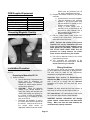
Insert fingernail beside the Stop/Start Switch and lift
gently to remove magnetic overlay.
NOTE: Because the location of the genset
controller will vary by installation, the tools
to be used and the cutout material (wood,
metal, plastic, etc.) will differ. Therefore, the
size of the cutout starter holes and the
procedure for cutting between the starter
holes must be determined by the installer.
4) Drill 1/8-inch diameter holes for the control
panel fastening screws.
5) This completes the preparation of the
mounting hole for the control panel. Do not
mount until wiring is complete.
Wiring Guidelines
Installation Procedure
The wiring for the EC-30 may be single conductors
of 16-20 AWG wire formed into a wiring harness.
The wire must be rated for the environment,
temperature, and applicable standards.
This procedure describes the physical installation of
the unit.
Preparing to Mount the EC-30
1) Select a location:
a. Use the Mounting Template and the
EC-30 itself to determine an
appropriate location. It should be
located in a visible location where it
can be easily operated.
b. CAUTION!
Check the backside
(inside) of the chosen location to
verify that nothing will interfere with
drilling and cutting the opening for
the remote, or with the fasteners,
harness plug, or enclosure on the
back of the EC-30.
c. Determine the feasibility of routing
the control wires from the genset to
the remote. Verify that the route of
the control wires meets all
applicable national and local codes.
Separation from sources of Electro-magnetic
Interference (EMI): All cabling should be installed in
such a way as to comply with the minimum
separation of 5 inches (127 mm) from AC power
sources.
Tension: All wires should be free from tension at
both ends, as well as over the length of each run.
UTP cable bends: UTP cable bends or radii should
be no less than eight times the cable diameter.
!CAUTION! Incorrect connections can damage
genset controls, remote devices, and interconnect
wiring. Make sure that the leads between the
connections are properly connected.
Page 12
Wiring Installation
1. Use wire tags or labels to label each end of
every wire.
Use Figures 5 and 6 to
determine
the
correct
labels
and
connections.
2. At the controller end of the harness, insert
the terminated and labeled wires into the
correct positions in the connector body. Use
Figures 5 and 6 to determine the correct
positions.
3. At the genset end of the harness, insert the
terminated and labeled wires into the correct
positions in the connector body. Use Figures
5 and 6 to determine the correct positions.
Use tie wraps at not less than 20-inch intervals to
keep the wire bundle neat. Use protective sheathing
where necessary to protect the wires from sharp
edges.
Genset Harness Installation
1. Route the harness from the genset to the
control panel, making sure that the
connectors on the harness match the
corresponding connectors at each end.
Wires must be protected from all hot, sharp,
and abrasive surfaces.
!CAUTION! When DC wires are run with AC
wires, electrical induction can occur and
cause operational problems.
Route the
controller harness separately from AC load
wires.
2. Seal any holes where the harness passes
through bulkheads.
!WARNING! Exhaust gases are hazardous and
my cause severe personal injury or death. Seal
all holes to prevent the entrance of exhaust
gasses into the vehicle interior.
Connections (Definitions)
This section describes each connection to the EC-30.
Genset Connections
WIRE #1 BATTERY GROUND (NEGATIVE): This
wire supplies the ground or negative side of the
circuit for the EC-30. It must be supplied from the
genset.
Wire #3 START/PREHEAT: This wire supplies the
start/preheat signal to the genset. It is controlled by
the STOP/START switch and in the automatic mode
by the EC-30.
Wire #4 Request HVAC Active Low: This input
wire supplies a signal to the controller when the
HVAC system requires the genset to run. Typically
it is supplied from a thermostat or the HVAC system
controller. Unlike the other 3 HVAC request inputs,
see wires #10 - #12, this input is an active low or
ground input. This means it requires a transition
from +12V to ground to activate the auto-gen start
function. In contrast to the other 3 HVAC inputs
which require a transition from ground to +12V.
Wire #5 Switched B+ From Genset: This wire is
switched to the battery positive voltage when the
genset is running. It is used to provide a signal for
the genset hour meter and to indicate the genset is
running.
Wire #6 Genset Status Light: This wire supplies a
diagnostic output from the genset that flashes the
red light in the START/STOP switch to indicate a
genset fault. The status light output is decoded by
the EC-30 to display a text fault message.
Power and Voltage Connections
WIRE #7 8-35VDC Power +: This wire is the
positive power supply to the EC-30. It may be
supplied from the distribution side of the DC
disconnect if it is desirable to have all DC loads off
when the disconnect is off. It must be protected by a
5A inline fuse located as close to the battery or
source as possible. Do not install the fuse until
the installation is complete. Install fuse just
prior to testing the installation.
WIRE #8 House Battery Sense 12-24VDC: This
wire supplies the positive sense voltage to the unit
which is displayed as the house battery voltage and
is used to determine the house battery state-ofcharge indicator. It must be connected directly to the
battery. It must be protected by a 5A inline fuse
located as close to the battery as possible. Do not
install the fuse until the installation is complete.
Install fuse just prior to testing the installation.
WIRE #2 STOP OUTPUT: This wire supplies the
stop signal to the genset. It is an active low or
grounded output. It is controlled by the
STOP/START switch and in the automatic mode by
the EC-30.
Page 13
WIRE #9 Engine Battery Sense 12-24VDC: This
wire supplies the positive sense voltage for the
engine starting battery. This is an optional feature.
The engine battery voltage will only be displayed if it
is connected. It must be connected directly to the
battery. It must be protected by a 5A inline fuse
located as close to the battery as possible. Do not
install the fuse until the installation is complete.
Install fuse just prior to testing the installation.
Run Requests from HVAC Systems
There are three inputs for Run Requests from HVAC
systems.
Wire #10 Run Request HVAC #1: This input wire
must supply +12V to the controller when the HVAC
system requires the genset to run. Typically it is
supplied from a thermostat or the HVAC system
controller.
Wire #11 Run Request HVAC #2:
second HVAC unit. See above.
SAFETY INPUTS
THE EC-30 REQUIRES A SAFETY INPUT TO
PREVENT THE GENSET FROM UNEXPECTED
AUTOMATIC STARTING AFTER THE VEHICLE
HAS BEEN PARKED. THE SAFETY INPUT MAY
BE SUPPLIED FROM DIFFERENT SOURCES
DEPENDING ON THE APPLICATION:
VEHICLE TYPE
DIESEL COACH
GASOLINE/LP/DIESEL
-MOTOR HOMES
-VAN CONVERSION
-TRAILER
-5th WHEEL
-PICKUP CAMPER
Used with a
Wire #12 Run Request HVAC #3: Used with a third
HVAC unit. See above.
Sensing AC Shore Power is Present
The two inputs described below are used to prevent
the genset from automatically starting when AC
Shore Power is present.
Do not connect 120VAC or 240VAC line voltage
to the EC-30! It will be damaged and will not be
covered by warranty.
NOTE:AUTOMATIC OPERATION IS NOT
ALLOWED UNLESS THE SAFETY INPUT HAS
BEEN VERIFIED.
During the Safety Input set up choose Ignition,
Brake or Park. The following definitions apply:
•
•
•
Wire #13 AC Present - Ground: Wires #13 and
#14 must be supplied by one of these options.
• UL
Listed
120VAC
to
12-16VAC
transformer.
• UL Listed 120VAC to 12VDC plug-in power
supply. - 12VDC ground side connects to
wire #13. + 12VDC positive side connects
to wire #14.
Note: AC transformer or 120VAC to 12DC converter
is not supplied.
Wire #14 AC Present + Positive: This is the +
positive input. See above.
SAFETY INPUT
-AIR PARK BRAKE
SWITCH
-IGNITION SWITCH
-TRANSMISSION PARK /
NEUTRAL
- IGNITION SWITCH
-TRAILER BRAKE LIGHT
-CAMPER BRAKE LIGHT
Ignition: Input is connected to the vehicle
ignition system (motor homes or van
conversions).
Brake: Brake light for all trailer and 5th wheel
installations, or air brake on diesel motor homes.
Park: The park signal/neutral (transmission)
from motorized motor homes or van
conversions.
The Safety Input must change state when the
vehicle is parked.
This prevents automatic
operation if the vehicle is parked in a garage or
other enclosed space. For example the vehicle
ignition switch changes state from on to off
when vehicle is parked.
Safety Inputs
The two inputs described below are used to prevent
the genset from automatically starting. The voltage
across the input must change from 0VDC to 12VDC
or from 12VDC to 0VDC when the vehicle is parked.
Wire#15 Safety Input – Negative: The negative
input to the safety circuit. See Below.
Wire #16 Safety Input +12V: The positive input to
the safety circuit. See Below.
Page 14
This input should be treated like a relay coil input, or
a light bulb. It must be supplied with both a positive
and a negative. The actual safety switch (ignition,
park brake, or transmission park switch) may be
located in the positive or negative side of the circuit.
These inputs may be wired to be active (on) when
supplied with a negative or positive input. If supplied
with a positive input connect #15 to negative. If
supplied with a negative input connect #16 to +12V.
The drawing below shows how to wire these inputs
for either a negative or positive input.
Wiring Options for Safety Inputs
Option #1 Active High
Ignition Switch Supplying Positive
#15 Safety Input - Negative
#16 Safety Input + Positive
+12VDC
Positive
Option #2 Active Low
Parking Brake Switch Supplying Negative
#15 Safety Input - Negative
#16 Safety Input + Positive
+12VDC
Positive
Final Connections and Testing
This section describes the final connections and the
test procedure to verify that the unit has been
installed correctly and is operating properly.
1. Plug the genset end of the connector into
the genset.
2. Pass the controller end of the harness
through the cutout for the controller.
3. Plug the controller end of the harness into
the controller.
4. Insert the controller in the cutout hole and
secure it with the screws supplied with the
controller.
DO NOT OVER-TIGHTEN
MOUNTING SCREWS, IT MAY DAMAGE
OR DISTORT THE ENCLOSURE.
5. Install the magnetic overlay.
Test Procedure
The following test procedure describes a systematic
method of testing both the installation and operation
of the EC-30. It is highly recommended that the
installer follow these steps:
1. Reconnect the genset negative (-) battery
cable.
2. Insert the fuse in the fuse holders for: Wire
#7 8-35VDC Power, Wire # 8 House Battery
Sense, and Wire #9 Engine Battery Sense.
3. Refer to Setting Up section of this manual to
select the genset type.
4. Setting the Hour-Meter: If the EC-30 is
installed on a new genset this step may
be skipped. See Setting Up section of this
manual.
5. Start and stop the genset using the
Stop/Start switch located at the genset. This
confirms the genset operation.
6. Start the genset at the Automatic Genset
Controller and check the following:
a. The indicator light in the controller
Start/Stop switch flashes while the
genset engine is cranking. This
verifies that the diagnostic wiring is
correct. (Only for units with
diagnostics.)
b. Genset starts and continues to run.
c. The indicator light in the Start/Stop
switch remains illuminated when the
genset is running.
d. Use the Up/Down Switch to the right
of the display to scroll to the Hour
Meter display and confirm that it is
operating.
e. Use the Up/Down Switch to the right
of the display to scroll to the Volt
Meter display and confirm that it is
operating.
7. Stop the genset at the controller and check
the following:
a. The genset stops
b. The indicator light in the Start/Stop
switch turns off.
c. The Hour Meter stops.
8. Refer to Figure #3 and use the TEST
SYSTEM Displays in the Setting Up section
of this manual and follow the test procedure
outlined there to sequentially test all inputs
and outputs.
9. Set the clock to the current local time as
described in the Setting Up section of this
manual.
Page 15
Troubleshooting
If controller functions do not operate properly,
proceed as follows;.
1. Does the genset operate correctly from the
genset controls? If it does not, the problem
is in the genset, not the EC 30 controller.
See the genset Operator, Installation, and
Service Manuals. .
2. If the genset operates correctly from the
genset controls, Confirm that the correct
connection diagram (Figures 5, 6 and 7) was
used, then check EC 30 wiring connections.
3. Confirm that the correct voltages are present
on each terminal.
4. Check all terminal connections on both ends
of the wiring harness. Are harness
connectors properly joined?
5. Repeat the TEST SYSTEM procedure as
described in this Operation and Installation
Manual.
AGS Warning Labels
The unit includes a sheet of adhesive warning
labels. Affix one label at or near each of the
following locations:
• Genset Service Access Panel
• Genset Start/Stop Switch
• Vehicle AC Distribution Panel
• Vehicle AC Transfer Switch
• For towed RV, tow tongue or tongue jack
WARNING
Auto Genset Starting (AGS) installed.
Carbon-monoxide (CO), moving parts, and
shock can cause severe injury or death.
To get service, contact the authorized dealer or
distributor nearest you. Explain the problem and
make an appointment. If you have difficulty in
arranging for service or resolving a problem, please
contact the dealer coordinator or service manager at
the nearest Onan dealer for assistance.
Before calling for service, have the following
information available:
1. The complete model number and serial
number.
2. Software version number, as shown in the
SYSTEM INFO displays.
3. The date of purchase.
4. The nature of the problem.
To enjoy the benefits the product offers requires an
understanding of this manual. If you have ideas for
its improvement we happily accept editorial
comments.
!WARNING! Improper service or replacement of
parts can result in severe personal injury, death,
and/or equipment damage. Service personnel
must be trained and experienced to perform
electrical and/or mechanical service.
Warranty Policy
The ONAN limited warranty covers your Energy
Command 20/30 Control for the first three (3) years
you own your EC 20/30 if purchased at the same
time as an Onan generator. Energy Command
20/30 Controllers sold separately are covered for 90
days.
For complete Onan Limited Warranty details contact
your Onan RV Service and Parts dealer or call 1800-888-ONAN (1-800-888-6626).
Disconnect battery or remote harness at
genset to store or garage RV and before
servicing genset or RV electrical systems.
How to Obtain Customer Service
If you require service, parts, or product literature,
contact the nearest Onan dealer or distributor. To
locate the nearest authorized dealer or distributor, in
the United States or Canada call 1-8OO-888-ONAN
for name and telephone number (This automated
service utilizes touch-tone phones only). By calling
this number, you can also request a directory of
authorized RV servicing dealers:
RV Sales and Service Directory F-919.
Page 16
Appendix A Onan Gensets for Use With the EC-20/30
QUIET DIESELS
MODEL
KW
PRODUCT
EC-20/30
GEN TYPE
Service Connection
IN Hours
Figure
Onan IN
Cable No.
HDCAx
HDKCx
10/12
10/12
Quiet Diesel
Quiet Diesel
QD 10/12
QD 10/12
250
250
5
5
044-00076
044-00076
HDKAx
6/8
Quiet Diesel
QD 7.5/8
150
5
044-00076
HDKBx
HDKBx
5.5
5.0
Quiet Diesel
Quiet Diesel
QD 5.5
QD 5.5
150
150
5
5
044-00076
044-00076
GASOLINE/LIQUID PETROLEUM (LP) (with Status Light)
MODEL
HGJAx
KW
7.0
HGJAx
KY
KYD
5.5
4.0/3.6
4.0/3.6
PRODUCT
Marquis
Platinum
Marquis Gold
MicroQuiet
CampPower
EC-20/30
GEN TYPE
GAS/LP
GAS/LP
GAS/LP
GAS/LP
Service Connection
IN Hours
Figure
150
6
150
150
150
6
6
6
Onan IN
Cable No.
044-00075
044-00075
044-00075
044-00075
GASOLINE/LIQUID PETROLEUM (LP) (without Status Light)
Note 1: This genset model does not support diagnostic fault codes.
MODEL
KVD
KW
2.8/2.5
PRODUCT
CampPower
EC-20/30
GEN TYPE
GAS/LP
Service Connection
IN Hours
Figure
150
7
Onan IN
Cable No.
044-00074
(Note 1)
KV
2.8/2.5
MicroLite
GAS/LP
150
7
044-00074
(Note 1)
•
•
25 foot cables available through Onan IN. Cables have mating connectors for EC20/30
and genset, flying leads for other connections.
Also available is an 18” pigtail, part number 044-00077, without the genset connector
that mates to the EC20/30.
Page 17
Page 18
Page 19
Page 20
Page 21
Page 22
Page 23
Page 24
The mounting footprint for the control is shown below. Select an appropriate mounting location,
make sure there is enough room to install the control panel, and mark the locations for the cutout
area and the mounting holes, as indicated in the illustration. Use a center punch to mark the perimeter of the cutout area.
Depending on the tool to be used (Roto-zip tool
recommended, reciprocating saw, or key hole
saw), determine where to drill the corner starting
holes. The edge of the bit should just touch the
edge of the cutout area. Also lightly punch or mark
the two mounting holes.
Use the perimeter punch marks to draw an outline
on the cutout area on the mounting surface. Drill
the corner starting holes and use the selected tool
to remove the cutout area. File the corners and as
needed to fit. Align the EGR-1 and check that the
mounting hole punch marks line up. Adjust mounting hole marks as needed and drill mounting holes
appropriately for the screws being used to mount
the unit.
NOT TO SCALE
2.1875”
EC-30 OUTSIDE
PERIMETER
1.21875”
2.5”
3.25”
CUTOUT
AREA
5/32” MOUNTING
HOLE FOR #6
MACHINE SCREWS
3.875”
5.1875”
Mounting Footprint
Page 25
1/8” MOUNTING
HOLE WHEN
USING #6 WOOD
SCREWS
Page 26
Cummins Power Generation
1400 73rd Ave. NE
Minneapolis, MN 55432 USA
Phone 1 763 574 5000
Toll-free 1 800 888 6626
Fax 1 763 574 5298
Email www.cumminsonan.com/contact
www.cumminsonan.com
CumminsR, OnanR, the “C” logo, and “Performance you rely on.”
are trademarks of Cummins Inc.
E2007 Cummins Power Generation, Inc. All rights reserved.