1
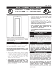
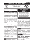
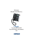
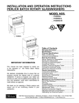
Model U431 (Serial #17978 and up)
OWNER'S MANUAL
Manual No. 513568-4 May 2004, Rev. 0
Need Parts or Service?
We stock the parts you need.
Our Technicians are factory
trained and are certified in the
Stoelting Technicare program.
CALL
Distributor: _________________________
Phone No.:
_________________________
(fill in or affix label)
Model No.: _______________________
Serial No.: _______________________
Purchase Date: ____________________
Start-Up Date:____________________
STOELTING® OWNER'S MANUAL
FOR
MODEL U431
CAB MODEL SOFT-SERVE PRESSURIZED FREEZER
This manual provides basic information about the freezer. Instructions and suggestions are given
covering its basic operation and care.
The illustrations and specifications are not binding in detail. We reserve the right to make changes
at any time without notice, to the freezer and its components, without incurring any obligation to modify
or provide new parts for freezers built prior to date of change.
DO NOT ATTEMPT to operate the freezer until instructions and safety precautions in this manual are
read completely and are thoroughly understood. If problems develop or questions arise in connection
with installation, operation or servicing of the freezer, contact the company at the location listed below.
STOELTING, LLC
502 Hwy 67
Kiel, WI 53042-1600
Tele: 920-894-2293
Fax: 920-894-7029
TABLE OF CONTENTS
Section 1 .............................................................................................................. 1
1.1
1.2
Description .............................................................................................. 1
Specifications.......................................................................................... 2
Section 2 .............................................................................................................. 3
2.1
2.2
2.3
2.4
2.5
Safety Precautions .................................................................................. 3
Shipment & Transit .................................................................................. 4
Freezer Installation ................................................................................... 4
Installing Permanent Wiring ...................................................................... 4
Mix Pump ................................................................................................ 5
Section 3 .............................................................................................................. 9
3.1
3.2
3.3
3.4
3.5
3.6
3.7
3.8
3.9
3.10
3.11
3.12
3.13
3.14
Safety Precautions .................................................................................. 9
Operating Controls and Indicators ............................................................ 9
Important Information Regarding Cleaning and Sanitizing ......................... 11
Disassembly of Freezer Parts.................................................................. 12
Cleaning Disassembled Parts ................................................................. 13
Sanitize Freezer Parts ............................................................................. 13
Cleaning the Freezer ............................................................................... 14
Assembling the Freezer ........................................................................... 14
Sanitizing ................................................................................................ 16
Initial Freeze down and Operation ............................................................ 16
Mix Information ........................................................................................ 17
Operation of Mix Pump ............................................................................ 18
Mix Pump Cleaning ................................................................................. 18
Disassembly and Inspection of Removable Parts ..................................... 18
Section 4 .............................................................................................................. 21
4.1
4.2
4.3
4.4
4.5
4.6
4.7
4.8
4.9
4.10
4.11
Freezer Adjustment ................................................................................. 21
Product Temperature Adjustment ............................................................. 21
Overrun Adjustment ................................................................................. 21
Mix Pump Hose Reposition ..................................................................... 22
Mix Pump Hose Replacement .................................................................. 22
Cab Temp. Adjustment ............................................................................. 22
Drive Belt Tension Adjustment .................................................................. 22
Condenser Cleaning (Air Cooled Freezers) ............................................. 23
Preventative Maintenance ........................................................................ 23
Extended Storage ................................................................................... 23
Troubleshooting ....................................................................................... 24
Section 5 .............................................................................................................. 29
5.1
5.2
How to Order Replacement Parts ............................................................ 29
Parts Lists and Reference Drawings ........................................................ 29
ILLUSTRATIONS
Figure 1
Model U431 Freezer ..............................................................1
Figure 2
Specifications ........................................................................1
Figure 3
Decal Locations .....................................................................3
Figure 4
Water/Electrical Connections .................................................4
Figure 5
Auger Rotation .......................................................................4
Figure 6
Mix Hose Installation...............................................................5
Figure 7
Mix Pump...............................................................................6
Figure 8
3-way Tee ..............................................................................7
Figure 9
Mix Inlet Tube & Probe Assy. Clip...........................................7
Figure 10 Hose Holder...........................................................................7
Figure 11 Operating Controls .................................................................9
Figure 12 Auger Flight Wear & Front Auger Support Bushing Wear .......12
Figure 13 Front Door Disassembly ........................................................13
Figure 14 Auger Flight Removal .............................................................13
Figure 15 Rear Seal Removal ................................................................13
Figure 16 Rear Seal Lubrication ............................................................14
Figure 17 Spring Installation ...................................................................14
Figure 18 Front Door Assembly .............................................................15
Figure 19 Air Bleed Valves ....................................................................16
Figure 20 Draining Sanitizer ..................................................................16
Figure 21 Refrigerated Cabinet .............................................................17
Figure 22 Dispensing Product ...............................................................17
Figure 23 Mix Pumps .............................................................................18
Figure 24 Removable Parts ...................................................................19
Figure 25 Cleaning Air Tube ..................................................................19
Figure 26 Cleaning Feed Tube ..............................................................19
Figure 27 Mix Pump Tube Routing .........................................................19
Figure 28 Potentiometer ........................................................................21
Figure 29 Overrun Adjustment ................................................................21
Figure 30 Temperature Control Cab ......................................................22
Figure 31 Belt Adjustment ......................................................................23
SECTION 1
INTRODUCTION
1.1 DESCRIPTION
The Stoelting U431 floor model freezer is pressure fed.
The freezer is equipped with fully automatic controls to
provide a uniform product. The freezer is designed to
operate with almost any type of commercial soft-serve
or non-dairy mixes available, including ice milk, ice cream,
yogurt, and frozen dietary desserts.
This manual is designed to assist qualified personnel and
operators in the installation, operation and maintenance
of the Stoelting Model U431 pressure freezer.
Figure 1. Model U431 Freezer
Figure 2. Specification
1
1.2 SPECIFICATIONS
MODEL U431
DIMENSIONS
Width: 26-3/4" (68cm)
WEIGHT
925lbs. (419,5 kg)
1 PH
ELECTRICAL
(2 separate pow er
sources required.)
Depth: 39-3/4" (101cm)
975lbs. w/Crate (442 kg)
3 PH
1 PH
3 PH
Left Side Right Side Left Side Right Side Left Side Right Side Left Side Right Side
Total Running Amps
Minimum Circuit Ampacity
HACR Max.Circuit Breaker
Maximum Fuse Size
17.6
31
45
45
17.2
31
45
45
11.6
21
30
30
11.2
21
30
30
20.8
36
50
50
COMPRESSOR
11,690 B.T.U.H. each
DRIVE MOTOR
2 HP each
COOLING
Height: 65-3/4" (167cm)
17.2
31
45
45
14.8
26
35
35
11.2
21
30
30
Water or air cooled. req's 3" (7,5cm) all around clearance and 10" (25cm) top clearance.
Water cooled req's 1/2" (12,5mm) NPT water and drain fittings.
2
SECTION 2
INSTALLATION INSTRUCTIONS
2.1 SAFETY PRECAUTIONS
WARNING
periodically to be sure they have not been painted over,
rubbed off, fallen off, and can be recognized as warning
labels.
CAUTION
Do not attempt to operate the freezer until the safety precautions and operating instructions in the manual are read
completely and are thoroughly understood.
If you are in need of replacement labels, indicate the part
number, type of label, location of label, and quantity required along with your name and address and mail to:
Take notice of all warning labels on the freezer (Fig.3).The
labels have been put there to help you maintain a safe
working environment. The labels have been designed to
withstand washing and cleaning. All labels must remain
legible for the life of the freezer. Labels should be checked
Stoelting, LLC
Commercial Products
502 Hwy. 67
Kiel, WI 53042
Figure 3. Decal Locations
3
2.2 SHIPMENT AND TRANSIT
The freezer has been assembled, operated, and inspected at the factory. Upon arrival at the final destination, the freezer must be checked for any damage which
may have occurred during final transit.
With the method of packaging used, the equipment
should arrive in excellent condition. THE CARRIER IS
RESPONSIBLE FOR ALL DAMAGE IN TRANSIT,
WHETHER VISIBLE OR CONCEALED. Do not pay the
freight bill until the freezer has been checked for damage. Have the carrier note any visible damage on the
freight bill. If concealed damage and/or shortage is found
later advise the carrier within ten days and request inspection. The customer must place claim for damage
and/or shortages in shipment with the carrier. Stoelting,
Inc. cannot make any claims against the carrier.
Figure 4. Water/Electrical Connections
F.
Place the CLEAN-OFF-SERVE switches in the OFF
position before continuing. Figure 11.
2.3 FREEZER INSTALLATION
2.4 INSTALLING PERMANENT WIRING
Permanent wiring is required by local codes, the following procedure must be performed:
WARNING
INSTALLATION MUST BE PERFORMED BY A
QUALIFIED ELECTRICIAN/REFRIGERATION
SPECIALIST. INCORRECT INSTALLATION WILL
VOID THE WARRANTY, AND MAY CAUSE SEVERE DAMAGE TO THE MACHINE. MAY
CAUSE PERSONAL INJURY.
A.
Installation of the freezer involves moving the freezer
close to its permanent location, removing all crating, setting in place, assembling parts, and cleaning.
A.
Uncrate the freezer.
B.
Install the four casters. Turn the threaded end into
the freezer until zero threads are showing. To level,
turn out casters no more than 1/4" maximum, then
tighten all jam nuts.
C.
The freezer must be placed in a solid level position.
NOTE
Three phase freezers in areas of unbalanced electrical loads require special attention when connecting input electrical power. The unbalanced leg of
power (called wild or high) must be connected to
L2 in the junction box.
NOTE
Accurate leveling is necessary for correct drainage
of freezer barrel and to insure correct overrun.
D.
The freezer must have a minimum of 3" (7,5cm)
-6" (15cm) high ambient conditions- of space on all
sides and 10" (25cm) at the top for proper circulation.
CAUTION
FAILURE TO PROVIDE ADEQUATE VENTILATION WILL VOID WARRANTY!
E.
Refer to the nameplate at the rear of the freezer for
specific electrical requirements. Make sure the power
source in the building matches the freezer nameplate requirements. Bring the wires into the junction
boxes through the access holes in the bottom rear of
the freezer. Figure 4.
B.
Remove the lower back panel and the two junction
box covers located at the bottom of the freezer.
C.
lnstall permanent wiring according to local code.
D.
Check the auger shaft rotation by placing the MAIN
DRIVE switch in the CLEAN position. Auger shaft
rotation is clockwise as viewed through the clear
plastic front door. If the rotation is not clockwise,
turn main electrical power OFF. Then reverse L1
and L3 electrical power lines to the junction box
(three phase only). Re-check auger shaft rotation.
Figure 5.
Water-cooled freezers need an adequate water
supply. Install 1/2" (12,7mm) pipe or 1/2" (12,7mm)
inside diameter copper water line to the freezer.
Connect water outlet to a drain using a 1/2"
(12,7mm) inside diameter line. Automatic washer
hoses work well for final connections. All water
connections must comply with local codes. Fig. 4.
CAUTION
FLUSH ALL WATER LINES BEFORE INSTALLATION. IN STORES WITH SEDIMENT IN WATER,
ADD SUITABLE FILTER OR STRAINER TO WATER
INLET.
Figure 5. Auger Rotation
4
2.5 MIX PUMP
A.
Mix Pump Hose Installation
Follow the steps below to install the mix pump hose.
1. Turn pump on.
2. Feed one end of mix pump hose into the entering
or pick-up hose side (left) of black cover.
3. Gently push the hose into the black cover until it
begins to feed.
6" (15cm)
Figure 6. Mix Hose Installation
4. Allow the hose to feed itself thru the pump
until 6" (15cm) remains on the entering side.
7. Turn pump on.
8. Allow remaining 6" (15cm) of tubing to feed thru pump
until hose adapter prevents further feeding.
5. Turn pump off.
6. Connect mix pump hose to pickup hose
adapter using small hose clamp.
9. Turn pump off.
10.Connect free end of mix pump hose to 3-way
Tee as shown in Figure 7. When all connections
are complete the 3- way Tee must be lower than
the black pump housing. Figure 8.
CAUTION
DO NOT TWIST MIX PUMP HOSE.
5
B.
Connect 1/2 inch (12,7mm) I.D. plastic food grade
tubing to mix check valve (Item 7) and then to the
mix container. Observe check valve flow arrow.
Secure with hose clamps. Then place assembly
thru hole in cover and install retainer clip. See
Figure 9.
C.
Connect 1/2 inch (12,7mm) I.D. plastic food grade
tubing between the large port of air/mix tee and
refrigerated mix transfer line. Secure with large
hose clamp or equivalent. See Figure 9.
CAUTION
AIR/MIX TEE MUST REMAIN BELOW THE
BLACK COVER/CLAMP. IF THE TEE IS
ABOVE THE PUMP MIX WILL DRAIN TO THE
AIR COMPRESSOR RESULTING IN PUMP
DAMAGE.
D.
Connect mix low cords. Figure 9.
Figure 7. Mix Pump
6
Å Refrigerated
Mix Transfer
Line
Large PortÆ
(Air/Mix)
Å 3-way Tee
Figure 8. 3-way Tee
Low Mix Cord
Ì
Cover
È
Mix
Container
É
Retainer
Clip
Figure 9. Mix Inlet Tube & Probe Assy. Clip
Ç
Hose Holder
Figure 10. Hose Holder
7
8
SECTION 3
INITIAL SET-UP AND OPERATION
3.1 SAFETY PRECAUTIONS
SAFE OPERATION IS NO ACCIDENT; observe these
rules:
A.
B.
C.
D.
E.
F.
G.
Know the freezer. Read and understand the operating instructions.
Notice all warning labels on the freezer.
Wear proper clothing. Avoid loose fitting garments,
and remove watches, rings or jewelry which could
cause a serious accident.
Maintain a clean work area. Avoid accidents by
cleaning the area and keeping it clean.
Stay alert at all times. Know which switch, push
button or control you are about to use and what
effect it is going to have.
Disconnect electrical power for maintenance.
Never attempt to repair or perform maintenance on
the freezer until the main electrical power has been
disconnected.
Do not operate under unsafe operating conditions. Never operate this freezer if unusual or excessive noise or vibration occurs.
A.
Spigot Switch
When the spigot handle is opened the SPIGOT
switch will start the auger drive and refrigeration
systems. When the spigot handle is closed, the drive
B.
Clean-Off-Serve Switch
The CLEAN-OFF-SERVE switch is a three position
toggle switch used to control the operation of the
refrigeration system and auger. When the switch is
placed in the CLEAN position, the refrigeration system will be off and auger will rotate for cleaning.
When the switch is placed in the OFF position, the
refrigeration system and auger will not operate.
When the switch is placed in the SERVE position,
the refrigeration system and auger will operate automatically. The switch should be placed in the SERVE
position for normal operation.
C.
Cabinet-Off-On Switch
The CABINET-OFF-ON switch is a two position
toggle switch. When the switch is placed in the OFF
position, the lower cabinet refrigeration system will
not run. When the switch is placed in the ON
position, the lower cabinet refrigeration system will
run until the preset temperature is reached; then
cycle ON and OFF to maintain that temperature.
D.
Cab Indicator Light
A flashing light indicates the cab OFF-ON switch is
in the OFF position, no refrigeration. Place the OFFON switch in the ON position for cab refrigeration.
E.
Pump Switch
The pump motor switch is a two position toggle
switch. When the switch is placed in the OFF
position, the pump will not run. When the switch is
placed in the ON position, the pump will run until the
preset pressure is reached, then cycle ON and OFF
as product is drawn to maintain that pressure.
F.
Standby/Serve Switch
The standby/serve switch is a two position toggle
switch. When the switch is placed in the Standby
position the freezer will cycle to maintain a
temperature below 41°F. When the switch is in the
Serve position the freezer will cycle to maintain a
servable product.
G.
Freezing Switch
The freezing switch is a two position toggle switch.
When the switch is placed in the ON position
the freezer will be forced to run 30 seconds after the
temperature control is satisfied.
3.2 OPERATING CONTROLS AND INDICATORS
Before operating the freezer, it is required that the operator know the function of each operating control. Refer to
Figure 11 for the location of the operating controls on the
freezer.
Freezing
StandbyCleanServe
Off-Serve
Dispense Rate
Adjusters
Low Mix
Cab
Light
Off-On
Cab Indicator
Light
StandbyServe
CleanOff-Serve
Low
Mix
Light
Pump Switch
Figure 11. Operating Controls
WARNING
The CLEAN-OFF-SERVE switch must be placed
in the OFF position when disassembling for
cleaning or servicing. The freezer must be disconnected from electrical supply before removing any access panel.
9
H.
Dispense Rate Adjusters
The dispense rate adjuster limits the opening of the
spigot. To adjust product dispense rate, turn the
adjusting knob clockwise for slower flow and counterclockwise for faster flow.
I.
High Head Pressure Cut Out
If the head pressure exceeds 445 PSIG (28 bar) air
cooled and water cooled, the high head pressure
cutout will trip. The reset button can be accessed
from the side of the freezer.
J.
Low Mix Light
The low mix light will illuminate when the liquid level
in the mix container drops below two gallons.
K.
Front Door Safety Switch
The front door safety switch prevents the auger from
turning when the front door is removed. The switch
is open when the door is removed and closed when
the door is properly installed.
10
CLEANING
·
Is the removal of soil materials from a surface.
·
Is a prerequisite for effective sanitizing.
3.3 IMPORTANT INFORMATION REGARDING
CLEANING AND SANITIZING
Soft serve and shake freezers require special
consideration when it comes to food safety and
proper cleaning and sanitizing.
NOTE
An UNCLEAN surface will harbor bacteria that can
defy sanitizing efforts.
The following information specifically covers issues
for cleaning and sanitizing frozen dessert freezers.
This information is meant to supplement a
comprehensive food safety program.
Bacteria can develop and resist sanitizing efforts
within a layer of soil material (milkstone). Thorough
cleaning procedures that involve milkstone
removal are critical for operators of frozen
dessert machines.
Soil Materials Associated with Frozen Dessert
Machines
SANITIZING
·
Kills bacteria.
·
Can be effective on clean surfaces only.
·
DOES NOT clean or remove milkstone.
MILKFAT/BUTTERFAT – As components of icecream/frozen custard mix, these soils will
accumulate on the interior surfaces of the machine
and its parts. Fats are difficult to remove and help
attribute to milkstone build-up.
NOTE
Using a SANTITIZER on an unclean surface
will not guarantee a clean and safe frozen
dessert machine.
MILKSTONE – Is a white/gray film that forms on
equipment and utensils that come in contact with
dairy products. These films will accumulate slowly
on surfaces because of ineffective cleaning, use of
hard water, or both. Milkstone is usually a porous
deposit, which will harbor microbial
contaminants and eventually defy sanitizing
efforts.
Proper Daily Maintenance:
The Only Way to Assure Food Safety and
Product Quality
Proper daily maintenance can involve a wide variety
of products and procedures. Overall, the products
and procedures fall into three separate categories.
(Please note that this is a brief overview intended for
informational purposes only.)
1. CLEANING – This involves draining mix from the
freezer barrel and rinsing the machine with
water. Next, a cleaner is run through the
machine. Then, the machine is disassembled
and removable parts are taken to the sink for
cleaning.
Once milkstone has formed, it is very difficult to
remove. Without using the correct product and
procedure, it is nearly impossible to remove a thick
layer of milkstone.
(NOTE: general-purpose cleaners DO NOT remove
milkstone.) This can lead to high bacteria counts
and a food safety dilemma.
IT IS BEST TO CONTROL MILKSTONE ON A
DAILY BASIS BEFORE IT CAN BECOME A
SIGNIFICANT FOOD SAFETY PROBLEM.
2.
MILKSTONE REMOVAL – Since almost all
cleaners do not have the ability to remove
milkstone, the use of a delimer becomes
necessary. Although this procedure may not be
needed on a daily basis, it will usually follow the
cleaning procedure. It requires letting a delimer
solution soak in the machine for an extended
period of time. Individual parts are also soaked
in a deliming solution for an extended period of
time (more about delimers in Additional
Information).
3.
SANITIZING – After the machine has been
cleaned and contains no milkstone, the
machine is reassembled. Then a FDA-approved
sanitizing solution is run through the machine to
kill bacteria. The machine is then ready for food
preparation.
In addition to food safety, milkstone can cause
premature wear to machine parts which can add to
costs for replacement parts or possibly more
expensive repairs if worn machine parts are not
replaced once they have become excessively worn.
Important Differences Between Cleaning and
Sanitizing
CLEANING vs. SANITIZING
It is important to distinguish between cleaning and
sanitizing. Although these terms may sound
synonymous, they are not. BOTH are required for
adequate food safety and proper machine
maintenance.
11
The ideal concentration of chlorine needs to be 100
ppm (as stated by the FDA).
As a recommended cleaner and sanitizer for your
frozen dessert machine, STERA-SHEEN has proven
to be one of the best daily maintenance products for:
·
CLEANING – Thorough removal of all solids
including butterfat and milk fat.
NOTE
Follow the directions on the container for proper
concentration.
·
MILKSTONE REMOVAL – Complete removal of
milkstone.
There are two main factors that contribute to falling
chlorine concentrations in a sanitizing solution.
·
SANITIZING – FDA-approved no rinse sanitizer
for food contact surfaces.
1.
PRODUCT USE – As the chlorine in the
solution is being used, chlorine concentrations
fall.
2.
TIME – As time passes, small amounts of
chlorine “evaporate” from the solution. (That is
why you can smell it.)
Additional Information
THE USE OF DELIMERS
A delimer is a strong acid that has the ability to
dissolve milkstone. This type of chemical may
become necessary once high levels of milkstone
have developed. While these products are very
effective for removing HIGH levels of milkstone, they
are not ideal for two reasons:
1.
2.
Sanitizing solutions should not be allowed to fall
below 100 ppm chlorine. New solutions should be
mixed once old solutions become ineffective.
3.4 DISASSEMBLY OF FREEZER PARTS
PRODUCT SAFETY – Strong acids are
dangerous chemicals and handling them
requires safety
WARNING
Moving machinery can grab, mangle and dismember. Place the CLEAN-OFF-SERVE toggle
switch in the OFF position before disassembling
for cleaning or servicing. Placing the CLEAN-OFFSERVE toggle switch in the SERVE position during cleaning or servicing may result in serious
personal injury.
MACHINE DAMAGE – Strong acids will attack
metal and rubber causing premature wear of
parts. The use of a delimer needs to be closely
monitored to avoid damage to machine surfaces
and parts.
With proper daily use of STERA-SHEEN or it’s
equivalent, there is no need for the use of a
DELIMER.
Before using the freezer for the first time, complete freezer
disassembly, cleaning and sanitizing procedures will need
to be followed. Routine cleaning intervals and procedures
must comply with the local and state health codes.
Inspection for worn or broken parts should be made at
every disassembly of the freezer for cleaning or other
purposes. All worn or broken parts should be replaced to
ensure safety to both the operator and the customer and
to maintain good freezer performance and a quality product. Two normal wear areas are the auger flights and front
auger support bushing (see Figure 12).
DO NOT USE BLEACH
·
BLEACH HAS ABSOLUTELY NO CLEANING
PROPERTIES.
·
BLEACH IS CORROSIVE. It can and will
damage components of the machine causing
premature wear and metal corrosion.
GENERAL PURPOSE CLEANERS
To disassemble the freezer, refer to the following steps:
General purpose cleaners do not have the ability to
remove milkstone. Milkstone will become a problem
if not remedied with additional products and
procedures.
Wear Line
È
THE USE OF CHLORINE TEST STRIPS
“Test strips” are used to determine concentrations of
active chlorine in sanitizing solutions. To use the
strips, tear off a small portion and submerge it into
the sanitizing solution. Then, compare the color
change to the color key on the side of the test strip
dispenser to determine the approximate chlorine
concentration.
Figure 12. Auger Flight Wear & Front Auger
Support Bushing Wear
12
A.
Disassembly Of Front Door
1. Remove the front door by turning off the circular
knobs and then pulling the front door off the studs.
2. Remove the air bleed valve by unscrewing the knob
while holding the valve stem from behind. Remove
the compression spring and push air bleed valve
through the rear of the front door.
3. Remove the spigot through the bottom of the front
door (see Figure 13). Remove all O-rings from
spigots and air bleed valve.
Figure 15. Rear Seal Removal
3.5 CLEANING DISASSEMBLED PARTS
Disassembled freezer parts require complete cleaning,
sanitizing and air drying before assembling. Local and
state health codes will dictate the procedure required.
Some state health codes require a four sink process (prewash, wash, rinse, sanitize, air dry), while others require
a three sink process (without the pre-wash step). The
following procedures are a general guideline only. Consult
your local and state health codes for procedures required
in your location.
Figure 13. Front Door Disassembly
B. Disassembly Of Auger
A.
To clean the freezer parts, disassemble all parts.
(Refer to section 3.4 for the disassembly of freezer
parts.)
B.
Place all front door and auger parts in clean 90° to
110°F (32°C to 43°C) water and wash thoroughly
(four sink procedure only).
C.
Place all parts in 90° to 110°F (32°C to 43°C) , mild
detergent water and wash thoroughly.
D.
Rinse all parts with clean 90° to 110°F (32°C to
43°C) water.
F.
Sanitize all freezer parts following procedures out
lined below.
1. Remove the front auger support by pulling it
straight out of the freezer barrel.
2. Remove the plastic bearing from the front auger
support.
3. Remove the auger by pulling slowly and rotating
out of the freezer barrel. As the auger is
withdrawn, remove each plastic flight and spring
from the auger. Be careful not to scratch inside of
freezer barrel when removing flights or auger.
Remove the spring from each auger flight.
3.6 SANITIZE FREEZER PARTS
A. Use a sanitizer mixed according to manufacturer's
instructions to provide a 100 parts per million strength
solution. Mix sanitizer in quantities of no less than 2
gallons of 90° to 110°F (32°C to 43°C) water. Allow
the sanitizer to contact the surfaces to be sanitized
for 5 minutes. Any sanitizer must be used only in
accordance with the manufacturer's instructions.
B.
Figure 14. Auger Flight Removal
4.
Keep the rear of the auger tipped up once it is
clear of the freezer barrel.
5. Wipe spline lubricant off hex end of auger with a
paper towel. Remove the rear seal. Figure 15.
13
Place all parts in the sanitizing solution for 5 minutes,
then remove and let air dry completely before assem
bling in freezer.
3.7 CLEANING THE FREEZER
É
CAUTION
Lubricate
with
Socket
Lubricant
Risk of Product Damage
Do not use acid cleaners, strong caustic compounds
or abrasive materials to clean any part of the freezer
exterior or plastic parts.
É Ê
É
Lubricate with Petrogel
Figure 16. Rear Seal Lubrciation
The exterior should be kept clean at all times to
preserve the lustre of the stainless steel. A good
grade of stainless steel has been used on the
freezer to ease clean-up. To remove spilled or dried
mix, simply wash the exterior in 90° to 110°F (32°C
to 43°C) , soapy water and wipe dry.
Do not use highly abrasive materials as they will
mar the finish. A mild alkaline cleaner is recommended. Use a soft cloth or sponge to apply the
cleaner. For best results, wipe in the direction of the
grain of the steel.
A.
Clean the rear seal surface from inside of the freezer
barrel.
B.
Using this sanitizing solution and the large barrel
brush provided, sanitize the barrel by dipping the
brush in the sanitizing solution and brushing the
inside of the barrel.
C.
Remove the rear drip tray by pulling from side panel.
Clean and replace drip tray.
C.
Lubricate the hex drive end of auger with a small
amount of white socket lubricant. A small container
of socket lubricant is shipped with the freezer.
D.
Screw the springs onto the studs in plastic flights.
Spring must be screwed into the flights completely to provide proper tension (see Figure 17).
3.8 ASSEMBLING FREEZER
To assemble the freezer parts, refer to the following steps:
NOTICE
Petro-Gel sanitary lubricant or equivalent must be
used when lubrication of freezer parts is specified.
Figure 17. Spring Installation
NOTICE
The United States Department of Agriculture and
the Food and Drug Administration require that lubricants used on food processing equipment be certified for this use. Use Lubricants only in accordance
with the manufacturer's instructions.
A. Assemble all O-rings onto parts dry, without lubrication. Then apply a thin film of sanitary lubrication
to exposed surfaces of the O-rings.
B.
C.
Lubricate rear seal area on auger shaft with a thin
layer of sanitary lubricant. Install the rear seal O-ring.
Lubricate outside of rear seal O-ring with sanitary
lubricant.
E.
Install first flights to bottom of auger, rotate, add
successive flights from bottom as the auger is pushed
slowly into the freezer barrel. Carefully engage auger
with drive socket in speed reducer by rotating auger
slowly and pushing on end of auger.
F.
Apply a thin film of sanitary lubricant to the inside and
outside of the front auger support bearing, then place
on the front of the auger. Assemble the front auger
support onto the auger bearing.
NOTICE
Position the front support on auger so legs do not
interfere with the pin on the back of the front door
assembly. Front door must push auger in slightly
when it is being tightened to prevent the rear seal
from leaking.
Install stainless steel rear seal adapter into rear seal
dry (without lubricant). Lubricate inside surface of
rear seal adapter and install onto auger shaft. DO
NOT lubricate outside of rear auger seal (see Figure
16).
14
G.
Assemble O-rings onto the spigot dry, without
lubrication. Then apply a thin film of sanitary lubricant
to the outside of the O-rings and spigot bodies.
H.
Install the spigots through the bottom of the front
door ( see Figure 18).
Figure 18. Front Door Assembly
I.
Assemble the air bleed valve O-ring onto the air
bleed valves. Position the O-ring in groove close to
the wide part. Apply a thin film of sanitary lubricant to
the O-rings.
J.
Insert the air bleed valves from the back of the front
door. Install compression springs onto air bleed
valves, then screw knobs on finger tight.
K.
Apply a thin film of sanitary lubricant to the door seal
O-rings, and fit into the grooves on the rear of the
front door.
L.
Place the front door assembly on the mounting studs
and push front door against the freezer carefully.
M.
Secure front door assembly by placing the knobs on
the studs and alternately tighten opposite corners
until finger tight only. Do not overtighten. Proper
O-ring seal can be observed through the transparent
front door.
N.
Move the spigot handles to the closed position.
15
3.9 SANITIZING
Sanitizing must be done after the freezer is clean and just
before the freezer is filled with mix. Sanitizing the night
before is not effective. However, you should always clean
the freezer and parts after using it.
C.
Let sanitizing solution fill the freezer barrel to air bleed
valve, then close the valve by pulling out to lock in
place.
D.
Place the CLEAN-OFF-SERVE toggle switch in
the ON position while pressing the CLEAN switch.
WARNING
The United States Department of Agriculture and
the Food and Drug Administration require that
all cleaning and sanitizing solutions used with
food processing equipment be certified for this
use.
When sanitizing the freezer, refer to local sanitary regulations for applicable codes and recommended sanitizing
products and procedures. The frequency of sanitizing must
comply with local health regulations. Mix sanitizer according to manufacturer’s instructions to provide a 100
parts per million strength solution. Mix sanitizer in quantities of no less than 2 gallons of 90°F to 110°F 90° to
110°F (32°C to 43°C) water. Allow sanitizer to contact the
surfaces to be sanitized for 5 minutes. Any sanitizer must
be used only in accordance with the manufacturer’s instructions.
Figure 20. Draining Sanitizer
E.
Check for leaks when the freezer barrel is first
pressurized with sanitizing solution.
1. Check for leaks at the plastic front door, the
O-rings may not be sealed.
2. Check the drain located at the center of the
Drip Tray for leaks coming from the rear of the
Rear Auger Seal.
3. Check inside cab unit for leaks at hose connections.
F.
Using a sanitized soft bristle brush or equivalent,
dipped in sanitizing solution, clean mix container.
G.
After five minutes, open spigot to expel sanitizing
solution. Drain all solution from freezer using all three
spigots (See Figure 20).
H.
Close the spigot and place the mix pump switch
and the CLEAN-OFF-SERVE switch in the OFF
position.
Air Bleed Valves
Figure 19. Air Bleed Valves
CAUTION
The freezer is now sanitized and ready for adding mix.
Risk of Product Damage
Avoid prolonged contact of sanitizer with freezer parts.
Prolonged contact of sanitizer with freezer may cause
corrosion of stainless steel parts.
A.
Prepare 3 gallons of sanitizing solution following
manufacturer's instructions, and pour into storage
container.
B.
Place the mix pump switch in the ON position and
open air bleed valve on the front door by pushing
valve in and holding (see Figure 19).
3.10 INITIAL FREEZE DOWN AND OPERATION
This section covers the recommended operating procedures to be followed for the safe operation of the freezer.
16
A.
Sanitize just prior to use according to instructions
outlined in this manual.
B.
Prepare the desired amount of mix and then fill each
storage container with approximately 3 gallons or
more of mix. Place a container(s) of mix in the refrigerated cabinet. If drawing from a storage container,
place the draw tube through the cover to the bottom
of the container. If drawing from a bag in a box, remove the cap, push out all of the air, and insert the
adaptor.
The freezer is designed to dispense the product at a
reasonable draw rate. If the freezer is overdrawn, the
result will be a soft product and air pops. If this should
occur, allow the freezer to run for approximately 30
seconds before dispensing additional product. After a
while the operator will sense or feel when the freezer is
beginning to fall behind, and will slow down on the rate
of draw so as not to exceed the freezer's capacity.
Do not operate the freezer when the MIX LOW light is
on or with less than 1-3/4" (4.4 cm) of mix in the
mix container. Refill the mix container immediately.
Mix Low
Sensor
Figure 21. Refrigerated Cabinet
C.
D.
Place the mix pump switch in the ON position. The
mix pump switch is located in the upper left hand
corner, inside the refrigerated cabinet. Immediately
open the spigot and let approximately 8 ounces of
liquid mix with sanitizing solution drain out of the
spigot.
Close the spigot and open the air bleed valve on the
front door by pushing the valve in and holding. Allow
the barrel to fill until the mix level is 1/2" (2.7 cm)
below air bleed valve, then release valve and pull
closed to lock in place.
E.
Start the compressor and drive by placing the
CLEAN-OFF-SERVE switch in the SERVE position
F.
The product will be ready to serve after the compressor and drive have cycled off, or in approximately
minutes.
12
G.
Spigot Rate Adjusters
Figure 22. Dispensing Product
3.11 MIX INFORMATION
Mix can vary considerably from one manufacturer to
another. Differences in the amount of butter-fat content and
quantity and quality of other ingredients have a direct
bearing on the finished frozen product. A change in freezer
performance that cannot be explained by a technical
problem may be related to the mix.
Proper product serving temperature varies from one
manufacturer's mix to another. Mixes should provide a
satisfactory product in the 17° to 20°F (-7° to -6°C) range.
Diet and low-carb mixes typically freeze to proper consistency at higher temperatures.
The refrigeration is automatically actuated when
the spigot is opened. For normal dispensing, open
the spigot no more then 90°. (This is when the
handle knob is pointed directly away from the front
door.). This position provides excellent control over
the product and aids in making desired shaped
portions. Spigot Rate Adjusters are located under
the Header Panel, to the immediate right of each
Spigot Handle. Turning the Spigot Rate Adjuster
clockwise will increase the dispense rate.
(see Figure 22)
When checking the temperature, stir the thermometer in
the frozen product to read the true temperature.
Mix does not improve with age. Old mix, or mix that has
been stored at too high a temperature, can result in a
finished product that is less than satisfactory from the
appearance and taste standpoint. To retard bacteria growth
in dairy based mixes, the best storage temperature range
is between 36° to 40°F (2.2° to 4.4° C).
17
3.12 OPERATION OF MIX PUMP
The pump switch is located on the front of the freezer.
When the pump switch is placed in the ON position, the mix
pump motor will be actuated to pump mix into the freezer
cylinder. When the set pressure is reached, the mix pump
will shut off automatically. When the switch is placed in the
OFF position, the mix pump will be inoperative.
C.
NOTICE
Any cleaning procedure must always be followed
by sanitizing before filling freezer with mix. (Refer to
section 3.3)
NOTE
The mix pump motor is equipped with an internal
overload that will “trip”, disabling the pump when the
motor is overloaded. Consult the trouble shooting
section for corrective information.The internal overload will automatically reset after cooling. If the condition continues, contact a qualified service person.
3.13 MIX PUMP CLEANING
The mix pump is approved for CIP (clean in place) and is
thoroughly cleaned as cleaning solutions are pumped thru
the freezer. We recommend completely disassembling
the pump and connecting tubing every 14 days for inspection
of parts to confirm the CIP has been properly performed. If
any residue is detected clean or replace those parts as
outlined below.
CAUTION
1. Place CLEAN-OFF-SERVE switch in CLEAN position. Allow the auger to agitate for 5 to 10 minutes.
Risk of Product Damage
Mix pump hose must be repositioned every 1 -2 weeks
or 60 hours of operation. Failure to comply will result
in reduced mix pump liquid capacity, dispense stoppage, popping, and possible mix pump hose leakage. Hose leakage may damage the pump roller assembly and void the factory warranty.
A.
The over-run adjustment is preset at the factory. If an
adjustment becomes necessary, refer to Section 4.
2. Remove suction tube from mix container. Draw off the
mix remaining in freezer barrel.
3. Pump 2 gallons (7.5 liters) of cold potable water thru
freezer until water at spigot is free of mix.
4. Pump 2 gallons (7.5 liters) of 90° to 110°F (32°C to
43°C) detergent solution water thru freezer. The use
of soft water is recommended, along with dishwashing
detergents such as “Joy,” “Dawn,” or equivalent.
Mix Operation: The peristaltic mix pump contains
one continuous mix pump hose. When looking at the
face of the peristaltic mix pump, the left side of the
hose is the suction or pickup. The right side of the
hose is the discharge. Mix is drawn up the suction
side of the hose and transferred thru the discharge
side to the freezer (see Figure 23).
5. Place mix pump switch in OFF position. Open spigot
to relieve remaining pressure.
6. Place CLEAN-OFF-SERVE switch in OFF position.
Air Operation: The air compressor operates whenever
the peristaltic mix pump is running. Air enters thru a
check valve on the piston downstroke. The air is
discharged thru a second check valve, on the piston
upstroke. The air and mix join at the tee and then
travel to the freezer.
3.14 DISASSEMBLY AND INSPECTION OF
REMOVABLE PARTS
Inspection of removable parts should be made whenever
maintenance is performed or pump requires disassembly.
WARNING
Æ
B.
Hazardous Moving Parts
Revolving pump head can grab, mangle, and cause
serious crushing injury. The Power switch must be
placed in the OFF position for cleaning and power
must be disconnected when disassembling or
servicing.
Hose
Holder
Mix
Intake Æ
Mix
Æ Discharge
CAUTION
Æ 3-way Tee
System Under Pressure
Never disconnect hoses from freezer or pump without
first opening spigot to relieve pressure.
Figure 23. Mix Pumps
18
NOTE
If the mix lines or air line is difficult to remove, soften
with a rag soaked in hot water. Hose connections
may be sprayed with Haynes Sanitary Lubricant for
ease of removal. Do not loosen or remove the mix
pump cover wingnuts. Maintain the mix pump hose
in its operational condition.
9. Sanitize assembled freezer as per instructions
outlined in Section 3.9).
1. Loosen clamp and remove air hose from pump
compressor.
2. Loosen clamp and disconnect mix pump hose.
Remove the pickup hose, mix check valve and pickup
hose adapter (and bag adapter if applicable) as an
assembly from mix container.
3. Completely disassemble both hose assemblies and
check valve. Place hoses, tee, check valve assembly, and pickup hose adapter in 90° to 110°F (32°C to
43°C), mild detergent water and wash thoroughly. Use
soft bristle brushes to clean inside of fittings. Rinse
all parts in clean 90° to 110°F (32°C to 43°C) water
(see Figure 24).
Figure 25. Cleaning Air Tube
4. Carefully inspect each part for wear or damage.
Replace worn or damaged parts.
5. Wash feed tube and air tube with 90° to 110°F detergent water and brushes provided. Rinse with clean,
90° to 110°F water (See Figure 25 and 26).
6. Prepare two gallons (7.5 liters) of sanitizing solution
using a USDA certified grade sanitizing solution.
Sanitize all removed parts, then air dry.
Figure 26. Cleaning Feed Tube
7. Check Hose Service Record decal to determine if
hose reposition or replacement is required at this
time.
Pump
Compressor
8. Reassemble both hose assemblies per the diagram
located on the inside of the cab door. Reconnect
assemblies to the pump and discharge hose, using
the clamps. (See Figure 27 or refer to Section 2.5 Mix
Pump).
Figure 24. Removable Parts
Figure 27. Mix Pump Tube Routing
19
20
SECTION 4
MAINTENANCE INSTRUCTIONS
The mix pump has been preset at the factory to produce a
product with approximately 40% overrun. Because of
differences in mix formulation, temperatures and barometric pressure, this figure may vary. It will be necessary
for approximately 2 gallons (7,5 liters) of mix to be
pumped thru the freezer before changes in the product
are noticeable due to adjustments in overrun.
4.1 FREEZER ADJUSTMENT
This section is intended to provide maintenance personnel with a general understanding of the freezer adjustments. It is recommended that any adjustments in this
section be made by a qualified person.
4.2 PRODUCT TEMPERATURE ADJUSTMENT
A potentiometer is used to control the product temperature. To change the temperature of the product, follow the
steps below:
A.
Loosen the two screws under the header display
sign, then pull sign out and down.
B.
Use a screw driver to make desired adjustment. A
label near the potentiometer will give complete instructions. Figure 28.
Overrun is controlled by the length of the air compressor
piston stroke within the piston cylinder. Lengthening the
stroke within the cylinder will increase overrun. Conversely, shortening the stroke will decrease overrun. To
perform an overrun adjustment, refer to the following
procedure:
A. Turn the mix pump switch to the OFF position.
Disconnect both power sources/circuit breakers.
B. Remove the lower back panel from freezer.
C. On air compressor side of pump, locate the long/
slender piston rocking arm. The rocking arm downward travel is limited by a stationery cam. On the face
of the cam there is an overrun setting indicator plate
numbered 3 thru 8 and an adjustment knob. Figure
29.
Figure 28. Potentiometer
4.3 OVERRUN ADJUSTMENT
The product when served is a combination of air and mix.
Overrun is a measure of the amount of air blended into the
mix.
Ê
Overrun Adjustment
Overrun can be expressed in terms of the amount of
weight loss for a given volume. For example, if a pint of
liquid mix weighs 18 ounces (510 grams) and a pint of
frozen product with air added weighs 12 ounces (340
grams), the overrun is said to be 50 percent "18 oz. (510
grams) - 12 oz. (340 grams) = 6 oz. (170 grams)", (6 /12)
x 100 = 50%.
Figure 29. Overrun Adjustment
D. The overrun setting is indicated by a pointed pin.
E. To adjust overrun, loosen the allenhead screw
(located within the center of the adjustment knob)
with the 5/32" (4mm) allen wrench provided. Rotate
the adjustment knob counterclockwise to a higher
number for higher overrun, or clockwise to a lower
number for lower overrun. Each number multiplied by
10 represents the overrun percentage (ie: #4 = 40%
overrun).
The overrun can be checked by placing a one pint
container on an ice cream scale and zeroing out the scale.
Then fill a one pint container with frozen product. The
container should be filled over the top and leveled with a
straightedge. The product should not contain any air
pockets. When weighed on an ice cream scale, one pint
(473 milliliters) of product should weigh 12 to 13 ounces
(340 to 368,5 grams).
21
F. Tighten the allen screw, then place the wrench back
in its clip. Replace the lower back panel and secure
with the four screws. Turn the mix pump power switch
to the ON position.
CAUTION
NEVER DISCONNECT HOSES FROM FREEZER
OR PUMP WITHOUT FIRST OPENING SPIGOT
TO RELIEVE PRESSURE.
3. Disconnect mix pump hose at each end.
4.4. MIX PUMP HOSE REPOSITION (every one or
two weeks.)
4. Grasp the discharge hose end with one hand
and turn the pump on. Pull down on the hose
until all of the remaining hose is removed from
the pump.
NOTE
Mix pump hose must be repositioned every 1 - 2
weeks. Failure to comply will result in reduced mix
pump liquid capacity, dispense stoppage, popping,
and possible mix pump hose leakage.
5. Connect new mix pump hose to pick-up hose
adapter, using small clamp.
6. Insert free end of hose into the pick-up (suction
side) hose side of the black cover. Gently push
the hose into the black cover until it begins to
self-feed. Allow the hose to feed itself through
the pump until the pick-up hose adapter prevents further feeding, then turn the pump off.
1. Run cleaning solution through pump.
2. Turn pump off and relieve any pressure by
opening the spigot.
3. Grasp the pick-up hose end of the mix pump
hose with one hand and turn the pump on. Pull
down on the pick-up hose end until 12 to 14"
(30-1/2 to 35-1/2cm) of tubing has reverse fed
through the pump, then turn the pump off.
7. Reconnect mix pump hose to T using small
clamp. Pump is now ready to sanitize.
4.6 CAB TEMPERATURE ADJUSTMENT
A temperature control is used to control cab temperature.
To change the temperature, disconnect electrical power
and then follow the steps below:
4. Loosen small clamp at the pick-up hose
adapter and (Viewed from Back) disconnect
mix pump hose.
5. Cut 7-1/2" (19 cm) off the end of the mix pump
hose.
A.
Remove the six screws holding the left side panel
and remove panel.
B.
Use a small screwdriver to adjust the temperature
control. Turn counterclockwise for a warmer temperature and clockwise for a colder temperature. It
will take about an hour for the cab temperature to
change. Figure 30.
6. Reconnect mix pump hose to adapter.
7. Continue normal operation. Mix hose will
automatically reposition itself with adapter near
black cover.
NOTE
Each hose is long enough for 3 repositions before
replacement is required. Record each event on
Hose Service Record decal.
4.5 MIX PUMP HOSE REPLACEMENT
NOTE
Mix pump hose must be replaced when tubing cannot be further repositioned (every four to eight
weeks). Failure to comply will result in hose failure
and possible pump damage.
Figure 30. Temperature Control Cab
1. Run cleaning solution through pump.
C.
Install side panel and secure with the six retaining
screws.
4.7 DRIVE BELT TENSION ADJUSTMENT
To check belt tension, refer to Figure 29 and follow the
steps below:
2. Turn pump off and relieve any pressure by
opening the spigot.
WARNING
THE MIX PUMP SWITCH MUST BE IN THE
“OFF” POSITION WHEN SERVICING OR
CLEANING PUMP.
WARNING
DISCONNECT ELECTRICAL SUPPLY TO
FREEZER BEFORE SERVICING.
22
A.
Remove either side and back panels.
B.
Press firmly on one belt. Figure 31.
NOTE
If the condenser is not kept clean, loss of refrigeration efficiency will result.
4.9 PREVENTATIVE MAINTENANCE
It is recommended that a preventative maintenance schedule be followed to keep the freezer clean and operating
properly. The following steps are suggested as a preventative maintenance guide.
WARNING
NEVER ATTEMPT TO REPAIR OR PERFORM
ANY MAINTENANCE ON FREEZER UNTIL ALL
MAIN ELECTRICAL POWER HAS BEEN DISCONNECTED.
The United States Department of Agriculture and the
Food and Drug Administration require that lubricants
used in food zones be certified for this use. Use lubricants
only in accordance with the manufacturer's instructions.
Figure 31. Belt Adjustment
C.
D.
When the tension is properly adjusted, the outside
of the depressed belt should be approximately in
line with the inside of the other belt.
A.
Check for any unusual noise or condition and repair
immediately.
If an adjustment is necessary, loosen the four motor
plate retaining nuts, adjust belt tension then re
tighten the four nuts.
B.
2. Check the condenser for dirt. (Refer to Section
4.8).
4.8 CONDENSER CLEANING (AIR-COOLED
FREEZERS)
The condenser requires periodic cleaning. To clean the
condenser, refer to the following steps:
WARNING
NEVER ATTEMPT TO REPAIR OR PERFORM
MAINTENANCE ON FREEZER UNTIL ALL MAIN
ELECTRICAL POWER HAS BEEN DISCONNECTED.
NOTE
Some freezers have a condenser filter, to clean remove and wash in warm soapy water. Rinse in clean
water and shake dry, taking care not to damage
filter in any way.
Visually inspect the condenser for dirt.
B.
If the condenser is dirty, place a wet towel over the
condenser.
C.
Using compressed air or CO2 tank, blow out the dirt
from the back of the condenser. Most of the dirt will
cling to the wet towel.
4.10 EXTENDED STORAGE
Refer to the following steps for winterizing the freezer or
for storing the freezer over any long period of shutdown
time.
A.
Clean thoroughly with warm detergent all parts that
come in contact with mix. Rinse in clear water and
dry all parts. Do not sanitize.
NOTE
Do not let cleaning solution stand in freezer barrel
or mix pump during the shutdown period.
B.
Remove, disassemble, and clean the front door,
auger shaft, and mix pump. Leave disassembled
during the shutdown period.
C.
Place plastic auger flights in a plastic bag with a
moist paper towel. This will prevent flights from
becoming brittle if exposed to dry air over an
extended period of time (over 30 days).
CAUTION
THIS PROCEDURE EMITS A LOUD NOISE.
D.
Month Checks
1. Check drive belts for wear and tighten belts if
necessary. (Refer to Section 4.7.)
NOTE
Belt life will be increased if new drive belts are tightened after two or three weeks of operation.
A.
Daily Checks
An alternative method is to clean with a condenser
brush and vacuum.
23
D.
For water-cooled freezers that are left in unheated
buildings, or buildings subject to freezing, the water
must be shut off and disconnected. Disconnect
fittings at water valve inlet and water outlet lines at
the freezer. The fittings are located at the rear of the
freezer. Run the compressor for 2 - 3 minutes to
open water valve. Blow out all water, first through
water inlet, then through water outlet lines with air or
carbon dioxide. Also drain water supply line to the
freezer.
E.
Place the mix pump ON-OFF switch, and the
CLEAN-OFF-SERVE switch in the OFF position.
F.
Disconnect from the source of electrical supply in
the building.
4.11 TROUBLESHOOTING
The Troubleshooting Table lists the common problems
that can occur to the freezer.
24
FREEZER
PROBLEM
Drive motor (auger)
"kicks-out", or does
not run.
FREEZER POSSIBLE CAUSE
1. Power to freezer is off.
2. Drive motor overloaded.
3. Low line voltage.
4. Product too hard.
5. Front door not installed securely.
Compressor does not
operate.
1. Power to freezer if off.
2. Drive motor overloaded.
REMEDY
1. Check power to freezer.
2. Wait 15-20 min. for Thermo overload
to reset.
3. Check, must be +\-10% of
nameplate voltage.
4. Raise overrun and/or product
temperature. (See Section 4.3 or 4.2)
5. Install front door securely.
4. Compressor internal overload is
cut-out.
5. Front door not installed securely.
1. Check power to freezer.
2. Wait 15-20 min. for Thermo overload to
reset.
3. Check, must be +/-10% of nameplate
voltage.
4. Check condenser (air cooled)(See Sect.
4.8), or water suppy (water cooled).
5. Install front door securely.
Product too soft.
1. Temperature setting is too high.
2. Product break down.
3. Standby/Serve Switch in Standby
position.
1. Adjust temperature. (See Section 4.2)
2. Fill with fresh product.
3. Place Standby/Serve Switch in Serve
position.
Freeze-up. (Product
will not dispense
easily.)
1. Temperature setting is too low.
2. Low overrun setting.
3. Low pump pressure.
4. Large air pocket in barrel.
5. Auger turning counter-clockwise.
1. Adjust temperature. (See Section 4.2)
2. Raise overrun. (See Section 4.3)
3. Check pump pressure.
4. Purge air from barrel.
5. Change rotation to clockwise.
Rear auger seal leaks.
1. Rear auger seal not lubricated.
2. Seal missing or installed wrong.
3. Worn or scratched shaft.
1. Lubricate seal. (See Section 3.8)
2. Check. (See Section 3.8)
3. Replace shaft.
Spigot leaks.
1. Spigot parts are not lubricated.
2. Chipped or worn o-rings.
3. O-rings on spigot installed wrong.
4. Nicks or scratched on front door
where spigot is located.
1. Lubricate. (See Section 3.8)
2. Replace O-rings.
3. Remove spigot and check O-rings.
4. Replace front door.
Drive belts slipping or
squealing.
1. Drive belt tension not correct.
2. Worn belt(s).
3. Temperature setting is too low.
4. Low overrun.
1. Adjust belt tension. (See Section 4.7)
2. Replace belts.
3. Adjust temperature. (See Section 4.2)
4. Check for air leak.
Mix temperature too
warm in cab.
1. System low on refrigerant.
2. Temperature control set too
warm.
1. Add refrigerant. (Refrig. Service)
2. Remove left side panel and locate
temperature control and follow
instructions on decal.
Mix temperature too
cold in cab.
1. Temperature control set too cold.
1. Remove left side panel and locate
temperature control and follow
instructions on decal.
3. Low line voltage.
25
MIX PUMP
1. PU MP MOTOR D OES N OT R U N
Power to pump i s off.
Supply power to pump.
Low voltage.
C heck for low li ne voltage.
Mi x pump hose jammed i nsi de black cover/clamp.
D i sconnect pump from power source. Remove four
cover/clamp thumb screws. Separate cover/clamp
halves and remove outer half. Remove jammed hose.
Re-i nstall cover/clamp and ti ghten four thumb screws
securely. Allow motor thermal overload to reset. See
Sec. 2.5 for hose replacement. D o not use jammed
porti on of hose.
Pump motor overloaded.
Allow i nternal thermal overload to reset; determi ne
overload cause and repai r.
Pressure swi tch on pump i s defecti ve.
C ontact your local Stoelti ng D i stri butor.
D efecti ve motor/capaci tor
C ontact your local Stoelti ng D i stri butor.
D efecti ve toggle swi tch.
C ontact your local Stoelti ng D i stri butor.
2. PU MP OPER ATES B U T C YLIN D ER WILL N OT FILL
NOTE 1: A PROPERLY WORKING PUMP WILL FILL AN 8 OZ. C UP WITH MIX IN ABOUT 9 SEC OND S.
NOTE 2: IMMED IATELY AFTER A "BAG C HANGE" THE PUMP MAY BE UNABLE TO RE-ESTABLISH IT'S
PRIME WITH THE SYSTEM AT OPERATING PRESSURE. IN THIS C ASE, TURN THE PUMP OFF. D RAW 2-3
PINTS TO REDUC E SYSTEM PRESSURE TO ZERO. TURN PUMP ON. PURGE REMAINING AIR IN MIX BAG
AND PIC K-UP HOSE.
IMPOR TAN T: B efore connecting the pick-up hose to the mix bag, purge the mix bag of air to the extent
possible.
Out of Mi x.
Repleni sh mi x supply.
MIx pump hose ki nked i nsi de black cover/clamp.
Follow mi x pump hose jammed repai r. (See #1 above.)
Hoses assembled i ncorrectly.
Refer to di agram for correct hose connecti ons.
Mi x pump hose servi ce li fe i s exceeded.
Reposi ti on/replace mi x pump hose. See Sec. 2.5.
Mi x pump hose not connected to freezer.
C onnect mi x pump hose to freezer.
Ice crystals i n mi x.
C ompletely thaw mi x pri or to use.
Mi x bag drawn agai nst adapter.
Assure bag i s clear of pi ck-up tube.
Forei gn objects i n mi x.
C lear blockage. Use fresh mi x.
Mi x C heck Valve i s i nstalled backwards.
Observe flow arrow for proper ori entati on.
3. OVER R U N TOO LOW OR N O OVER R U N
Overrun setti ng too low.
Increase overrun setti ng.
Ai r leak.
Ti ghten all hose clamps.
Ai r compressor not pumpi ng air.
C ontact local Stoelti ng D i stri butor.
4. OVER R U N TOO H IGH
Mi x pump hose servi ce li fe i s exceeded.
Reposi ti on/replace mi x pump hose.
Out of mi x.
Repleni sh mi x supply.
Overrun setti ng too hi gh.
D ecrease overrun setti ng.
Pi ck-up leg of mi x pump hose i s collapsi ng.
See Secti on 2.5.
NOTE: ALSO SEE "2" ABOVE.
26
5. REPLACEMENT MIX PUMP HOSE WON'T FEED THROUGH PUMP
Feeding hose into discharge hole of mix pump cover.
Feed hose into pick-up side of cover.
Hose ends not cut squarely.
Carefully cut hose end off squarely (no tails).
Force feeding too quickly.
Gently and slowly assist feeding of hose up into pick-up
hose side of cover.
Pump motor not running.
Turn on motor switch. Also see Item 1 above.
6. AIR EXITING MIX PICK-UP HOSE
Pickup tube check valve missing.
Contact local Stoelting Distributor.
7. DISPENSED PRODUCT AIR "POPS"
Overrun setting too high.
Reposition/replace mix pump hose.
Mix pump hose service life is exceeded.
Reposition/replace mix pump hose.
Overdrawing the freezer's capacity.
Reduce dispense rate.
Recent "mix-out" condition.
Open spigot fully and allow excess air to "belch" out.
NOTE: ALSO SEE 2 & 4 ABOVE.
8. MIX LEAKAGE FROM PUMP
CAUTI ON: To prevent mix pump damage from dried mix deposits, immediately disassemble and clean
pump.
Mix pump hose service life is exceeded.
Remove mix pump hose. Disconnect pump from power
source. Remove mix pump cover/clamp. THOROUGHLY
rinse three squeeze rollers using a spray bottle filled
with hot water. Thoroughly clean all mix from pump. See
Sec. 2.5 for hose replacement.
9. PUMP HAS POOR CAPACITY
Lift and run limits are exceeded.
Pump is limited to 10' lift, 20' run.
NOTE: Also see 2, 4, 6 & 7.
10. PUMP IS NOISY/SQUEAKING
NOTE: THE ACTION OF THE AIR COMPRESSOR ROCKING ARM CREATES A REPETITIVE CLICKING
SOUND DURING OPERATION. THIS IS NORMAL.
11. MIX IN AIR HOSES
Air/mix tee above black cover/clamp.
Air/mix tee must be below black cover/clamp.
Air leak.
Tighten all hose clamps.
Mix hose on wrong air/mix tee fitting.
Refer to diagram for correct hose connections.
27
28
SECTION 5
HOW TO ORDER REPLACEMENT PARTS
5.1 HOW TO ORDER REPLACEMENT PARTS
To assure the receipt of the proper replacement parts,
supply your serviceperson with the following information:
A.
Model number of equipment.
B.
Serial number of model (stamped on nameplate)
C.
Part number, part name, and quantity needed.
5.2 PARTS LIST AND REFERENCE DRAWINGS
The following lists and drawings will aid the user when
ordering parts or servicing.
2
Item Stoelting P/N Qty.
Description
1
Door (Side ID Grooves)
38mm (1.5 inch) Spigot Ext.
64mm (2.5 inch) Spigot Ext.
76mm (3 inch) Spigot Ext.
Rosette Cap
Castle Top O-Ring
Door w/Pins - CE
"O" Ring Spigot Extension
38mm (1.5 inch) Spigot Ext.
64mm (2.5 inch) Spigot Ext.
76mm (3 inch) Spigot Ext.
Rosette Cap
1
2177427
2177072
2177073
2177074
232734
624677
2177588
624654
2158070
2159688
2157869
232732
1
1
NOTE
If you are replacing a front door without side grooves
you mustorder the extensions and rosettes also.
29
2
3
4
5
6
7
8
9
10
11
12
13
14
1158091
3159696
3158086
624598
624664
625133
508135
482019
624614
624520
694200
482004
2110116
1
2
1
4
1
2
AsReq
4
2
2
2
2
2
Actuator, Door Safety
Spigot, Outside
Spigot, Center
O-Ring
O-Ring (CS)
O-Ring (Silicone)
Lubricant, Petrogel
Knob Black
O-Ring (CS)
O-Ring
Spring Comp.
Knob
Valve Stem
30
AUGER PARTS
Drawing
Index No.
1
2
3
4
5
6
7
8
Part
Number
Qty.
Description
2104552
149003
381804
694255
4151178
624678
1151859
667868
1
1
6
6
1
1
1
1
Auger Front Support
Front Bearing
Plastic Flight
Spring
Auger
Rear Seal "O" Ring
Rear Seal Adaptor
Rear Seal
MISCELLANEOUS PARTS
Description
Part No.
Haynes Spray 12 oz.(340 grams) -------------------- 508017
Petro-Gel Tube 4 oz. (113 grams) -------------------- 508135
Spline Lubricant 2 oz. (57 grams) -------------------- 508048
Brush 4"x 8"x16" (10cm x 20cm x 40,5cm) ------- 208135
Brush 2.5"x 4"x12" (6,5cm x 10cm x 30,5cm) ---- 208146
Brush .25"x 4"x14" (,6cm x 10cm x 35,5cm) ----- 208380
Brush 1"x3.5"x18" (2,5cm x 9cm x 45,5cm) ------ 208465
Drip Tray --------------------------------------------------- 744273
Drip Tray Grid --------------------------------------------- 417006
31
Figure 7. Mix Pump
32
DECALS
Qty.
Part Number
Description
2
2
2
1
2
1
1
2
4
1
2
324200
324798
324797
324800
324799
324141
324509
324014
324686
723525
324106
2
3
2
2
1
2
1
1
2
2
3
1
2
2
2
2
1
1
1
1
324346
324107
324208
723552
723517
H.P. Manual Reset
Clean-Off-Serve
Standby/Serve
Cab Off-On
Pump Off On
Caution, Haz. Rot. Blade - Front Panel
Cleaning - Right Side
Auger Rotation - Evap. Enclosure Rear
Danger - Start Auto, on Evap. Support between belts & motors support brkt.
Winterizing, Attach to water hose near bottom
Caution - Elec. Wiring Mat'ls must conform between water couplings, one rear
panel bottom
Caution - Haz. Mov. Parts, on inside of mtr support brkt @ rear
Caution - Haz. Mov. Parts, on cond. bkt. rear & (2) on evap. enclosure sides
Attn - Ref. Lk Chk, on evap. enclosure sides
Tag - Supply volt., inside J-Box
Card - Inside one J-Box
ID Tags, Back Panel Top
Add. Vent Back Panel Ctr Top
Made in U.S.A. - Back panel
Caution - Rot. Shaft, on gearbox support bracket
Field Connections, J-Box cover, outside
Danger Elec.Shock, J-Box covers outside, back panel bottom
Warm/Cold, @ T-Stat
Night/Serve - Temp. Control Bracket
Use copper cond. only, inside both J-boxes
Wired According to, on elec. schematic envelope
Elec. Schematic Envelope
Water Inlet - Back panel above inlet coupling
Header Panel Decal (Stoelting Logo)
Header Panel Decal (Stoelting Swirl)
Header Panel Decal (A & W Logo)
324548
324103
324151
324125
324242
324565
324158
324566
130000
324065
324803
324804
324806
33
34
35
36
S UC TI ON
D IS CH AR GE
S UC TI ON
D I SC HAR GE
37
38
SU CT IO N
D IS CH ARG E
S UC TIO N
D IS CH AR GE
39
40
41
42
WARRANTY
SOFT SERVE / SHAKE FREEZERS
1. Scope:
Stoelting, LLC warrants to the first user (the “Buyer”) that the freezer cylinders, hoppers, compressors, drive motors,
speed reducers, auger and auger flights of Stoelting soft serve / shake freezers will be free from defects in materials
and workmanship under normal use and proper maintenance appearing within five (5) years, and that all other
components of such equipment manufactured by Stoelting will be free from defects in material and workmanship
under normal use and proper maintenance appearing within twelve (12) months after the date that such equipment is
originally installed.
2. Disclaimer of Other Warranties:
THIS WARRANTY IS EXCLUSIVE; AND STOELTING HEREBY DISCLAIMSANY IMPLIED WARRANTY OF MERCHANTABILITY OR FITNESS FOR PARTICULAR PURPOSE.
3. Remedies:
Stoelting’s sole obligations, and Buyer’s sole remedies, for any breach of this warranty shall be the repair or (at
Stoelting’s option) replacement of the affected component at Stoelting’s plant in Kiel, Wisconsin, or (again, at
Stoelting’s option) refund of the purchase price of the affected equipment, and, during the first twelve (12) months of
the warranty period, deinstallation/reinstallation of the affected component from/into the equipment. Those obligations/remedies are subject to the conditions that Buyer (a) signs and returns to Stoelting, upon installation, the
Checklist/Warranty Registration Card for the affected equipment, (b) gives Stoelting prompt written notice of any
claimed breach of warranty within the applicable warranty period, and (c) delivers the affected equipment to Stoelting
or its designated service location, in its original packaging/crating, also within that period. Buyer shall bear the cost
and risk of shipping to and from Stoelting’s plant or designated service location.
4. Exclusions and Limitations:
This warranty does not extend to parts, sometimes called “wear parts”, which are generally expected to deteriorate
and to require replacement as equipment is used, including as examples but not intended to be limited to o-rings,
auger seals, auger support bushings and drive belts. All such parts are sold
AS IS.
Further, Stoelting shall not be responsible to provide any remedy under this warranty with respect to any component
that fails by reason of negligence, abnormal use, misuse or abuse, use with parts or equipment not manufactured or
supplied by Stoelting, or damage in transit.
THE REMEDIES SET FORTH IN THIS WARRANTY SHALLBE THE SOLE LIABILITY STOELTING
AND THE EXCLUSIVE REMEDY OF BUYER WITH RESPECT TO EQUIPMENT SUPPLIED BY
STOELTING; AND IN NO EVENT SHALL STOELTING BE LIABLE FOR ANY INCIDENTAL OR
CONSEQUENTIAL DAMAGES, WHETHER FOR BREACH OF WARRANTY OR OTHER CONTRACT BREACH, NEGLIGENCE OR OTHER TORT, OR ON ANY STRICT LIABILITY THEORY.