1
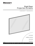
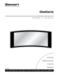
Luxus A / SR-1 Electriscreen O W N E R ’ S M A N U A L To the Owner Installation Instructions Operating the Screen Maintenance LXSR-0903 T O T H E I N S TA L L E R : B E S U R E T O L E AV E T H I S M A N U A L W I T H T H E O W N E R . Printed in U.S.A. ©2003 Stewart Filmscreen Corporation. Luxus A / SR-1 Electriscreen O W N E R ’ S M A N U A L Contents To The Owner . . . . . . . . . . . . . . . . . . . . . . . . . . . . . . . . . . . .2 Preparing The Installation . . . . . . . . . . . . . . . . . . . . . . . . . . .4 Step 1. Hanging The Case . . . . . . . . . . . . . . . . . . . . . . . . . . .6 Step 2. Electrical Hook-up . . . . . . . . . . . . . . . . . . . . . . . . . . .8 Adjusting The Screen Extension . . . . . . . . . . . . . . . . . . . . .14 Operating The Screen . . . . . . . . . . . . . . . . . . . . . . . . . . . . .14 Screen Care And Cleaning . . . . . . . . . . . . . . . . . . . . . . . . .16 Troubleshooting . . . . . . . . . . . . . . . . . . . . . . . . . . . . . . . . . .17 Luxus A/SR-1 Electriscreen: Owner’s Manual 1 TO THE OWNER Congratulations on your purchase of the finest optical viewing screen available anywhere in the world! Please take a moment to review this manual, it will help ensure you many years of trouble-free service from your new Stewart Filmscreen product. About your Luxus A Series Electriscreen This is Stewart’s most popular electric roll up unit because it can accommodate screen sizes up to 66” x 122” (LX138W). Typically, the screen housing is hidden above the ceiling, and the screen descends through a slot in the ceiling. About your Luxus SR-1 Series Electriscreen The SR-1 electric roll-up screen is identical to the Luxus A Series with the exception that its housing is more styled and can be installed with minimal architectural changes to your room. The installation, operation, and care are the same for the Luxus A Series and the Luxus SR-1 Series Electriscreens. The size and weight of the various Luxus Electriscreen models are listed in the charts in Figure 1. Figure 1: Luxus Electriscreen models – sizes and weights Video Format (4:3/1.33:1 Aspect Ratio) 2 Luxus A Model # Luxus SR1 Model # Image Diagonal Image Height Image Width Weight LX060V- SR060V- 60” 36” 48” 35 lbs. LX072V- SR072V- 72” 43” 57” 40 lbs. LX084V- SR084V- 84” 50” 67” 45 lbs. LX090V- SR090V- 90” 54” 72” 50 lbs. LX100V- SR100V- 100” 60” 80” 55 lbs. LX120V- SR120V- 120” 72” 96” 65 lbs. Stewart Filmscreen Corporation HDTV Format (16:9/1.78:1 Aspect Ratio) Luxus A Model # Luxus SR1 Model # Image Diagonal Image Height Image Width Weight LX082H- SR082H- 82” 40 1/2” 72” 50 lbs. LX092H- SR092H- 92” 45” 80” 55 lbs. LX100H- SR100H- 100” 49” 87” 60 lbs. LX110H- SR110H- 110” 54” 96” 65 lbs. LX123H- SR123H- 123” 60” 107” 70 lbs. 135” 66” 118” 70 lbs. LX135H- Wide Screen Format (1.85:1 Aspect Ratio) Luxus A Model # Luxus SR1 Model # Image Diagonal Image Height Image Width Weight LX082W- SR082W- 82” 39” 72” 50 lbs. LX091W- SR091W- 91” 43” 80” 55 lbs. LX100W- SR100W- 100” 48” 89” 60 lbs. LX114W- SR114W- 114” 54” 100” 70 lbs. LX126W- SR126W- 126” 60” 111” 75 lbs. 138” 66” 122” 70 lbs. LX138W- A/V Format (1:1 Aspect Ratio) Luxus A Model # Luxus SR1 Model # Image Diagonal Image Height Image Width Weight LX050A- SR050A- 71” 50” 50” 40 lbs. LX060A- SR060A- 85” 60” 60” 45 lbs. LX070A- SR070A- 99” 70” 70” 50 lbs. LX084A- SR084A- 119” 84” 84” 60 lbs. Luxus A/SR-1 Electriscreen: Owner’s Manual 3 PREPARING THE INSTALLATION Before proceeding with the installation of this screen, be sure to read and understand all the installation and operating instructions thoroughly. All electrical wiring installations must conform to local and national codes and should be performed by qualified service personnel. There are no user-serviceable parts contained within the unit. Preparation Specifications regarding the individual screen dimensions, weight, mounting type, and controls are provided by the factory when the unit is ordered. Before beginning the installation: Check the specifications for the type of mounting and switch control to be used. Ensure that the mounting area and electrical connection are prepared. Check the size and weight of the screen to be installed so that you can plan for the number of people required for the mounting procedure. You need at least two people to mount the smaller screens; more are needed for larger, heavier screens. You will need: Enough ladders for the personnel supporting the screen during the mounting process A level Fasteners appropriate for the surface on which the screen is being mounted (See instructions for the type of mount for recommendations.) Caution During installation, do not place the unit on an unstable cart, stand, table, or ladder. The unit may fall, causing injury to a child or adult and damage to the unit. 4 Stewart Filmscreen Corporation Unpacking Warning! Failure to remove the batten lock-down screws can result in permanent damage to the screen. 1. Remove the outer plastic covering and white wrapping paper surrounding the screen case. 2. Do not remove the wrapping paper surrounding the screen roller. You should remove it only after the unit is hung and all electrical connections have been made. 3. Remove the batten lock-down screws located on the back side of the case. Luxus A/SR-1 Electriscreen: Owner’s Manual 5 STEP 1. HANGING THE CASE Professional mounting techniques should be adhered to. Stewart Filmscreen Corporation cannot be liable for substandard or faulty installations. Make sure that you mount the screen so that the electrical box is on the left side (audience left). Wall installation 1. Mount screen through the holes in the wall mount brackets. Refer to Figure 2. – If mounting onto a wood substructure, #12 screws may be used. – If the unit is to be mounted to plaster, drywall, masonry, or othertype of surface, use an appropriate fastener. (These might include toggle or molly bolts or similar fasteners.) 2. Make sure the unit is level. Figure 2: Wall mount using optional brackets Electrical Connection Box (behind end plate) Ceiling or top mount installation The Luxus Electriscreen can be installed into the ceiling or soffit. A false ceiling is not intended to support the weight of a Luxus Electriscreen. Socket Cap Screws Electrical Knockout (optional) Make sure that you mount the screen so that the electrical box is on the left side (audience left). Refer to Figure 3. If the unit is to be mounted to plaster, drywall, masonry, or other type of surface, use an appropriate fastener. (These might include toggle or molly bolts or similar fasteners.) There are two types of ceiling or top mount: recessed or suspended. Follow the procedure for the specified type of mounting. Figure 3: Ceiling or top mount 6 Stewart Filmscreen Corporation Recessed or concealed mount Support Structure You can install the screen so that the motor is recessed and the bottom is flush with dry wall or a suspended ceiling. Refer to Figure 4. 1. Attach the supplied ceiling mount brackets to the top of the screen unit. 2. Install the unit onto the support structure making sure that the bottom of the case is flush with the finished ceiling. 3. Make sure the unit is level. Drywall or suspended ceiling Figure 4: Recessed or concealed mount Suspended installation When suspended installation is desired, use the eyebolts that are provided with the screen. 1. Remove the screw farthest from the end plate. Install the eyebolt at that central pivot location. Repeat on the opposite end. 2. Suspend the unit from the eye bolts on the unit using chains, cables, or turnbuckles. Refer to Figure 5. 3. Make sure the unit is level. Figure 5: Suspended installation Luxus A/SR-1 Electriscreen: Owner’s Manual 7 STEP 2. ELECTRICAL HOOK-UP Caution Professional techniques need to be adhered to when making any electrical connection. A qualified electrician should perform these procedures. Be sure to follow all standard safety procedures for installing electrical devices. Do not disassemble or alter the configuration of the motor or the unit's electrical connections. This may cause injury to you or damage to the product. Electrical Connection Box (behind end plate) The electrical connection should be made only to the type of power source indicated on the marking label. The motor requires standard 120V 60 Hz input (unless an alternate voltage has been specified). All connections are made to the electrical box on the side of the Luxus unit (audience left). Socket Cap Screws In addition to the standard high-voltage 3-position switch, there are optional switch controls available for the Luxus Electriscreen. Follow the installation procedure for the type of switch control you will install. General suggestions for wiring: Electrical Knockout (optional) Soldering The is recommended. use of wire nuts is acceptable. On models not provided with armored whip, a romex connector should be installed in the appropriate electrical KO (Knock Out). To open the electrical box, remove the two socket cap screws that attach the end plate to the unit’s case. Figure 6: Electrical connection box Refer to Figure 6 for an illustration of the electrical connection box on the side of the screen unit. The standard electrical hook up is through the large black electrical grommet located on the back side of the case adjacent to the end plate. An optional electrical knockout has been provided should the particular installation require that the electrical connection be made through the side end plate. 8 Stewart Filmscreen Corporation Installing the high voltage switch control (standard) A standard 3-position 120V wall switch is supplied. The high-voltage control is connected to the electrical source. It alternates directions of screen motion by means of the hot lead, using the 3-position switch. Preparing the connection Before making the electrical connections, you need: An available 120V AC constant power source A 4-conductor romex or motor connector cable Making the connections The diagram in Figure 7 illustrates the connections. 1. Connect the wall switch to the 120V AC constant power source. 2. Connect the wall switch to the screen unit’s electrical box. To do this, you need to remove the end plate and connect your connector cable. DOWN-Black Yellow UP-Red Line (Hot) COMMON-White Neutral 120V AC Power Source Screen Switch GROUND-Green Figure 7: High voltage control wiring diagram Luxus A/SR-1 Electriscreen: Owner’s Manual 9 Installing the screen trigger interface option The optional 12V screen trigger interface enables up and down operation of the screen in conjunction with a projector, tuner, VCR, cable box, or switched AC outlet. Once the AC power outlet is installed near the screen, an electrician is not needed to connect the screen trigger interface to the power source. Note: An optional 12V DC transformer is used if there is no 12V power source from the projector or AV control center. Preparing the connection Before making the electrical connections, you need: An available 120V AC constant power source installed near the screen Making the connection The electrical diagram in Figure 8 illustrates the connection. 1. Plug the AC power cord into the AC outlet. 2. Attach the 12V trigger wire to the jack on the back side of the case adjacent to the power cord. 3. Use the supplied quarter-inch mono phone plugs to terminate the 12V trigger wire. To Projector Optional 12V DC Transformer With Switch or 120V AC 60 Hz Power Source 120V AC Power Source Figure 8: Screen trigger interface connection 10 Stewart Filmscreen Corporation Installing the low-voltage 3-button switch option The optional Stewart Filmscreen low-voltage control allows the use of lowvoltage wire to connect to the supplied 3-position 24V momentary wall switch. Preparing the connection Before making the electrical connections, you need: An available 120V AC constant power source A 4-conductor switch hook-up cable (4-conductor bell wire or category 5 cable is typically used for long runs) Making the connection Refer to the diagram that is located on the white label inside the steel housing, and in Figure 9. 1. Mount the low-voltage control box near the screen. 2. Connect the low-voltage control box to the screen by connecting the screen motor power leads to the power strip terminal block located on the circuit board of the control box. 3. Connect the low voltage control box to the 120V AC power source by connecting the AC line voltage to the power strip terminal block located on the circuit board of the control box. 4. Connect the switch to the low-voltage control box. 120V AC R/F Input Line Neutral COMMON-White InfraRed Input UP-Red DOWN-Black STOP-Yellow Low Voltage Switching COMMON-White UP-Red DOWN-Black Low Voltage Control Box 4 Conductor Hook-up Cable - 20ga Minimum Category 5 recommended (NOT Supplied) 3-button Momentary Switch Figure 9: Low voltage 3-button switch wiring Luxus A/SR-1 Electriscreen: Owner’s Manual 11 Installing the wireless remote control option The optional Stewart Filmscreen wireless remote control allows control of the screens from anywhere in the room. Once the AC power outlet is installed near the screen, an electrician is not needed to connect the wireless remote receiver module to the power source. Note: The distance between the hand-held remote control and the receiver can be up to 50 feet. It is not necessary to have uninterrupted line-of-sight between the remote and the receiver, but there should be no metal objects between them. The override switch on the bottom of the receiver can be used instead of the remote control. Preparing the connection Before making the electrical connections, you need: An available 120V AC power source installed near the screen Making the connection The electrical diagram in Figure 10 illustrates the connections. 1. Connect the 4-pin connector to the receiver module. 2. Plug the receiver module into the 120V constant AC power source. 4-pin Connector 120V AC Plug Wireless Remote Receiver Module Wireless Remote Control Override Switch Figure 10: Wireless remote control connection 12 Stewart Filmscreen Corporation Installing the infrared remote control option The optional Stewart Filmscreen infrared remote control allows control of the screens from anywhere in the room. Note: The distance between the hand-held remote control and the receiver can be up to 50 feet. It is necessary to have uninterrupted line-of-sight between the remote and the receiver. Preparing the connection Before making the electrical connections, you need: An available 120V AC constant power source A 4-conductor switch hook-up cable (4-conductor bell wire or category 5 cable is typically used for long runs) Making the connection Refer to the diagram that is located on the white label inside the steel housing, and in Figure 11. 1. Mount the low-voltage control box near the screen. 2. Mount the infrared (IR) eye sensor near the screen. 3. Connect the low-voltage control box to the screen by connecting the screen motor power leads to the power strip terminal block located on the circuit board of the control box. 4. Connect the IR eye sensor to the small black plug in module located next to the switch input on the circuit board. 5. Connect the low voltage control box to the 120V AC power source by connecting the AC line voltage to the power strip terminal block located on the circuit board of the control box. 6. Connect the switch to the low-voltage control box. Infrared Sensor Infrared Remote Control 120V AC R/F Input Line Neutral COMMON-White InfraRed Input UP-Red DOWN-Black Low Voltage Switching STOP-Yellow COMMON-White UP-Red DOWN-Black Low Voltage Control Box 4 Conductor Hook-up Cable - 20ga Minimum Category 5 recommended (NOT Supplied) Figure 11: Infrared remote control wiring Luxus A/SR-1 Electriscreen: Owner’s Manual 3-Button Momentary Switch 13 OPERATING THE SCREEN The method you use to raise and lower the screen depends on the type of switch control devices you have selected. When you lower or retract the screen, it will stop at its preset limit. If an obstacle (such as a person or furniture) gets in the path of the screen as it is lowered, you should use the switch control to stop the screen's motion; it will not automatically stop if it hits an obstacle. In general, when the screen is not in use, you should store it in the fully retracted position. Caution Do not operate the motor when any of the following occurs: The unit emits any smoke, heat, abnormal noise or unusual odor. The unit is damaged in some way, such as damage from a water leak. If any of these situations occur, call a qualified service person. ADJUSTING THE SCREEN EXTENSION Caution Improper adjustment of the limit switches can cause irreparable damage to the screen itself, resulting in voiding the factory warranty. The extension and retraction limit switches have been preset at the factory. In general, we advise you to avoid readjusting these switches. In some cases, to enable proper alignment of the displayed image on the screen, you may need to adjust the extension of the screen. If adjustment to the extension is necessary, carefully follow these instructions. Warning! The screen is fully retracted when the batten is flush with the bottom of the case. Do not attempt adjustments with the yellow retraction (UP) limit switch that will further retract the screen. Incorrect adjustment of the switch will cause severe screen damage. Please consult the factory if you have any questions. 14 Stewart Filmscreen Corporation Down Limit Switch Modifying the extension of the screen You can increase the extension of the screen up to 3" past the factory preset stop, or you can decrease the extension by approximately 4-6" from the factory preset stop. Do not attempt to modify the screen extension beyond these recommended amounts. Up Limit Switch The limit switches are located on the left side of the screen roller tube inside the case, as shown in Figure 12. To increase the screen's fully extended (screen down) stop position: 1. Lower the screen to its current stop position. Screen 2. Locate the white extension (down) limit switch on the left side of the screen tube. You access the white limit switch through the small electrical grommet located on the case next to the end plate. Use a small electrician’s style screwdriver or a 5/32” hex wrench to turn the switch in a counterclockwise direction. If the power is still on, the screen will drop incrementally as the switch is turned. Note: One complete turn of the switch will make approximately a 3/4" change in the screen's stop position. To decrease the screen extension: Figure 12: Underside view of Luxus 1. Lower the screen until it is extended about halfway down. Note: If your Luxus screen has a screen trigger, leave in the up retracted position. 2. Locate the white extension (down) limit switch on the left side of the screen tube. You access the white limit switch through the small electrical grommet located on the case next to the end plate. Use a small electrician’s style screwdriver or a 5/32” hex wrench to turn the switch in a clockwise direction. Note: One complete turn of the switch will make approximately a 3/4" change in the screen's stop position. 3. Activate the screen in the down direction until it reaches the newly reduced stop position. Repeat this procedure until the desired stop position is reached. Once you have made the adjustment, whenever you lower the screen, it will automatically stop at the new position. Note: It is recommended that you make a note of any changes made to the factory preset. Luxus A/SR-1 Electriscreen: Owner’s Manual 15 SCREEN CARE AND CLEANING With reasonable care, you may expect many years of trouble-free use of your Stewart projection screen. We encourage you to keep your screen clean. To protect your screen when it is not in use, store it in the fully retracted position. Avoid getting any foreign material on the screen, as cleaning may prove very difficult. It may not be possible to remove scratches, paint, ink, etc. General maintenance The screen surface on your Luxus Electriscreen is extremely delicate. Special attention to these instructions should be followed when cleaning. A draftsman-style brush may be used to lightly whisk away any loose dirt or dust particles. (This type of brush is usually available at office supply stores.) For tougher spots, use a mild solution detergent, water, and a sponge. Rub lightly. Blot with a damp sponge to absorb excess water. Do not use any other cleaning materials on the screen. Replacement parts and service No user-serviceable parts are contained within the unit. Contact your dealer or the factory if you require part replacement or service. 16 Stewart Filmscreen Corporation TROUBLESHOOTING Refer to the following guidelines if you encounter a difficulty in the operation of your Stewart Filmscreen. Problems related to electrical or motor function may require a qualified service person or electrician. Should you have a problem that is not addressed here, call the Stewart Filmscreen Corporation. Problem description Screen won't operate. Probable cause No 120V power available. Action to take Check to see if the circuit breaker has switched off. Reset if needed. Check voltage availability. Contact an electrician. Screen won't roll up or down (even though power is available). Bad connection at switch. Have an electrician or qualified service person check the connection as follows: · If you have a high voltage control switch, check switch-line connections. · If you have a low voltage control unit, check switch-line connections. · If you have a screen trigger interface, check line connections, or the mini-plugs at the screen input or projector output. Contacts may be sticking—tap relay to free contacts. Screen roller chatters when power is activated. Can be caused by voltage drop, bad connections, or a defective switch. Have an electrician or qualified service person check all hook-ups including all outboard wiring. Unit hums in up mode. (Screen has already retracted.) The screen batten is retracting too far into the case. Failure to correct can damage motor and screen. Do not use the unit until this problem is resolved. Have a qualified service person adjust the yellow UP limit switch. Turn the adjusting screw clockwise. Screen drops when up direction is activated (grinding noise occurs). Drop in voltage. Screen motor requires full voltage. Have an electrician or qualified service person check available voltage. Screen continues past bottom stop position. White limit switch is out of adjustment. Readjust the white DOWN limit switch. Turn the adjusting screw clockwise. Batten retracts too far into case. Yellow limit switch out of adjustment. Failure to correct can damage motor and screen. Do not use the unit until this problem is resolved. Have a qualified service person readjust the yellow UP limit switch. Turn the adjusting screw clockwise. Dirt, finger prints, marks, etc. on screen surface. Improper handling of screen. Brush off or use a mild detergent solution with clean rag or cotton swab. Indentations appear on screen surface. Debris or particles adhering to screen due to static cling. Check back of screen; gently brush debris away by hand. Luxus A/SR-1 Electriscreen: Owner’s Manual 17 www.stewartfilm.com 1-800-762-4999 Fax (310) 326-6870