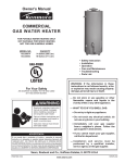
1
Instruction Manual
RESIDENTIAL DIRECT VENT GAS WATER HEATERS
NOT FOR USE IN MANUFACTURED (MOBILE) HOMES
GAMA certification applies to
all residential gas water
heaters with capacities of 20
to 100 gallons with input rating
of 75,000 BTU/Hr. or less.
• For Your Safety •
AN ODORANT IS ADDED TO THE GAS USED
BY THIS WATER HEATER.
ALL TECHNICAL AND WARRANTY QUESTIONS: SHOULD BE DIRECTED TO THE LOCAL DEALER FROM WHOM THE WATER HEATER WAS
PURCHASED. IF YOU ARE UNSUCCESSFUL, PLEASE WRITE TO THE COMPANY LISTED ON THE RATING PLATE ON THE WATER HEATER.
PRINTED 1005
KEEP THIS MANUAL IN THE POCKET ON HEATER FOR FUTURE REFERENCE
WHENEVER MAINTENANCE ADJUSTMENT OR SERVICE IS REQUIRED.
1
183774-001
SAFE INSTALLATION, USE AND SERVICE
Your safety and the safety of others is extremely important in the installation, use and servicing of this water heater.
Many safety-related messages and instructions have been provided in this manual and on your own water heater to warn you and
others of a potential injury hazard. Read and obey all safety messages and instructions throughout this manual. It is very
important that the meaning of each safety message is understood by you and others who install, use or service this water heater.
All safety messages will generally tell you about the type of hazard, what can happen if you do not follow the safety message and
how to avoid the risk of injury.
IMPORTANT DEFINITIONS
• Qualified Installer: A qualified installer must have ability equivalent to a licensed tradesman in the fields of plumbing,
air supply, venting and gas supply, including a thorough understanding of the requirements of the National Fuel Gas
Code as it relates to the installation of gas fired water heaters. The qualified installer must also be familiar with the
design features and use of flammable vapor ignition resistant water heaters, and have a thorough understanding of this
instruction manual.
• Service Agency: A service agency also must have ability equivalent to a licensed tradesman in the fields of plumbing,
air supply, venting and gas supply, including a thorough understanding of the requirements of the National Fuel Gas
Code as it relates to the installation of gas fired water heaters. The service agency must also have a thorough
understanding of this instruction manual, and be able to perform repairs strictly in accordance with the service guidelines
provided by the manufacturer.
• Gas Supplier: The Natural Gas or Propane Utility or service who supplies gas for utilization by the gas burning
appliances within this application. The gas supplier typically has responsibility for the inspection and code approval of
gas piping up to and including the Natural Gas meter or Propane storage tank of a building. Many gas suppliers also
offer service and inspection of appliances within the building.
• Piezo-Electric Spark Gas Ignition System: A combination of a piezo-electric spark generator, high voltage lead(s) and
a spark electrode(s) designed to ignite pilot burner gas at an appliance burner.
2
GENERAL SAFETY
3
TABLE OF CONTENTS
SAFE INSTALLATION, USE AND SERVICE ............................... 2
GENERAL SAFETY .................................................................. 3
TABLE OF CONTENTS .............................................................. 4
INTRODUCTION ........................................................................ 4
Preparing for the New Installation ................................... 4
TYPICAL INSTALLATION ...................................................... 5-6
LOCATING THE NEW WATER HEATER ..................................... 7
Facts to Consider About Location ............................... 7-8
Venting Clearances .......................................................... 8
Optional Wire Grill ............................................................ 9
Flue Extensions ................................................................ 9
Vertical Height (Extension Kit) ....................................... 10
Horizontal (Extension Kit) .............................................. 10
Vent Installations ....................................................... 11-24
INSTALLING THE NEW WATER HEATER ................................ 25
Water Piping ................................................................... 25
Temperature-Pressure Relief Valve ............................... 26
Filling the Water Heater .................................................. 27
Gas Piping ................................................................ 27-28
Sediment Traps .............................................................. 28
Installation Checklist ....................................................... 29
LIGHTING & OPERATING LABEL ............................................ 30
TEMPERATURE REGULATION ................................................ 31
FOR YOUR INFORMATION ..................................................... 31
Start Up Conditions ........................................................ 31
Condensate .................................................................... 32
Smoke/Odor .................................................................... 32
Thermal Expansion ......................................................... 32
Strange Sounds .............................................................. 32
OPERATIONAL CONDITIONS .................................................. 32
Smelly Water .................................................................. 32
“Air” in Hot Water Faucets ............................................. 32
High Temperature Shut Off System ............................... 32
PERIODIC MAINTENANCE ....................................................... 33
Venting System Inspection ............................................ 33
Burner Inspection ........................................................... 33
Burner Cleaning .............................................................. 33
Housekeeping ................................................................ 34
Anode Rod Inspection .................................................... 34
Temperature-Pressure Relief Valve Operation .............. 34
Draining .......................................................................... 34
Drain Valve Washer Replacement ................................. 35
LEAKAGE CHECKPOINTS ...................................................... 35
REPAIR PARTS ....................................................................... 36
TROUBLESHOOTING .............................................................. 40
NOTES .............................................................................. 41-43
WARRANTY ..................................................................... Insert
INTRODUCTION
Thank You for purchasing this water heater. Properly installed and
maintained, it should give you years of trouble free service.
2. The installation must conform with these instructions and the local
code authority having jurisdiction. In the absence of local codes,
installations shall comply with the National Fuel Gas Code ANSI
Z223.1/NFPA 54. This publication is available from the Canadian
Standards Association, 8501 East Pleasant Valley Rd., Cleveland
Ohio 44131, or The National Fire Protection Association, 1
Batterymarch Park, Quincy, MA 02269.
Abbreviations Found In This Instruction Manual:
• CSA - Canadian Standards Association
• ANSI - American National Standards Institute
• NFPA - National Fire Protection Association
• ASME - American Society of Mechanical Engineers
• GAMA - Gas Appliance Manufacturer’s Association
3. If after reading this manual you have any questions or do not
understand any portion of the instructions, call the local gas utility or
the manufacturer whose name appears on the rating plate.
This gas-fired water heater is design certified by CSA INTERNATIONAL
under American National Standard/CSA Standard for Gas Water Heaters
ANSI Z21.10.1 • CSA 4.1 (current edition).
4. Carefully plan the place where you are going to put the water heater.
Correct combustion, vent action and vent pipe installation are very
important in preventing death from possible carbon monoxide
poisoning and fires, see Figures 1 and 2.
This gas-fired water heater is equipped with a piezo-electric spark
device used for pilot burner ignition, and complies with the Standard for
Manually-Operated Piezo-Electric Spark Gas Ignition Systems and
Components, ANSI Z21.77 • CGA 6.23.
Examine the location to ensure the water heater complies with the
“Locating the New Water Heater” section in this manual.
PREPARING FOR THE INSTALLATION
5. For California installation this water heater must be braced, anchored
or strapped to avoid falling or moving during an earthquake. See
instructions for correct installation procedures. Instructions may be
obtained from California Office of the State Architect, 400 P Street,
Sacramento, CA 95814.
1. Read the “General Safety” section, page 3 of this manual first and
then the entire manual carefully. If you don’t follow the safety rules,
the water heater will not operate properly. It could cause DEATH,
SERIOUS BODILY INJURYAND/OR PROPERTY DAMAGE.
This manual contains instructions for the installation, operation, and
maintenance of the gas-fired water heater. It also contains warnings
throughout the manual that you must read and be aware of. All
warnings and all instructions are essential to the proper operation
of the water heater and your safety. Since we cannot put everything
on the first few pages, READ THE ENTIRE MANUAL BEFORE
ATTEMPTING TO INSTALL OR OPERATE THE WATER HEATER.
6. Massachusetts Code requires this water heater to be installed in
accordance with Massachusetts 248-CMR 2.00: State Plumbing Code
and 248-CMR 5.00.
7. Complies with SCAQMD rule #1121 and districts having equivalent
NOx requirements.
4
TYPICAL INSTALLATION
GET TO KNOW YOUR WATER HEATER - GAS MODELS
A
B
C
D
E
F
G
H
Vent Assembly
Flue Outlet
Anode
Hot Water Outlet
Outlet
Insulation
Gas Supply
Manual Gas Shut-off Valve
I
J
K
L
M
N
O
Ground Joint Union
Drip Leg (Sediment Trap)
Inner Door
Outer Doors with Gaskets
Union
Inlet Water Shut-off Valve
Cold Water Inlet
P
Q
R
S
T
U
V
W
X
Y
Z
Inlet Dip Tube
Temperature-Pressure Relief Valve
Rating Plate
Flue Baffle
Thermostat
Drain Valve
Pilot and Main Burner
Flue
Drain Pan
Piezo Ignitor
Thermostat Shield (optional)
* INSTALL IN ACCORDANCE
WITH LOCAL CODES.
(V) PILOT & MAIN BURNER
* DRIP LEG AS REQUIRED
BY LOCAL CODES.
(T) THERMOSTAT
* ALL PIPING MATERIALS TO BE
SUPPLIED BY CUSTOMERS.
FIGURE 1.
5
TYPICAL INSTALLATION
MIXING VALVE USAGE
FIGURE 2.
HOT WATER CAN SCALD:
This appliance has been design certified as complying withAmerican National
Standard/CSA Standard for water heaters and is considered suitable for:
Water heaters are intended to produce hot water. Water heated
to a temperature which will satisfy space heating, clothes
washing, dish washing, and other sanitizing needs can scald
and permanently injure you upon contact. Some people are
more likely to be permanently injured by hot water than others.
These include the elderly, children, the infirm or physically/
mentally handicapped. If anyone using hot water in your home
fits into one of these groups or if there is a local code or state
law requiring a certain temperature water at the hot water tap,
then you must take special precautions. In addition to using
the lowest possible temperature setting that satisfies your
hot water needs, a means such as a *Mixing Valve shall be
used at the hot water taps used by these people or at the
water heater. Mixing valves are available at plumbing supply
or hardware stores. Consult a Qualified Installer or Service
Agency. Follow mixing valve manufacturer’s instructions for
installation of the valves. Before changing the factory setting
on the thermostat, read the “Temperature Regulation” section
in this manual, see Figures 109 and 110.
Water (Potable) Heating: All models are “considered suitable for
water (potable) heating.”
Water (Potable) Heating and Space Heating: Certain models are
“considered suitable for water (potable) heating and space heating.”
Refer to the model and rating plate of the water heater.
6
LOCATING THE NEW WATER HEATER
FACTS TO CONSIDER ABOUT THE LOCATION
Carefully choose an indoor location for the new water heater, because
the placement is a very important consideration for the safety of the
occupants in the building and for the most economical use of the
appliance. This water heater is not for use in manufactured
(mobile) homes or outdoor installation.
Whether replacing an old water heater or putting the water heater in a
new location, the following critical points must be observed:
1. The location selected should be indoors, as close as practical to the
outside wall through which the water heater vent is going to be
installed, and as centralized with the water piping system as possible.
The water heater, as all water heaters, will eventually leak. Do not
install without adequate drainage provisions where water flow will
cause damage.
2. Selected location must provide adequate clearances for servicing
and proper operation of the water heater.
INSTALLATIONS IN AREAS WHERE FLAMMABLE LIQUIDS (VAPORS)
ARE LIKELY TO BE PRESENT OR STORED (GARAGES, STORAGE AND
UTILITY AREAS, ETC.): Flammable liquids (such as gasoline, solvents,
propane [LP or butane, etc.] and other substances such as adhesives,
etc.) emit flammable vapors which can be ignited by a gas water heater’s
pilot light or main burner. The resulting flashback and fire can cause
death or serious burns to anyone in the area, as well as property damage.
If installation in such areas is your only option, then the installation must
be accomplished in a way that the pilot flame and main burner flame are
elevated from the floor at least 18 inches (45.7 cm). While this may
reduce the chances of flammable vapors, from a floor spill being ignited,
gasoline and other flammable substances should never be stored or
used in the same room or area containing a gas water heater or other
open flame or spark producing appliance. NOTE: Flammable vapors may
be drawn by air currents from other areas of the structure to the appliance.
Installation of the water heater must be accomplished in such a manner
that if the tank or any connections should leak, the flow will not cause
damage to the structure. For this reason, it is not advisable to install the
water heater in an attic or upper floor. When such locations cannot be
avoided, a suitable drain pan should be installed under the water heater.
Drain pans are available at your local hardware store. Such a drain
pan must have a minimum length and width of at least 2 inches (5.1 cm)
greater that the water heater dimensions and must be piped to an
adequate drain. Drain pan depth must allow for access to the outer
doors for servicing the pilot and burner.
Water heater life depends upon water quality, water pressure and
the environment in which the water heater is installed. Water heaters
are sometimes installed in locations where leakage may result in
property damage, even with the use of a drain pan piped to a drain.
However, unanticipated damage can be reduced or prevented by a
leak detector or water shut-off device used in conjunction with a
piped drain pan. These devices are available from some plumbing
supply wholesalers and retailers, and detect and react to leakage in
various ways:
• Sensors mounted in the drain pan that trigger an alarm or turn off the
incoming water to the water heater when leakage is detected.
• Sensors mounted in the drain pan that turn off the water supply to
the entire home when water is detected in the drain pan.
• Water supply shut-off devices that activate based on the water
pressure differential between the cold water and hot water pipes
connected to the water heater.
• Devices that will turn off the gas supply to a gas water heater while
at the same time shutting off its water supply.
7
No vent damper, whether it is operated thermally or otherwise, is to
be installed on this direct vent water heater. Alteration of any part
of the factory-furnished vent assembly could result in improper
operation due to restriction of flue gases and may cause carbon
monoxide poisoning.
Also, the water heater must be located and/or protected so it is not
subject to physical damage by a moving vehicle.
This water heater must not be installed directly on carpeting. Carpeting
must be protected by metal or wood panel beneath the appliance
extending beyond the full width and depth of the appliance by
at least 3 inches (7.62 cm) in any direction, or if the appliance
is installed in an alcove or closet, the entire floor must be
covered by the panel. Failure to heed this warning may result in a
fire hazard.
Venting Clearances
Minimum clearances between the water heater and combustible and
noncombustible construction are 0 inch at the sides, 0 inches from
back, 4”(10.2 cm) from front of jacket to closet door and 3”(7.6 cm)
from top of jacket to combustible and noncombustible material. Minimum
vent clearance: 0 inches.
When determining the installation location for a direct vent water heater,
snow accumulation and drifting should be considered in areas where
applicable. See Figures 4 through 8 and items below.
• 18” minimum in all directions from any obstruction that may interfere.
• 18” minimum from the ground and 12 “ from ceiling overhangs.
• The direct vent terminal shall terminate at least 3 feet above any
forced air inlet located within 10 feet. See Figure 5.
• 9” minimum horizontally from or above any door, window or gravity
air inlet into the building (50,000 BtuH input or less.)
• 12” minimum horizontally from or above any door, window or gravity
air inlet into the building (over 50,000 BtuH input).
• 12” minimum below any door, window or gravity air inlet into the
building (50,000 BtuH input or less).
• 18” minimum below any door, window or gravity air inlet into the
building (over 50,000 BtuH input).
• 18” minimum from other gravity or natural appliance outlet vents
when directly above or 135° to either side of center line. See Figure 6.
• 36” minimum from any outlet vents when directly below or 45° to
either side of center line. See Figure 7.
FIGURE 3.
• 36” minimum in all directions from any other forced air appliance
outlet vent. See Figure 7.
NOTE: Provide 24 inches (61 cm) front clearance for servicing and
a adequate clearance between the jacket top and ceiling for servicing
the flue area.
• The location selection must provide clearances for servicing and
proper operation of the water heater. See Figure 8.
• Vent termination must not be within 4 feet of any items such as gas
meters, gas valves or other gas regulating equipment.
Combustion Air and Ventilation
• Unless specified at time of ordering, a standard extension
kit (No. 9000687) is individually packaged and shipped with
the water heater.
FIGURE 4.
8
Some local codes may require a vent cap cover. Figure 9 shows the
optional wire vent cap protector available from the water heater
manufacturer.
A wire mesh chain link fence (see Figure 9) may be used instead of the
factory cover. Care should be taken to maintain adequate ventilation
around the vent cap. If a chain link fence is installed, it must not be used
as a storage area for items that may block proper ventilation.
FIGURE 5.
FIGURE 9.
Flue Extensions
There are three optional extension kits available. Any combination of
the three kits can be chosen; however, only one kit can be used
vertically and/or horizontally, see Figures 10 & 11.
Unless otherwise specified at the time of ordering, a standard extension kit (9000687) is individually packaged and shipped within the water
heater carton.
FIGURE 10.
FIGURE 8.
Optional Wire Grill
When the water heater vent cap is low enough to be touched
accidentally, or is accessible to small children, installation of a
protective vent cover is recommended. See Figure 9.
9
Vertical Height (Extension Kit)
BTU’s
DIMENSION “F” (IN CENTIMETERS)
*Gal. in 1000’s 9000687
Cap. Nat/L.P
40 36/36
50 38/38
40 40/40
50 48/44
75 55 NAT.
9001246
9001247
9001248
STD.
MIN.
MAX.
MIN.
MAX.
MIN.
MAX.
162
183
162
193
194
183
205
183
214
215
196
218
196
228
227
196
219
196
228
227
224
247
224
256
255
224
247
224
256
255
279
302
279
312
311
*Check the model and rating plate attached to the water heater for
specific model number and other detailed information.
Horizontal (Extension Kit)
To determine the horizontal length and extension kit needed, simply
plug the dimensions “D” and “G” into the equation below. The answer
“E” should then be located in Chart #2. The size range in which “E”
dimension falls indicates the kit that should be used horizontally to
obtain the desired length.
It is simple to determine which kit is needed for vertical height. Take the
total height (to the top of the flue) required and comparing that to “F
dimension” in the chart #1, it can be determined which kit needs to be
used vertically.
“D” = The wall thickness
“G” = The distance wanted between the edge of the water heater
and the inside edge of the wall
“E” = The distance the extension kit must be able to extend
The Equation: D + G = E
FIGURE 11.
FIGURE 13 .
CHART #2.
DIMENSION “E” (IN INCHES)
40-50 GAL.
VENT KITS
9000687-Std.
9001246
9001247
9001248
MIN
75 GAL.
MAX
3 1/2
10
15 1/2
26 1/2
10
15 1/2
26 1/2
48
MIN
MAX
7/8
7 3/8
12 7/8
23 7/8
7 3/8
12 7/8
23 7/8
45 3/8
DIMENSION “E” (IN CENTIMETERS)
40-50 GAL.
VENT KITS
9000687-Std.
9001246
9001247
9001248
FIGURE 12.
CHART #1.
BTU’s
*Gal. in 1000’s
Cap. Nat/L.P
40 36/36
50 38/38
40 40/40
50 48/44
75 55 NAT.
DIMENSION “F” (IN INCHES)
9000687
STD.
9001246
MIN.
MAX.
9001247
MIN.
MAX.
BTU’s
9001248
MIN.
MIN
8.9 cm
25.4 cm
39.4 cm
67.3 cm
75 GAL.
MAX
MIN
25.4 cm
29.4 cm
67.3 cm
121.9 cm
2.2 cm
18.7 cm
32.7 cm
60.6 cm
MAX
18.7 cm
32.7 cm
60.6 cm
115.3 cm
DIMENSION “A, B, C” ( INCHES /CENTIMETERS )
*Gal. in 1000’s
MAX.
Cap.
63 3/4 72
77
77
88
88
110
72
80 3/4 86 86 1/4 97 1/4 97 1/4 118 3/4
63 3/4 72
77
77
88
88
110
76
84 1/4 89 3/4 89 3/4 100 3/4 100 3/4 122 3/4
76 1/4 84 1/2 89 1/2 89 1/2 100 1/2 100 1/2 122 1/2
Nat.
40 36/36 48 3/4”
50 38/38 57 1/2”
40 40/40 48 3/4”
50 48/44
61”
75 55 NAT.
63”
10
A
124 cm
146 cm
124 cm
155 cm
160 cm
B
41 3/4”
50 1/2”
41 3/4”
54”
54 3/4”
C
106 cm
21”
128 cm
21”
106 cm
21”
137 cm
21”
139 cm 26 1/4”
53 cm
53 cm
53 cm
53 cm
67 cm
ALL INSTALLATIONS
Standard Vent Kit - Installation #1
For ease of assembly the installation of the various kit combinations
has been broken into individual sections. The two steps below are
common to all installations. Once these have been performed, you
need only to refer to the type installation that pertains to you.
The opening through the wall should be cut at this time. If this has not
been done, refer to “Cutting The Opening Through The Outside Wall ”
section.
Installation Using Vent Kits:
1. Standard Vent Kit 9000687 .............................................
2. Optional Vertical Vent Kit .................................................
with Standard Vent Kit
3. Optional Horizontal Vent Kit .............................................
4. Optional Horizontal ..........................................................
and Vertical Vent Kits
Page 11
Page 14
Page 17
Page 19
Cutting The Opening Through The Outside Wall
After thoroughly reading the “Locating the New Water Heater”
section of this manual and you have chosen a suitable water
heater installation site, use Chart #1 to determine dimensions for
the wall opening.
1. Lock the elbow to the straight 3” (76 mm) flue pipe. Set this assembly
in place on the end of the water heater’s flue collar.
Cut a 6 1/4” (159 mm) diameter hole completely through the outside
wall.
FIGURE 15.
2. Mark the flue collar at the slots in the elbow. Using a #22 drill bit, drill
holes into the flue collar at the two slots and secure the elbow to the
flue collar using the screws provided.
FIGURE 14.
NOTE: Make sure elbow is properly aligned to opening in the
outside wall.
Water Heater Attitude
There is a certain amount of variance with regard to the direction the
water heater faces.
Standing in front of the water heater (gas control facing you), set the
3” (76 mm) diameter elbow (slotted end) on the flue. This will give you
a better understanding of the relation of the vent assembly to the
opening in the wall and more importantly any possibility of interference
of venting and water piping.
The direction of the water heater can now be made. Also consider the
gas control valve to insure installation, lighting and maintenance
accessibility are retained.
FIGURE 16 .
3. Using the tube of sealant supplied, run an ample amount around the
oval flare of the jacket.
NOTE: Supplementary installation instructions are applicable only if
this direct vent water heater is provided with the alternate brown
porcelain-enameled vent cap and the 6” (152 mm) vent wall assembly
show below, See pages 22 thru 24.
FIGURE 17.
11
4. First remove the 3” (76 mm) horizontal extension from the elbow. Starting with the long end (with four securing holes), place the 6” (152 mm)
diameter vent elbow over the 3” (76 mm) diameter elbow. Bend the
round end “oval” to fit the flared oval end of the jacket top.
FIGURE 21.
8. Slide the vent collar (to be installed later) over the 6” (152 mm) vent
elbow.
FIGURE 18.
5. Making sure the 6” (152 mm) diameter elbow is centered around the 3”
(76 mm) diameter flue, secure the 6” (152 mm) diameter vent pipe
using four sheet metal screws at the connection of the jacket top.
FIGURE 22.
9. Place the water heater at the opening in the wall, at the predetermined
clearance.
FIGURE 19 .
6. The standard vent kit includes a 6” (152 mm) diameter extension pipe
which is used when “E” dimension is over 6 1/2” (165 mm).
FIGURE 23.
10. Move outdoors with all the remaining vent parts. Using the tube of
sealant supplied, run an ample amount on the inside surface of the
collar assembly that will contact the exterior wall and also fill the
bead on the end of the 6” ((152 mm) diameter vent collar.
FIGURE 20.
7. If “E” dimension is less than 6 1/2” (165 mm) move to next step.
If “E” dimension is over 6 1/2” (165 mm), assemble the 6” (152 mm)
diameter extension pipe (crimped end) to the 6” (152 mm) diameter vent
elbow and secure using two sheet metal screws. Apply an ample amount
of sealant around the joint to ensure a good seal.
FIGURE 24.
12
15. The vent cap has four holes around the outer edge. Remove the four
screws used to temporarily attach the collar to the exterior wall.
Then secure the vent cap assembly with the vent collar assembly to
the exterior wall using the same four screws.
11. Install the vent collar assembly through the wall, connecting it to the
extension and/or elbow (depending on which one was used).
NOTE: Screws are supplied: However, substitution may be
necessary depending on the exterior wall material.
FIGURE 25.
12. We have supplied four wood screws to temporarily attach the collar
to the exterior wall of the building. However, other types of screws
may have to be substituted depending on the material used in the
construction of the exterior wall.
FIGURE28.
16. Go back indoors to attach inside collar to the inside wall. Place the collar
against the wall. Secure to wall by using four long sheet metal screws.
FIGURE 26.
NOTE: Screws are supplied: However, substitution may be
necessary depending on the interior wall material.
13. Insert the 3” (76 mm) diameter flue extension pipe into the vent collar
assembly (flared & notched end first) and lock (turn clockwise to
lock studs to slots) the flue extension pipe to the flue elbow.
FIGURE 29.
17. Using the tube of sealant supplied, run an ample amount of sealant
around the edge of the vent pipe where it is inserted through the
inside collar to seal air drafts from wall.
14. Connect the vent cap by sliding its end over the 3” (76 mm) diameter
extension pipe and O-ring.
NOTE: To facilitate ease of assembly of the vent cap to the 3” (76 mm)
pipe, a soap solution can be applied to the O-ring gasket.
FIGURE 27.
FIGURE 30.
13
2. Set the vertical 3” (76 mm) diameter telescoping flue section in place
on the flue collar. Using a # 22 drill bit, drill two holes (180° apart) and
secure the vertical assembly to the flue collar.
Optional Vertical Vent Kit with Standard Horizontal
Vent Kit - Installation #2
Any Optional Vent Kit
FIGURE 33.
3. Slide the 6” (152 mm) vent telescoping section apart to reveal the
beads. Using the caulking supplied, fill the beads.
*Each part is stamped with a part number.
The opening through the wall should be cut at this time. If this has not been
done, refer to “Cutting The Opening Through The Outside Wall,” on page 11.
1. First it must be determined how far the vertical 3” (76 mm) diameter
telescoping flue sections are set and locked together using the two
screws supplied.
FIGURE34.
4. Apply an ample amount of sealant around the oval flare of the jacket.
FIGURE 31 .
Use chart #3, drawing and simple equation below, to find the length of
expansion of the telescoping flue sections. Because of manufacturing
tolerances, place the telescoping extension on the water heater and
adjust the height (“X” Dimension) and mark the point. Once the length has
been determined, lock the two sections together by drilling two holes
(180° apart) in the pipe and securing with the screws supplied.
FIGURE 35.
5. Place the 6” (152 mm) vent section over the 3” (76 mm) flue section.
Subtract 3/4” (19 mm) from the predetermined “X” dimension. This
determines the length of the 6” (152 mm) vent extension. Slide the 6”
(152 mm) vent extension apart to this dimension and secure with the
two screws supplied.
FIGURE 36.
6. Form the round end of the 6” (152 mm) vent extension to the top of the
jacket and secure with four sheet metal screws.
FIGURE 32.
CHART #3
*GAL CAP.
40
50
40
50
75
*BTU’s in 1000’s - NAT./L.P.
36/36
38/38
40/40
48/44
55 NAT.
A
48 3/4”
57 1/2”
48 3/4”
61”
63”
124 cm
146 cm
124 cm
155 cm
160 cm
*Check the model and rating plate attached to the water heater for
specific model number and other detailed information.
FIGURE 37.
14
10. If “E” dimension is less than 6 1/2” (165 mm) move to next step. If “E”
dimension is over 6 1/2” (165 mm), assemble the 6” (152 mm) diameter
extension pipe to the 6” (152 mm) diameter vent elbow and secure
using two sheet metal screws. Using the tube of sealant supplied,
run an ample amount around the joint to insure a good seal.
7. Place the 3” (76 mm) elbow on the flue extension.
NOTE: Make sure elbow is properly aligned to opening in
the outside wall.
Mark the 3” (76 mm) diameter end of the flue extension at the slots
in the elbow. Using a #22 drill bit, drill holes into the flue extension
at the two slots and secure the elbow to the flue extension using
the screws provided.
FIGURE 41.
11. Slide the vent collar (to be installed later) over the 6” (152 mm) vent elbow.
FIGURE 38.
8. Be sure the 6” (152 mm) diameter elbow is centered around the 3”
(76 mm) diameter flue. Secure the 6” (152 mm) diameter vent pipe
using two sheet metal screws at the cnnection of the elbow and
6” (152 mm) vertical extension.
FIGURE 42.
12. Move the water heater into position at the vent opening.
FIGURE 39.
9. The standard vent kit includes a 6” (152 mm) diameter extension
pipe which is used when dimension “E” (refer to Chart 2) is over
6 1/2” (165 mm).
FIGURE43.
13. Take the remaining vent parts outside to complete the installation.
Using the tube of sealant supplied, apply an ample amount of sealant
to the inside surface of the collar assembly that will contact the
exterior wall. Also, apply sealant to the bead around the outside
edge at the end of the 6” (152 mm) diameter vent collar.
FIGURE 40.
FIGURE 44.
15
14. Install the vent collar assembly through the wall, connecting it to the
extension and /or elbow depending on which one was used.
18. The vent cap has four holes around the outer edge. Remove the four
screws used to temporarily attach the collar to the exterior wall. Then
secure the vent cap to the exterior wall using the same four screws.
NOTE: Screws are supplied. However, substitution may be
necessary depending on the exterior wall material.
FIGURE 45.
15. Four wood screws are supplied to temporarily attach the collar to the
exterior wall of the building. However, other types of screws may
have to be substituted depending on the construction material of the
exterior wall.
FIGURE 49.
19. Go back indoors to attach inside collar to the inside wall. Place the collar
against the wall. Secure to wall by using four long sheet metal screws.
NOTE: Screws are supplied. However, substitution may be
necessary depending on the exterior wall material.
FIGURE46.
16. Insert the 3” (76 mm) diameter flue extension pipe into the vent collar
assembly (flared and notched end first) and rotate clockwise to lock
the studs to the slots in the extension pipe.
FIGURE 50.
FIGURE 47.
20. Using the tube of sealant supplied, apply an ample amount of sealant
around the edge of the vent pipe where it is inserted through the
inside collar. This will seal air draft from the walls.
17. Connect the vent cap by sliding it’s end over the 3” (7.6 cm) diameter extension pipe an O-ring.
NOTE: to facilitate ease of assembly of the vent cap to the 3”
(7.6 cm) pipe a soap solution can be applied to the O-ring
gasket.
FIGURE48.
FIGURE 51.
16
Optional Horizontal Vent Kit - Installation #3
FIGURE 54.
4. First remove the 3” (7.6 cm) horizontal extension from the elbow.
Starting with the long end, which has four mounting holes, place the 6”
(152 mm) diameter vent elbow over the 3” (76 mm) elbow. Bend the
round end to fit the flared oval end of the jacket top.
If the vent hole has not been cut, refer to “Cutting The Opening
Through The Outside Wall.” See page 11.
1. Lock the elbow to the straight 3” (76 mm) flue pipe. Set this assembly
in place on the end of the water heater’s flue collar.
FIGURE 55.
5. Be sure the 6” (152 mm) diameter elbow is centered around the
3” (76 mm) diameter flue. Secure the vent pipe with four sheet metal
screws at the connection at the jacket top.
FIGURE 52.
FIGURE 56.
2. Mark the flue collar at the slots in the elbow. Using a # 22 drill bit, drill
holes into the collar at the two slots and secure the elbow to the collar
with the screws provided.
NOTE: the standard kit includes a 3” (76 mm) flue extension
and a 6” (152 mm) elbow extension. These parts will not
be used with the horizontal kit.
NOTE: make sure elbow is properly aligned to the opening in
the outside wall.
6. Slide the vent collar (to be installed later) over the 6” (152 mm)
vent elbow.
FIGURE 53.
3. Using the tube of sealant supplied run an ample amount around the
oval flare of the jacket.
FIGURE 57.
17
11. Insert the vent collar assembly through the wall opening, connecting to the 6” (152 mm) telescoping extension. Remember, the vent
extension has not been connected so it may be necessary to go
back outdoors and push it back up into the wall opening for a tight
fit to the collar.
7. Place the waterheater at the opening in the wall at the
predetermined clearance.
FIGURE 62.
12. Four wood screws were supplied to temporarily attach the collar to
the exterior wall of the building. However, you may have to substitute other types of screws depending on the construction material of
the exterior wall.
FIGURE 58.
8. Slide the 6” (152 mm) telescoping vent section apart to expose the
beads. Use the supplied tube of sealant and fill the exposed beads.
FIGURE 63.
13. Insert the vent cap into the vent collar assembly.
FIGURE 59.
9. Insert the 6” (152 mm) telescoping vent section into the opening in
the wall.
FIGURE 64.
14. The vent cap has four holes around the outer edge. Remove the four
screws used to temporarily attach the collar to the exterior wall.
Then secure the vent cap assembly with the vent collar assembly to
the exterior wall using the same screws.
FIGURE 60.
Note: Screws are supplied; however, substitution may be
necessary depending on the exterior wall material.
10. The remaining vent parts will be installed from the outside. Apply ample
amount of sealant to the inside surface of the collar assembly that will
contact the exterior wall. Also, apply sealant to the bead around the
outside edge at the end of the 6” (152 mm) diameter vent collar.
FIGURE 65.
15. The remainder of the installation will be indoors to complete the
assembly process.
FIGURE 61.
18
20. Secure the 6” (15.2 cm) vent extension to the vent elbow with the
two provided screws spacing them 180° apart.
16. Collapse the 6” flue extension assembly as shown below. Install
the O-ring end of the 3” (7.6 cm) extension approximately 1 1/4”
(3.2 cm) into the end of the vent cap. If necessary, apply a soap
solution to the O-ring to ease the assembly. Rotate the 3” extension
clockwise until the other end is locked to the studs on the elbow.
FIGURE 70.
Optional Vertical and Horizontal Vent Kit Installation #4
FIGURE 66.
17. Using a # 22 drill bit, drill holes 180° apart at the connection point of
the two 3” (7.6 cm) flue extensions. Secure with the two screws
provided.
FIGURE 67.
18. Expand the 6” (15.2 cm) telescoping extension to connect at the
vent elbow.
If the vent hole has not been cut, refer to section, “Cutting The Opening
Through The Outside Wall.” See page 11.
1. First determine how far the vertical 3” (7.6 cm) diameter telescoping
flue sections are to be set and locked together with two screws
supplied.
FIGURE 68.
19. Push the vent collar from the elbow against the wall and secure with
the four provided screws.
FIGURE 71.
Use the Chart #4, and figure 72 to determine the length of expansion of
the telescoping flue sections. Because of manufacturing tolerances, put
the telescoping extension on the water heater, adjust the height (dimension “X”) and mark the point. Once the length has been determined, lock
the two sections together by drilling two holes (180° apart) in the pipe
and secure with the supplied screws.
FIGURE 69.
19
5. Place the 6” (15.2 cm) vent section over the 3” (7.6 cm) flue section.
Subtract 3/4” (1.9 cm) from the predetermined “X” dimension. This
determines the length of the 6” (15.2 cm) vent extension. Slide the 6”
(15.2 cm) vent extension apart to this dimension and secure with the
two screws supplied.
FIGURE 72.
CHART #4.
*GAL CAP *BTU’s in 1000’s - NAT./L.P.
A
40
36/36
48 3/4” 124 cm
50
38/38
57 1/2” 146 cm
40
40/40
48 3/4” 124 cm
50
48/44
61”
155 cm
75
55 NAT.
63”
160 cm
*Check the model and rating plate attached to the water heater for
specific model number and other detailed information.
FIGURE 76.
6. Form the round end of the 6” (15.2 cm) vent extension to the top of the
jacket and secure with four sheet metal screws.
2. Set the vertical 3” (7.6 cm) diameter telescoping flue section in place on
the flue collar. Using a #22 drill bit, drill two holes (180° apart) and secure
the vertical assembly to the flue collar with the two supplied screws.
FIGURE 77.
7. Place the 3” (7.6 cm) elbow on the flue extension. Align the elbow to
the hole previously made in the outside wall. Using the slots in the
elbow, mark the 3” (7.6 cm) diameter end of the flue extension. Using
a #22 drill bit, drill two holes into the flue extension and secure with
the two provided sheet metal screws.
FIGURE 73.
3. Slide the 6” (15.2 cm) vent telescoping section apart to reveal the
beads. Fill the beads using the supplied caulking.
FIGURE 74.
FIGURE 78.
4. Apply an ample amount of sealant around the oval flare of the jacket.
NOTE: the standard kit includes a 3” (7.6 cm) flue extension
and a 6” (15.2 cm) elbow extension. These parts will not
be used with the horizontal kit.
FIGURE 75.
20
8. Be sure the 6” (15.2 cm) diameter elbow is centered around the 3”
(7.6 cm) diameter flue, secure using two sheet metal screws at the
connection of the elbow and the 6” (15.2 cm) vertical extension.
11. Slide the 6” (15.2 cm) telescoping vent section apart to expose the
beads. Use the supplied tube of caulking and fill the exposed beads.
FIGURE 82.
12. Insert the 6” (15.2 cm) telescoping vent section into the wall.
FIGURE 79.
9. Slide the vent collar (to be installed later) over the 6” (15.2 cm) vent elbow.
FIGURE 83.
13. The remaining vent parts will be installed from the outside. Apply
ample amount of sealant to the inside surface of the collar assembly
that will contact the exterior wall. Also, apply sealant to the bead
around the outside edge at the end of the 6” (15.2 cm) diameter vent
collar.
FIGURE 80.
10. Move the water heater into position at the vent opening.
FIGURE 84.
14. Install the vent collar assembly through the wall, connecting to the
6” (15.2 cm) telescoping extension. Remember, the extension is not
connected and may be necessary to return indoors to push the
extension back against the interior wall for a tight fit to the collar.
FIGURE 85.
FIGURE 81.
21
15. Four wood screws were supplied to temporarily attach the collar to
the exterior wall of the building. However, you may have to substitute
other types of screws depending on the construction material of the
exterior wall.
20. Using a #22 drill bit, drill holes 180° apart at the connection point of
the two 3” (76 mm) flue extensions. Secure with the two screws
provided.
FIGURE 86.
16. Insert the vent cap into the vent collar assembly.
FIGURE 90.
21. Expand the 6” (152 mm) telescoping extension pipes to connect at
the vent elbow.
FIGURE 87.
17. The vent cap has four holes around the outer edge. Remove the four
screws used to temporarily attach the collar to the exterior wall.
Then secure the vent cap assembly with the vent collar assembly to
the exterior wall using the same screws.
Note: Screws are supplied; however, substitution may be
necessary depending on the exterior wall material.
FIGURE 91.
22. Push the vent collar from the elbow against the wall and secure with
the four provided screws.
FIGURE 88.
18. The remainder of the installation will be conducted indoors to
complete the assembly process.
19. Collapse the 6” extension assembly as shown below. Install the Oring end of the 3” (7.6 cm) extension approximately 11/4” (3.2 cm) into the
end of the vent cap. If necessary, apply a soap solution to the O-ring
to ease the assembly. Rotate the extension clockwise until the other
end is locked to the studs on the elbow.
FIGURE 92.
23. Secure the 6” (152 mm) vent extension to the vent elbow with the
two provided screws spacing them 180° apart.
FIGURE 93.
Optional Vent Cap - Porcelain-Enameled
These supplementary installation instructions are applicable only
if this direct vent water heater is provided with the alternate brown
FIGURE 89.
22
porcelain-enameled vent cap assembly and the 6” (15.2 cm) vent
wall assembly shown by Figure 94.
16. Insert the 3” (7.6 cm) diameter flue extension pipe into the vent collar
assembly (flared and notched end first). Lock the flue extension pipe
to the flue elbow by rotating clockwise to lock studs to slots.
FIGURE 94.
FIGURE 97.
The water heater model designation on the rating plate will have a suffix
“P” to indicate this alternate vent cap assembly.
4. Connect the vent cap by sliding it over the 3” (7.6 cm) diameter
extension pipe and O-ring.
The alternate installation instructions below will replace the itemized
instructions in the manual as follows: Items 11 thru 15 on page 13 and
items 14 thru 18 on page 16.
NOTE: for ease of assembly of the vent cap to the 3” (7.6 cm) pipe a
soap solution can be applied to the O-ring gasket.
1. Making sure the arrow points “UP”, install the vent collar assembly
through the wall, connecting it to the extension and/or elbow
depending on which one was used.
FIGURE 98.
5. The vent cap has six holes around the outer edge. The three larger
ones are to fit over the three screws securing the vent collar assembly to the exterior wall. The three smaller ones will now be used to
attach the vent cap assembly.
FIGURE 95.
2. Three wood screws are supplied to attach the collar to the
exterior wall of the building. However, other types of screws
may have to be substituted depending on the construction of the
exterior wall.
NOTE: screws are supplied. However, substitution may be necessary
depending on the exterior wall material.
NOTE: alternate screws used must not have a head larger than 3/8”
(.95 cm).
The three screws must be placed at every other hole (120° apart) to
secure the vent collar assembly to the outside wall.
FIGURE 99.
FIGURE 96.
23
The following alternate illustrated instructions will replace the
itemized instructions in the manual as follows: Items 11 through
14 on page 18 and Items 14 through 17 on pages 21 and 22.
3. Insert the vent cap in the vent collar assembly.
1. Making sure the arrow points “up”, install the vent collar assembly
through the wall, connecting it to the 6” (15.2 cm) telescoping
extension. Remember, the extension is not connected, and it may be
necessary to return indoors to push the extension back against the
interior wall for a tight fit to the collar.
FIGURE 102.
FIGURE 100.
4. The vent cap has six holes around its outer edge. The three larger
ones are to fit over the three screws securing the vent collar assembly
to the exterior wall. The three smaller ones will now be used to attach
the vent cap assembly.
2. Three wood screws are supplied to attach the collar to the exterior
wall of the building. However, other types of screws may be substituted
depending on the construction of the exterior wall.
NOTE: screws are supplied. However, substitution may be necessary,
depending on the exterior wall material.
NOTE: alternate screws used must not have heads larger than 3/8” (.95 cm).
The three screws must be placed at every other hole 120° apart to
secure the vent collar assembly to the outside wall.
FIGURE 103.
FIGURE 101.
24
INSTALLING THE NEW WATER HEATER
WATER PIPING
As water is heated, it expands (thermal expansion) and closed systems
do not allow for the expansion of heated water.
The water within the water heater tank expands as it is heated and
increases the pressure of the water system. If the relieving point of the
water heater’s temperature-pressure relief valve is reached, the valve
will relieve the excess pressure. The temperature-pressure relief
valve is not intended for the constant relief of thermal
expansion. This is an unacceptable condition and must be corrected.
It is recommended that any devices installed which could create a closed
system have a by-pass and/or the system have an expansion tank to
relieve the pressure built by thermal expansion in the water system.
Expansion tanks are available for ordering through a local plumbing
contractor. Contact the local water supplier and/or a service agency for
assistance in controlling these situations.
NOTE: To protect against untimely corrosion of hot and cold
water fittings, it is strongly recommended that di-electric unions
or couplings be installed on this water heater when connected
to copper pipe.
HOTTER WATER CAN SCALD:
Water heaters are intended to produce hot water. Water heated to a
temperature which will satisfy space heating, clothes washing, dish
washing, cleaning and other sanitizing needs can scald and permanently
injure you upon contact. Some people are more likely to be permanently
injured by hot water than others. These include the elderly, children, the
infirm, or physically/mentally handicapped. If anyone using hot water in
your home fits into one of these groups or if there is a local code or state
law requiring a certain temperature water at the hot water tap, then you
must take special precautions. In addition to using the lowest possible
temperature setting that satisfies your hot water needs, a means such
as a *mixing valve, shall be used at the hot water taps used by these
people or at the water heater, see Figure. Valves for reducing point of
use temperature by mixing cold and hot water are also available. Consult
a Qualified Installer or Service Agency. Follow manufacturer’s instructions
for installation of the valves. Before changing the factory setting on the
thermostat, read the “Temperature Regulation” section in this manual.
This water heater shall not be connected to any heating systems or
component(s) used with a non-potable water heating appliance.
All piping components connected to this unit for space heating applications
shall be suitable for use with potable water.
Toxic chemicals, such as those used for boiler treatment shall not be
introduced into this system.
When the system requires water for space heating at temperatures
higher than required for domestic water purposes, a tempering valve
must be installed. Please refer to Figure 2 for suggested piping
arrangement.
Water supply systems may, because of such events as high line
pressure, frequent cut-offs, the effects of water hammer among others,
have installed devices such as pressure reducing valves, check valves,
back flow preventers, etc. to control these types of problems. When
these devices are not equipped with an internal by-pass, and no other
measures are taken, the devices cause the water system to be closed.
FIGURE 104.
25
Figure 104 shows the typical attachment of the water piping to the
water heater. The water heater is equipped with 3/4 inch NPT water
connections.
The valve must be marked with a maximum set pressure not to exceed
the marked hydrostatic working pressure of the water heater
(150 psi = 1,035 kPa) and a discharge capacity not less than the water
heater input rate as shown on the model rating plate.
NOTE: If using copper tubing, solder tubing to an adapter before
attaching the adapter to the cold water inlet connection. Do
not solder the cold water supply line directly to the cold water
inlet. It will harm the dip tube and damage the tank.
For safe operation of the water heater, the relief valve must not be
removed from its designated opening nor plugged.
The temperature-pressure relief valve must be installed directly into the
fitting of the water heater designed for the relief valve. Position the
valve downward and provide tubing so that any discharge will exit only
within 6 inches (153 mm) above, or at any distance below the structural
floor. Be certain that no contact is made with any live electrical part. The
discharge opening must not be blocked or reduced in size under any
circumstances. Excessive length, over 30 feet (9.14 m), or use of more
than four elbows can cause restriction and reduce the discharge
capacity of the valve, see Figure 106.
T & P Valve and Pipe Insulation
Remove insulation for T & P valve and pipe connections from carton.
No valve or other obstruction is to be placed between the relief valve
and the tank. Do not connect tubing directly to discharge drain unless a 6
inch air gap is provided. To prevent bodily injury, hazard to life, or property
damage, the relief valve must be allowed to discharge water in quantities
should circumstances demand. If the discharge pipe is not connected to a
drain or other suitable means, the water flow may cause property damage.
FIGURE 105.
Fit pipe insulation over the incoming cold water line and the hot water
line. Make sure that the insulation is against the top cover of the heater.
Fit T & P valve insulation over valve. Make sure that the insulation does
not interfere with the lever of the T & P valve.
Secure all insulation using tape.
The Discharge Pipe:
TEMPERATURE-PRESSURE RELIEF VALVE
• Shall not be smaller in size than the outlet pipe size of the valve, or
have any reducing couplings or other restrictions.
• Shall not be plugged or blocked.
• Shall be of material listed for hot water distribution.
• Shall be installed so as to allow complete drainage of both the
temperature-pressure relief valve, and the discharge pipe.
• Shall terminate at an adequate drain.
• Shall not have any valve between the relief valve and tank.
This heater is provided with a properly certified combination
temperature - pressure relief valve by the manufacturer.
The valve is certified by a nationally recognized testing laboratory that
maintains periodic inspection of production of listed equipment of
materials as meeting the requirements for Relief Valves and Automatic
Gas Shut-off Devices for Hot Water Supply Systems, ANSI Z21.22 •
CSA 4.4, and the code requirements of ASME.
The temperature-pressure relief valve must be manually operated at least
once a year. Caution should be taken to ensure that (1) no one is in front
of or around the outlet of the temperature-pressure relief valve discharge
line, and (2) the water manually discharged will not cause any bodily
injury or property damage because the water may be extremely hot.
If replaced, the valve must meet the requirements of local codes, but
not less than a combination temperature and pressure relief valve
certified as indicated in the above paragraph.
26
If after manually operating the valve, it fails to completely reset and
continues to release water, immediately close the cold water inlet to the
water heater, follow the draining instructions, and replace the
temperature-pressure relief valve with a new one.
GAS PIPING
Make sure the gas supplied is the same type listed on the model rating
plate. The inlet gas pressure must not exceed 14 inch water column (2.6 kPa)
for natural and propane gas (L.P.). The minimum inlet gas pressure
shown on the rating plate is that which will permit firing at rated input.
If the gas control valve is subjected to pressures exceeding 1/2 pound
per square inch (3.5 kPa), the damage to the gas control valve could
result in a fire or explosion from leaking gas.
If the main gas line Shut-off serving all gas appliances is used, also turn
“off” the gas at each appliance. Leave all gas appliances shut “off” until
the water heater installation is complete.
FIGURE 106.
A gas line of sufficient size must be run to the water heater. Consult the
current edition of National Fuel Gas Code ANSI Z223.1/NFPA 54 and your
gas supplier concerning pipe size.
FILLING THE WATER HEATER
There must be:
• A readily accessible manual shut off valve in the gas supply line serving
the water heater, and
• A drip leg (sediment trap) ahead of the gas control valve to help prevent
dirt and foreign materials from entering the gas control valve.
• A flexible gas connector or a ground joint union between the shut off
valve and control valve to permit servicing of the unit.
Be sure to check all the gas piping for leaks before lighting the water
heater. Use a soapy water solution, not a match or open flame. Rinse
off soapy solution and wipe dry.
Never use this water heater unless it is completely full of water. To
prevent damage to the tank, the tank must be filled with water. Water
must flow from the hot water faucet before turning “ON” gas to the
water heater.
To fill the water heater with water:
1. Close the water heater drain valve by turning the handle to the
right (clockwise). The drain valve is on the lower front of the
water heater.
2. Open the cold water supply valve to the water heater.
NOTE: The cold water supply valve must be left open when
the water heater is in use.
3. To insure complete filling of the tank, allow air to exit by opening the
nearest hot water faucet. Allow water to run until a constant flow
is obtained. This will let air out of the water heater and the piping.
4. Check all water piping and connections for leaks. Repair as needed.
27
When installed at elevations above 2,000 feet (610 meters), input rating
should be reduced at the rate of 4 percent for each 1,000 feet
(305 meters) above sea level which requires replacement of the
burner orifice in accordance with National Fuel Gas Code ANSI Z223.1/
NFPA 54. Contact your local gas supplier for further information.
GAS PIPING WITH ALL BLACK IRON PIPE TO GAS CONTROL
Failure to replace the standard orifice with a high altitude orifice when
installed could result in improper and inefficient operation of the appliance,
producing carbon monoxide gas in excess of safe limits, which could
result in serious injury or death. Contact your gas supplier for any
specific changes which may be required in your area.
FIGURE 108.
SEDIMENT TRAPS
Use pipe joint compound or teflon tape marked as being resistant to the
action of petroleum [Propane (L.P.)] gases.
The appliance and its gas connection must be leak tested before placing
the appliance in operation.
The appliance and its individual Shut-off valve shall be disconnected
from the gas supply piping system during any pressure testing of that
system at test pressures in excess of 1/2 pound per square inch
(3.5 kPa). It shall be isolated from the gas supply piping system by
closing its individual manual Shut-off valve during any pressure testing
of the gas supply piping system at test pressures equal to or less than
1/2 pound per square inch (3.5 kPa).
A sediment trap shall be installed as close to the inlet of the water
heater as practical at the time of water heater installation. The sediment
trap shall be either a tee fitting with a capped nipple in the bottom outlet
or other device recognized as an effective sediment trap. If a tee fitting
is used, it shall be installed in conformance with one of the methods of
installation shown in Figures 107 and 108.
Connecting the gas piping to the gas control valve of the water heater can be
accomplished by either of the two methods shown in Figures 107 and 108.
GAS PIPING WITH FLEXIBLE CONNECTOR
Contaminants in the gas lines may cause improper operation of the gas
control valve that may result in fire or explosion. Before attaching the
gas line be sure that all gas pipe is clean on the inside. To trap any dirt
or foreign material in the gas supply line, a drip leg (sometimes called a
sediment trap) must be incorporated in the piping. The drip leg must be
readily accessible. Install in accordance with the “Gas Piping” section.
Refer to the current edition of the National Fuel Gas Code,
ANSI Z223.1/NFPA 54.
FIGURE 107.
28
INSTALLING THE NEW WATER HEATER
(cont’d.)
INSTALLATION CHECKLIST
BEFORE LIGHTING THE PILOT:
1.
Check the gas line for leaks.
a. Use a soapy water solution. DO NOT test for gas leaks using
a match or open flame.
b. Brush the soapy water solution on all gas pipes, joints and fittings.
c. Check for bubbling soap. This means you have a leak. Turn
“OFF” gas and make the necessary repairs.
d. Recheck for leaks.
e. Rinse off soapy solution and wipe dry.
6.
Is there proper clearance between the water heater and anything
that might catch fire? See the “Locating the New Water Heater”
section.
7.
Do you have adequate ventilation so that the water heater will
operate properly? See “Combustion Air and Ventilation” in the “Locating
the New Water Heater” section.
8.
Is the vent piping properly secured? See “Venting” instructions in
the “Installing the New Water Heater section.
9.
Is there proper clearance between the vent pipe and anything that
might catch fire? See “Venting” instructions in the “Installing the New
Water Heater” section.
2.
Is this new temperature-pressure relief valve properly installed
and piped to an adequate drain? See “Temperature-Pressure Relief
Valve” section.
3.
Are the cold and hot water lines connected to the water heater
correctly? See “Water Piping” instructions in the “Installing the New
Water Heater” section.
4.
Is the water heater completely filled with water? See “Filing the Water
Heater” instructions in the “Installing the New Water Heater” section.
10. Is the vent pipe properly sloped and does the vent terminate outdoors?
See “Venting” instructions in the “Installing the New Water Heater”
section.
5.
Will a water leak damage anything? See the “Locating the New
Water Heater” section.
11. Do you need to call your gas company to check the gas pipe and its
hookup?
29
30
TEMPERATURE REGULATION
NOTE: A water temperature range of 120°F-140°F (49°C-60°C) is
recommended by most dishwasher manufacturers.
The thermostat of this water heater has been factory set at its lowest
position (PILOT LIGHTING). It is adjustable and must be reset to the
desired temperature setting to reduce the risk of scald injury. The mark
( ) indicative of approximately 120°F (49°C) is preferred starting
point. Some States have a requirement for a lower setting.
Turn the water temperature dial clockwise (
) to decrease the
) to increase the
temperature, or counterclockwise (
temperature.
Should overheating occur or the gas supply fail to shut off, turn off the
manual gas control valve to the appliance.
HOT WATER CAN SCALD: Water heaters are intended to produce hot
water. Water heated to a temperature that will satisfy space heating,
clothes washing, dish washing, and other sanitizing needs can scald
and permanently injure you upon contact. Some people are more likely to
be permanently injured by hot water than others. These include the
elderly, children, the infirm, or physically/mentally handicapped. If anyone
using hot water in your home fits into one of these groups or if there is
a local code or state law requiring a specific hot water temperature at
the tap, then you must take special precautions. Never allow small
children to use a hot water tap, or to draw their own bath water. Never
leave a child or handicapped person unattended in a bathtub or shower.
It is recommended that lower water temperatures be used to avoid the
risk of scalding. It is further recommended, in all cases, that the water
temperature be set for the lowest temperature that satisfies your hot
water needs. This will also provide the most energy efficient operation
of the water heater.
FIGURE 109.
Figure 110 shows the approximate water temperatures produced at
various thermostat settings. Short repeated heating cycles caused by
small hot water uses can cause temperatures at the point of use to
exceed the thermostat setting by up to 30°F (17°C). If you experience
this type of use you should consider using lower temperature settings to
reduce scald hazards.
Valves for reducing the point-of-use temperature by mixing cold and hot
water are available. See Figure 2. Also available are inexpensive devices
that attach to faucets to limit hot water temperatures. Contact a licensed
plumber or the local plumbing authority.
FIGURE 110.
FOR YOUR INFORMATION
Moisture from the products of combustion condense on the cooler tank
surfaces and form drops of water which may fall onto the burner or
other hot surfaces to produce a “sizzling” or “frying” noise.
START UP CONDITIONS
CONDENSATE
Excessive condensation can cause pilot outage due to water running
down the flue tube onto the main burner and putting out the pilot.
Because of the suddenness and amount of water, condensation water
may be diagnosed as a “tank leak”. After the water in the tank warms
up (about 1-2 hours), the condition should disappear.
Whenever the water heater is filled with cold water, some condensate
will form while the burner is on. A water heater may appear to be
leaking when in fact the water is condensation. This usually
happens when:
Do not assume the water heater is leaking until there has been enough
time for the water in the tank to warm up.
a. A new water heater is filled with cold water for the first time.
b. Burning gas produces water vapor in water heaters, particularly
high efficiency models where flue temperatures are lower.
c. Large amounts of hot water are used in a short time and the
refill water in the tank is very cold.
An undersized water heater will cause more condensation. The water
heater must be sized properly to meet the family’s demands for hot water
including dishwashers, washing machines and shower heads.
31
will cause a reaction between this rod and the water. The most common
complaint associated with the anode rod is one of a “rotten egg smell” in
the hot water. This odor is derived from hydrogen sulfide gas dissolved
in the water. The smell is the result of four factors which must all be
present for the odor to develop:
Excessive condensation may be noticed during the winter and early spring
months when incoming water temperatures are at their lowest.
Good venting is essential for a gas fired water heater to operate properly
as well as to carry away products of combustion and water vapor.
SMOKE / ODOR
a. A concentration of sulfate in the supply water.
b. Little or no dissolved oxygen in the water.
c. A sulfate reducing bacteria which has accumulated within the water
heater (this harmless bacteria is nontoxic to humans).
d. An excess of active hydrogen in the tank. This is caused by the
corrosion protective action of the anode.
It is not uncommon to experience a small amount of smoke and odor during
the initial start-up. This is due to burning off of oil from metal parts, and will
disappear in a short while.
THERMAL EXPANSION
Smelly water may be eliminated or reduced in some water heater models
by replacing the anode(s) with one of less active material, and then
chlorinating the water heater tank and all hot water lines. Contact the
local water heater supplier or service agency for further information
concerning an Anode Replacement Kit and this chlorination treatment.
If the smelly water persists after the anode replacement and chlorination
treatment, we can only suggest that chlorination or aeration of the water
supply be considered to eliminate the water problem.
Do not remove the anode leaving the tank unprotected. By
doing so, all warranty on the water heater tank is voided.
Water supply systems may, because of such events as high line
pressure, frequent cut-offs, the effects of water hammer among others,
have installed devices such as pressure reducing valves, check valves,
back flow preventers, etc. to control these types of problems. When
these devices are not equipped with an internal by-pass, and no other
measures are taken, the devices cause the water system to be closed.
As water is heated, it expands (thermal expansion) and closed systems
do not allow for the expansion of heated water.
“AIR” IN HOT WATER FAUCETS
The water within the water heater tank expands as it is heated and
increases the pressure of the water system. If the relieving point of the
water heater’s temperature-pressure relief valve is reached, the valve
will relieve the excess pressure. The temperature-pressure relief
valve is not intended for the constant relief of thermal
expansion. This is an unacceptable condition and must be corrected.
It is recommended that any devices installed which could create a closed
system have a by-pass and/or the system have an expansion tank or
device to relieve the pressure built by thermal expansion in the water
system. Expansion tanks are available for ordering through a local
plumbing contractor. Contact the local water heater supplier or service
agency for assistance in controlling these situations.
HYDROGEN GAS: Hydrogen gas can be produced in a hot water system
that has not been used for a long period of time (generally two weeks or
more). Hydrogen gas is extremely flammable and explosive. To prevent
the possibility of injury under these conditions, we recommend the hot
water faucet, located farthest away, be opened for several minutes
before any electrical appliances which are connected to the hot water
system are used (such as a dishwasher or washing machine). If hydrogen
gas is present, there will probably be an unusual sound similar to air
escaping through the pipe as the hot water faucet is opened. There
must be no smoking or open flame near the faucet at the time it is open.
STRANGE SOUNDS
Possible noises due to expansion and contraction of some metal parts
during periods of heat-up and cool-down do not necessarily represent
harmful or dangerous conditions.
Condensation causes sizzling and popping within the burner area during
heating and cooling periods and should be considered normal. See
“Condensation” in this section.
HIGH WATER TEMPERATURE SHUT OFF SYSTEM
This water heater is equipped with an automatic gas Shut-off system.
This system works when high water temperatures are present. Turn
“OFF” the entire gas supply to the water heater. The high temperature
Shut-off is built into the gas control valve. It is non-resettable. If the high
temperature Shut-off activates, the gas control valve must be replaced.
Contact your gas supplier or service agency.
OPERATIONAL CONDITIONS
SMELLY WATER
In each water heater there is installed at least one anode rod (see parts
sections) for corrosion protection of the tank. Certain water conditions
32
PERIODIC MAINTENANCE
VENTING SYSTEM INSPECTION
You should check for sooting. Soot is not normal and will impair proper
combustion.
Soot build-up indicates a problem that requires correction before further
use. Turn “OFF” gas to water heater and leave off until repairs are
made, because failure to correct the cause of the sooting can result in a
fire causing death, serious injury, or property damage.
FIGURE 111.
BURNER CLEANING
At least once a year a visual inspection should be made of the venting
system. You should look for:
In the event your burner needs cleaning, follow these instructions:
If inspection of the burner shows that cleaning is required, turn the gas
control knob clockwise (
) to the “OFF” position, depressing slightly.
1. Obstructions which could cause improper venting. The combustion
and ventilation air flow must not be obstructed.
NOTE: The knob cannot be turned from “PILOT” to “OFF” unless
knob is depressed slightly. DO NOT FORCE.
2. Damage or deterioration which could cause improper venting or
leakage of combustion products.
Loose deposits on or around the burner can be removed by carefully
using the hose of a vacuum cleaner inserted through the access doors
of the water heater. If the burner needs to be removed for additional
cleaning, call the local gas utility to remove and clean the burner and
correct the problem that required the burner to be cleaned.
3. Rusted flakes around top of water heater.
Be sure the vent piping is properly connected to prevent escape of
dangerous flue gasses which could cause deadly asphyxiation.
L.P. GAS CONTROL VALVE & BURNER ASSEMBLY
Obstructions and deteriorated vent systems may present serious health
risk or asphyxiation.
Propane (L.P.) gas control valve and burner assembly replacement information.
Chemical vapor corrosion of the flue and vent system may occur if air for
combustion contains certain chemical vapors. Spray can propellants,
cleaning solvents, refrigerator and air conditioner refrigerants, swimming
pool chemicals, calcium and sodium chloride, waxes, bleach and process
chemicals are typical compounds which are potentially corrosive.
For Propane (L.P.) Gas Models Only:
Your water heater is equipped with a Propane (L.P.) gas control valve
and a main burner assembly with left hand threads for the following
fittings and their connections.
• The connection between the manifold and the gas control valve (A to
B) are left hand threads.
If after inspection of the vent system you found sooting or deterioration,
something is wrong. Call the local gas utility to correct the problem and
clean or replace the flue and venting before resuming operation of the
water heater.
• The connection between the main burner orifice and the manifold (C to
D) are left hand threads.
For ordering these replacement parts, please refer to the
“Repair Parts” section of this manual.
BURNER INSPECTION
Flood damage to a water heater may not be readily visible or immediately
detectable. However, over a period of time a flooded water heater will
create dangerous conditions which can cause DEATH, SERIOUS BODILY
INJURY, OR PROPERTY DAMAGE. Contact a qualified installer or service
agency to replace a flooded water heater. Do not attempt to repair the
unit! It must be replaced!
At least once a year a visual inspection should be made of the main
burner and pilot burner, see Figure 111.
FIGURE 112.
33
The temperature-pressure relief valve must be manually operated at
least once a year.
HOUSEKEEPING
Vacuum around base of water heater for dust, dirt, and lint on a regular
basis.
FIGURE 113.
When checking the temperature-pressure relief valve operation, make
sure that (1) no one is in front of or around the outlet of the temperaturepressure relief valve discharge line, and (2) that the water discharge
will not cause any property damage, as the water may be extremely
hot, see Figure 113.
If after manually operating the valve, it fails to completely reset and
continues to release water, immediately close the cold water inlet to the
water heater, follow the draining instructions, and replace the
temperature-pressure relief valve with a new one.
INSTALLED IN SUITABLE AREA: To insure sufficient ventilation and
combustion air supply, proper clearances from the water heater must be
maintained. See “Locating the New Water Heater” section. Combustible
materials such as clothing, cleaning materials, or flammable liquids, etc.
must not be placed against or adjacent to the water heater which can
cause a fire.
If the temperature-pressure relief valve on the appliance weeps or
discharges periodically, this may be due to thermal expansion. You may
have a check valve installed in the water line or a water meter with a
check valve. Consult your local water supplier or service agency for
further information. Do not plug the temperature-pressure relief valve.
ANODE ROD INSPECTION
DRAINING
The anode rod is used to protect the tank from corrosion. Most hot water
tanks are equipped with an anode rod. The submerged rod sacrifices
itself to protect the tank. Instead of corroding the tank, water ions attack
and eat away the anode rod. This does not affect the water’s taste or
color. The rod must be maintained to keep the tank in operating condition.
The water heater should be drained if being shut down during freezing
temperatures. Also periodic draining and cleaning of sediment from the
tank may be necessary.
Anode deterioration depends on water conductivity, not necessarily
water condition. A corroded or pitted anode rod indicates high water
conductivity and should be checked and/or replaced more often than an
anode rod that appears to be intact. Replacement of a depleted anode
rod can extend the life of your water heater. Inspection should be
conducted by a qualified technician, and at a minimum should be checked
annually after the warranty period.
1. Turn the gas control knob to the “OFF” position.
2. CLOSE the cold water inlet valve to the water heater.
3. OPEN a nearby hot water faucet and leave open to allow for draining.
4. Connect a hose to the drain valve and terminate to an adequate drain.
TEMPERATURE-PRESSURE
RELIEF VALVE OPERATION
5. OPEN the water heater drain valve to allow for tank draining.
NOTE: If the water heater is going to be shut down and
drained for an extended period, the drain valve should be
left open with hose connected allowing water to terminate
to an adequate drain.
6. CLOSE the drain valve.
7. Follow instructions in the “Filling The Water Heater” section.
8. Follow the lighting instructions on the label, see page 29 under “Lighting
Instructions” to restart the water heater.
34
DRAIN VALVE WASHER REPLACEMENT
8. Follow the lighting instructions in the “Lighting” section to restart the
water heater.
(See Figure 114)
1. Turn “OFF” gas supply to water heater.
2. Follow “Draining” instructions.
3. Turning counterclockwise (
screw handle.
), remove the hex cap below the
4. Remove the washer and put the new one in place.
5. Screw the handle and cap assembly back into the drain valve and
retighten using a wrench. DO NOT OVER TIGHTEN.
6. Follow instructions in the “Filling The Water Heater” section.
7. Check for leaks.
FIGURE 114.
LEAKAGE CHECKPOINTS
Read this manual first. Then before checking the water heater make
sure the gas supply has been turned “OFF”, and never turn the gas “ON”
before the tank is completely full of water.
Never use this water heater unless it is completely filled with water. To
prevent damage to the tank, the tank must be filled with water. Water
must flow from the hot water faucet before turning “ON” gas to the
water heater.
A. Water at the draft hood is water vapor which has condensed out of
the combustion products. This is caused by a problem in the vent.
Contact the gas utility.
B. *Condensation may be seen on pipes in humid weather or pipe
connections may be leaking.
C. *The anode rod fitting may be leaking.
D. Small amounts of water from temperature-pressure relief valve may
be due to thermal expansion or high water pressure in your area.
E. *The temperature-pressure relief valve may be leaking at the tank fitting.
F. Water from a drain valve may be due to the valve being slightly opened.
G. *The drain valve may be leaking at the tank fitting.
H. Combustion products contain water vapor which can condense on
the cooler surfaces of the tank. Droplets form and drip onto the
burner or run on the floor. This is common at the time of start-up after
installation and when incoming water is cold.
I. Water in the water heater bottom or on the floor may be from
condensation, loose connections, or the relief valve. DO NOT replace
the water heater until a full inspection of all possible water sources
is made and necessary corrective steps taken.
Leakage from other appliances, water lines, or ground seepage should
also be checked.
*
35
To check where threaded portion enters tank, insert cotton swab
between jacket opening and fitting. If cotton is wet, follow “Draining”
instructions in the “Periodic Maintenance” section and then remove
fitting. Put pipe dope or teflon tape on the threads and replace. Then
follow “Filling the Water Heater” instructions in the “Installing the New
Water Heater” section.
REPAIR PARTS LIST
36
REPAIR PARTS LIST (cont’d.)
PARTS
GAL. CAP.
KEY # DESCRIPTION BTU’s in 1000’s NAT/L.P.
1.
Access Door Clips (Pkg. 2)
2.
Right Access Door w/Gasket
3.
Left Access Door w/Gasket
4.
Burner Orifice (Nat.)
(Drill Size)
4.
Burner Orifice (Nat.) Hi-Altitude
(Drill Size)
4.
Burner Orifice (L.P.) LHT
(Drill Size)
4.
Burner Orifice (L.P.) Hi-Altitude/LHT
(Drill Size)
5.
Thermocouple
6.
Gas Control Valve (Nat.)
6.
Gas Control Valve Propane (L.P.)
7.
Gas Manifold (Nat.)
7.
Gas Manifold (L.P.)
8.
Pilot Tubing w/Fittings
9.
Burner (Nat.)
9.
Burner Propane (L.P.)
10.
Inner Door
11.
Pilot (Nat.) w/electrode
11.
Pilot Propane (L.P.) w/electrode
12.
Drain Valve
13.
Jacket Clips (Pkg. 8)
14.
Secondary Anode w/Nipple*
15.
Temperature-Pressure Relief Valve
16.
Anode Rod
17.
Nipple
18.
Flue Baffle (Nat.)
18.
Flue Baffle (L.P.)
19.
Flue Adaptor
20.
Adaptor Gasket
21.
Adaptor Plate w/Gasket
Standard Kit No. 9000687
22.
O-Ring Gasket
23.
3” I.D. x 9.5” Flue Extension Pipe with
Gaskets
24.
Rope Gasket
25.
3” I.D. x 5 1/2” Vent Extension Pipe
Kit AVK-1 No. 9001246
26.
3” I.D. x 7 7/8” Flue Extension Pipe with
Gaskets
27.
6” I.D. x 8 1/8” Vent Pipe
28.
6” O.D. x 8 1/8” Vent Extension Pipe
29.
3” O.D. x 8 3/8” Flue Pipe
30.
Rope Gasket
31.
O-Ring Gasket
40
36/36
9000694
9000695
9000696
9005165
#36
9005928
#39
9004005
#51
9002129
#52
9000876
9000249
9002123
9002413
9002415
9000278
9002411
9002411
9000281
9003084
9003085
9000058
9001305
9000705
9000728
9000707
9000399
9000709
9000709
—
—
—
50
38/38
9000694
9000695
9000696
9005170
#35
9001886
#37
9004005
#51
9002129
#52
9000876
9000249
9002123
9002413
9002415
9000278
9002411
9002411
9000281
9003084
9003085
9000058
9001305
9000705
9000728
9000279
9000399
9002836
9000806
—
—
—
40
40/40
9000694
9000695
9000696
9001700
#33
9005165
#36
9002134
#50
9004005
#51
9000876
9000249
9002123
9002413
9002415
9000278
9002411
9002411
9000281
9003084
9003085
9000058
9001305
9000705
9000728
9000707
9000399
9002837
9001287
9001289
9001291
9001293
50
48/44
9000694
9000695
9000696
9005171
1/8
9001700
#33
9002130
#49
9002134
#50
9000876
9000249
9002123
9002413
9002415
9000278
9002411
9000349
9000281
9003084
9003085
9000058
9001305
9000705
9000728
9000279
9000399
9001288
9001288
9001290
9001292
9001294
75
55 NAT.
9000694
9000695
9000696
9001701
#30
9005172
#31
—
9000710
9000711
9000710
9000711
9000710
9000711
9000710
9000711
9000710
9000711
9000712
9000713
9000712
9000713
9000712
9000713
9000712
9000713
9000712
9000713
9001280
9001280
9001280
9001280
9001280
9001277
9001274
9001283
9000712
9000710
9001277
9001274
9001283
9000712
9000710
9001277
9001274
9001283
9000712
9000710
9001277
9001274
9001283
9000712
9000710
9001277
9001274
9001283
9000712
9000710
37
—
9002002
9000249
9002123
9003046
—
9000278
9003040
—
9000281
9003084
—
9001588
9001305
9000705
9000728
9000734
9002298
9002297
—
9001290
9001292
9001294
REPAIR PARTS LIST
38
REPAIR PARTS LIST (cont’d.)
PARTS
GAL. CAP.
KEY # DESCRIPTION BTU’s in 1000’s NAT/L.P.
Kit AVK-2 No. 9001247
32.
3” I.D. x 13 7/8” Flue Extension Pipe with
Gaskets
33.
6” O.D. x 13 5/8” Vent Extension Pipe
34.
3” O.D. x 13 3/8” Flue Pipe
35.
6” I.D. x 13 5/8” Vent Pipe
36.
Rope Gasket
37.
O-Ring Gasket
Kit AVK-3 No. 9001248
38.
3” I.D. x 24 3/8” Flue Extension Pipe with
Gaskets
39.
6” O.D. x 24 3/8” Vent Extension Pipe
40.
3” O.D. x 24 3/8” Flue Pipe
41.
6” I.D. x 24 3/8” Vent Pipe
42.
Rope Gasket
43.
O-Ring Gasket
44.
3” Flue Elbow
45.
Rope Gasket
46.
6” Vent Elbow
47.
Inside Wall Collar
48.
6” Vent Wall Assembly
49.
Vent Cap Assembly
50.
24” Diameter Drain Pan w/Side Drain
51.
28” Diameter Drain Pan w/Side Drain
52.
24” Base Stand
53.
Wire Grill Protector
54.
Dip Tube
55.
6” Vent Wall Assembly
56.
Brown-Porcelain Vent Cap Assembly
57.
Piezo Ignitor w/Bracket
40
36/36
50
38/38
40
40/40
50
48/44
75
55 NAT.
9001281
9001281
9001281
9001281
9001281
9001275
9001284
9001278
9000712
9000710
9001275
9001284
9001278
9000712
9000710
9001275
9001284
9001278
9000712
9000710
9001275
9001284
9001278
9000712
9000710
9001275
9001284
9001278
9000712
9000710
9001282
9001282
9001282
9001282
9001282
9001276
9001285
9001279
9000712
9000710
9000718
9000712
9000719
9003168
9003166
9003165
9002769
—
9001422
9000915
*9002365
9000724
9000725
9003410
9001276
9001285
9001279
9000712
9000710
9000718
9000712
9000719
9003168
9003166
9003165
9002769
—
9001422
9000915
9001595
9000724
9000725
9003410
9001276
9001285
9001279
9000712
9000710
9000718
9000712
9000719
9003168
9003166
9003165
9002769
—
9001422
9000915
*9002365
9000724
9000725
9003410
9001276
9001285
9001279
9000712
9000710
9000718
9000712
9000719
9003168
9003166
9003165
9002769
—
9001422
9000915
*9002361
9000724
9000725
9003410
9001276
9001285
9001279
9000712
9000710
9000718
9000712
9000719
9003168
9003166
9003165
—
9001608
—
9000915
*9001598
9000724
9000725
9003410
*NOTE: Some models are factory equipped with a special dip tube to retard a build-up of mineral deposits precipitating from
the water supply over time. This is not illustrated and is not a replaceable part.
Now that you have purchased this water heater, should a need ever exist for repair parts or service, simply contact the
company it was purchased from or direct from the manufacturer listed on the rating plate on the water heater.
Be sure to provide all pertinent facts when you call or visit.
Selling prices will be furnished on request or parts will be shipped at prevailing prices and you will be billed
accordingly.
The model number of your water heater will be found on the rating plate located above the gas control valve.
WHEN ORDERING REPAIR PARTS, ALWAYS GIVE THE FOLLOWING INFORMATION:
MODEL NUMBER
TYPE GAS
SERIAL NUMBER
PART DESCRIPTION
THIS IS A REPAIR PARTS LIST, NOT A PACKING LIST.
39
TROUBLESHOOTING GUIDELINES
These guidelines should be utilized by a qualified service agent.
Problem
WATER LEAKS
LEAKING T&P VALVE
Cause
Solution
Improperly sealed, hot or cold supply connection,
relief valve, drain valve, or thermostat threads.
Leakage from other appliances or water lines.
Condensation of flue products.
Thermal expansion in closed water system.
Improperly seated valve.
High sulfate or mineral content in water supply.
Tighten threaded connections.
Inspect other appliances near water heater.
Refer to CONDENSATE.
Install thermal expansion tank (DO NOT plug T&P valve).
Check relief valve for proper operation
(DO NOT plug T&P valve).
Drain and flush heater thoroughly, then refill.
SMELLY ODORS
PILOT WILL NOT LIGHT
BURNER WILL NOT
STAY LIT
PILOT OUTAGE
NOT ENOUGH
HOT WATER
WATER TOO HOT
WATER HEATER SOUNDS
SIZZLING - RUMBLING
SOOTING
VENT GAS ODORS
Bacteria in water supply.
Gas control knob not positioned correctly.
Main gas supply off.
Igniter tip more than 1/8" from pilot hood.
Melted insulation on ignitor wire or shorting
of ignitor wire.
Wire disconnected from spark ignitor.
Broken electrode or electrical wire.
Piezo Ignitor generator fails to operate or
malfunctions.
Thermocouple malfunction.
Defective Gas Control.
Dirty pilot burner.
Thermocouple tip is not in contact with pilot flame.
Thermocouple malfunction.
Defective Gas Control.
Heater not lit or thermostat not on.
Thermostat set too low.
Heater undersized.
Low gas pressure.
Incoming water is unusually cold.
Leaking hot water pipes or fixtures.
High temperature limit switch activated.
Thermostat set too high.
Condensation dripping on burner.
Sediment or calcium in bottom of heater tank.
Improper combustion.
Lack of supply air.
Improperly installed vent piping.
Downdraft
Poor combustion.
Chlorinate or aerate water supply.
Refer to LIGHTING INSTRUCTIONS.
Turn on main gas Shut-off valve.
Adjust ignitor tip.
Contact a service agency to determine cause.
Reconnect wire connector to spark ignitor.
Replace pilot assembly.
Replace Piezo Ignitor generator.
Replace pilot assembly.
Replace Gas Control.
Clean pilot assembly.
Insert thermocouple correctly.
Replace pilot assembly.
Replace Gas Control.
Refer to LIGHTING INSTRUCTIONS.
Refer to TEMPERATURE REGULATION.
Reduce hot water use.
Contact your gas supplier.
Allow more time for heater to re-heat.
Have plumber check and repair leaks.
Contact a service agency to
determine cause.
Refer to TEMPERATURE REGULATION.
Refer to CONDENSATE above.
Clean sediment from tank. Refer to DRAINING
instructions in Maintenance section of manual.
No adjustment available. Contact a service agency
to determine cause.
Contact a service agency to determine cause.
40
NOTES:
41
NOTES:
42
NOTES:
43
44