1
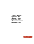
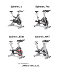
V-bike® Spinner® Spinner® Pro Spinner® Elite Spinner® NXT OWNER’S GUIDE TABLE OF CONTENTS _ Introduction . . . . . . . . . . . . . . . . . . . . . . . . . . . . . . . . . . .. . . . . . . . . . . . . . . . . . . . . . . . . . . . . . . . . . . . . . . . . . . . . . . Safety Instructions . . . . . . . . . . . . . . . . . . . . . . . . . . . . . . . . . . . . . . . . . . . . . . . . . . . . . . . . . . . . . . . . . . . . . . . . . . . . Assembly and Setup . . . . . . . . . . . . . . . . . . . . . . . . . . . . . . . . . . . . . . . . . . . . . . . . . . . . . . . . . . . . . . . . . . . . . . . . . . V-bike® Spinner® Assembly and Setup . . . . . . . . . . . . . . . . . . . . . . . . . . . . . . . . . . . . . . . . . . . . . . . . . . . . . . . . . . . . . . . Spinner® Pro / Elite / NXT Assembly and Setup . . . . . . . . . . . . . . . . . . . . . . . . . . . . . . . . . . . . . . . . . . . . . . . . . . . . . . . . Instructions for Use . . . . . . . . . . . . . . . . . . . . . . . . . . . . . . . . . . . . . . . . . . . . . . . . . . . . . . . . . . . . . . . . . . . . . . . . . . . Seat Adjustments . . . . . . . . . . . . . . . . . . . . . . . . . . . . . . . . . . . . . . . . . . . . . . . . . . . . . . . . . . . . . . . . . . . . . . . . . . . . . . . . Handlebar Adjustments . . . . . . . . . . . . . . . . . . . . . . . . . . . . . . . . . . . . . . . . . . . . . . . . . . . . . . . . . . . . . . . . . . . . . . . . . . . Pedal Strap Adjustment . . . . . . . . . . . . . . . . . . . . . . . . . . . . . . . . . . . . . . . . . . . . . . . . . . . . . . . . . . . . . . . . . . . . . . . . . . . Resistance Control . . . . . . . . . . . . . . . . . . . . . . . . . . . . . . . . . . . . . . . . . . . . . . . . . . . . . . . . . . . . . . . . . . . . . . . . . . . . . . . Smart Release™ System . . . . . . . . . . . . . . . . . . . . . . . . . . . . . . . . . . . . . . . . . . . . . . . . . . . . . . . . . . . . . . . . . . . . . . . . . . Training Information . . . . . . .. . . . . . . . . . . . . . . . . . . . . . . . . . . . . . . . . . . . . . . . . . . . . . . . . . . . . . . . . . . . . . . . . . . . Maintenance . . . . . . . . . . . . . . . . . . . . . . . . . . . . . . . . . . . . . . . . . . . . . . . . . . . . . . . . . . . . . . . . . . . . . . . . . . . . . . . . . Moving and Leveling . . . . . . . . . . . . . . . . . . . . . . . . . . . . . . . . . . . . . . . . . . . . . . . . . . . . . . . . . . . . . . . . . . . . . . . . . . . . . Preventive Maintenance . . . . . . . . . . . . . . . . . . . . . . . . . . . . . . . . . . . . . . . . . . . . . . . . . . . . . . . . . . . . . . . . . . . . . . . . . . . Adjustments . . . . . . . . . . . . . . . . . . . . . . . . . . . . . . . . . . . . . . . . . . . . . . . . . . . . . . . . . . . . . . . . . . . . . . . . . . . . . . . . . . . . Parts Replacement . . . . . . . . . . . . . . . . . . . . . . . . . . . . . . . . . . . . . . . . . . . . . . . . . . . . . . . . . . . . . . . . . . . . . . . . . . . . . . . . INTRODUCTION 2 3 4 4 7 13 13 14 14 14 15 15 16 16 16 18 19 _ Welcome to the world of STAR TRAC®. This manual will acquaint you with the assembly, operation and maintenance of your STAR TRAC group cycle. This manual provides information and instructions for the following group cycle models: • • • • 5700 Series - STAR TRAC V-bike® Spinner® 6800 Series - STAR TRAC Spinner® Pro 6900 Series - STAR TRAC Spinner® Elite 7000 Series - STAR TRAC Spinner® NXT Be sure to read and follow the information and instructions for your specific model before assembly, using or servicing your cycle. WARNING Your STAR TRAC group cycle is designed for aerobic exercise. Please check with your physician before beginning any exercise program. Do not push yourself to excess. Stop if you feel faint, dizzy or exhausted. Use common sense when exercising on the cycle. Star Trac and V-bike are registered trademarks of Star Trac. SPIN®, SPINNER® and SPINNING® are registered trademarks of Madd Dogg Athletics, Inc. Smart Release™ is a registered trademark of Nautilus, Inc. Page 2 STAR TRAC GROUP CYCLES OWNER’S GUIDE SAFETY INSTRUCTIONS _ INSTRUCTIONS The following fitness safeguards and operating precautions are directed to purchasers and users of STAR TRAC group cycles. Club Managers should ensure that members and fitness staff are trained to follow these same instructions. Failure to follow these safeguards may result in injury or serious health risk. FITNESS SAFEGUARDS • • • • Make your physician aware of any proposed fitness regimen before embarking on any exercise program. Discuss any health problems with your physician before beginning an exercise regimen. Stop operating the cycle if you feel faint, dizzy or tired. Preventive maintenance must be performed in accordance with the guidelines specified in the Preventive Maintenance section of this manual to assure optimum performance of the cycle. OPERATING PRECAUTIONS Persons exceeding 350 pounds (159 kg) may not use this product. Ensure that adjustment knobs (seat height, seat fore-and-aft) are properly secured and do not interfere with range of motion during exercise. • • • • • • • • • • Page 3 Do not use the cycle without proper footwear. NEVER operate the cycle with bare feet. Do not attempt to ride the cycle in a standing position at high RPMs until you have practiced at slower speeds. Never remove feet from the pedals while still in motion. Never attempt to abruptly stop the pedals, especially at high RPMs. Do not dismount the cycle until the pedals are at a complete STOP. After exercising, turn the load adjustment knob clockwise to increase resistance so the pedals will not rotate freely and potentially injure someone. Never turn the pedal crank arms by hand. Do not insert any object, hands or feet into any openings, or expose hands, arms or feet to the drive mechanism or other potentially moving part of the cycle. Keep children and pets away from the cycle whenever the machine is in use. Do not let children operate the cycle. The cycle mechanism and ergonomics are designed for adult use only. STAR TRAC GROUP CYCLES OWNER’S GUIDE ASSEMBLY AND SETUP _ ASSEMBLY AND SETUP V-BIKE® SPINNER® ASSEMBLY AND SETUP Use the following procedures to unpack and assemble your STAR TRAC V-BIKE SPINNER. UNPACKING Position the shipping carton so the “Heavy End” logo is located at the bottom. Open the top of the carton and fold back all four flaps. Carefully tilt the box forward so that the box may be lifted to expose the cycle. Remove all parts from the shipping carton and foam inserts, and verify that the following parts are included in your shipment: Assembly Parts Spare Parts Kit V-bike Parts List Description Qty. Description Main Frame Assembly (not shown) 1 I. Tension Handles w/Washers A. Handlebar 1 J. Tension Handles w/o Washers B. Seat 1 K. Water Bottle Brackets C. Handlebar Post 1 L. 8mm x 70mm (long) w/Washer and Nuts D. Seat Post 1 M. 8mm x 60mm (short) w/o Washer and Nuts E. Back Leg 1 N. Allen Wrenches, Metric F. Front Leg 1 O. Multi-Purpose Wrench G. Leveling Adjusters (pre-installed) 4 P. Spare Parts Kit (includes saddle, brake pad, bottom bracket assembly, tension handle, pedal straps) H. Pedals (set of two) 1 Spare Parts Kit- Save the box of spare parts in a safe place so you have service parts when needed in the future. Qty. 2 2 2 2 2 2 1 1 Take time now to enter your V-bike® Spinner® serial number in the space below (serial number is located on the bottom cross member). If parts are missing, or if you have any operational questions, please call Star Trac’s Service department at (800) 5031221; have your serial number ready. Serial No._____________________________________________ Page 4 STAR TRAC GROUP CYCLES OWNER’S GUIDE ASSEMBLY 1. Install the Back Leg Place the back leg in position at the rear of the cycle, aligning the two holes in the leg with the mating holes in the frame bracket. Insert two 8mm x 70mm bolts through the frame bracket and back leg, and install a flat washer and nut on each bolt. Using the #5 Allen Wrench and Multi-Purpose Wrench, tighten the nuts securely. Step 1 2. Installing the Front Leg Place the front leg in position at the front of the cycle, with the casters facing forward, aligning the two holes in the leg with the mating holes in the frame bracket. Insert the two 8mm x 60mm bolts through the frame bracket and front leg, and install a flat washer and nut on each bolt. Using the #5 Allen Wrench and Multi-Purpose Wrench, tighten the nuts securely. Step 2 3. Install the Pedals Install the pedals on the pedal cranks using the Multi-Purpose Wrench. The closed end of the pedal cage must point forward, toward the front of the cycle. NOTE: Turn the left pedal spindle counterclockwise when threading into the crank arm; turn the right pedal spindle clockwise when threading into the crank arm. Step 3 4. Install the Seat Insert the seat post into the frame assembly and secure in place using a tension handle. Position the seat on top of the seat post and secure in place using a tension handle and washer. NOTE: Tighten the tension handles firmly. Step 4 Page 5 STAR TRAC GROUP CYCLES OWNER’S GUIDE 5. Install the Handlebar Insert the handlebar post into the frame assembly and secure in place using a tension handle. Position the handlebar on top of the handlebar post and secure in place using a tension handle and washer. NOTE: Tighten the tension handles firmly. Step 5 6. Install the Water Bottle Holders Using the Allen Wrench, remove the two screws from the right side fork of the frame assembly. Position a water bottle holder in place against the frame assembly, and re-install the two screws to secure. Repeat to install the left-side water bottle holder. Step 6 You have now completed the assembly of your STAR TRAC V-BIKE® SPINNER®. Page 6 STAR TRAC GROUP CYCLES OWNER’S GUIDE SPINNER® PRO / ELITE / NXT ASSEMBLY AND SETUP Use the following procedures to unpack and assemble your STAR TRAC SPINNER ®. UNPACKING Prepare the area that you will be unpacking and assembling the bike to be free from debris that may cause damage. Observe all safety precautions and care while unpacking and assembling the bike. Position the shipping carton so the “Heavy End” logo is located at the bottom. Open the top of the carton and fold back all four flaps. Carefully tilt the box forward so that the box may be lifted to expose the cycle. Remove all parts from the shipping carton and foam inserts, and verify that the following parts are included in your shipment: Assembly Parts (Spinner Pro shown) NXT Parts List (not shown) Description Main Frame Assembly Handlebar Post Handlebar w/ Grip & Water Bottle Holders M8x1.25, 16mm Flat Head Screw M8x1.25, 16mm Socket Set Screw Seat Post Seat Slider Assembly w/ Saddle Pedals (set of two) Front Leg Assembly w/ Transport Wheels Spare Parts Kit Qty. 1 1 1 2 1 1 1 1 1 Description Rear Leg Assembly M10x1.5, 55mm Button Head Screw M10x1.5, 65mm Button Head Screw M10x1.5 Nyloc Hex Nut 10mm Washer, Flat Wrench Hex, 5mm Wrench Hex, 4mm Multi Wrench Spare Parts Kit (USA Only) (includes saddle, Qty. 1 4 4 8 16 1 1 1 1 brake pad, pedal straps) Pro/Elite Parts List (Pro shown above) Description Main Frame Assembly (not shown) Handlebar w/ Grip (& Water Bottle Holders – Elite only) (not shown) A. Seat Slider Assembly, w/ Saddle B. Seat Post C. Rear Leg Assembly D. Front Leg Assembly w/ Transport Wheels E. Pedals (set of two) Qty. 1 1 1 1 1 1 1 Description F. Water Bottle Cages G. Pop-Pins (pre-installed) G. M10x1.5, 55mm Flat Head Screw G. M10x1.5 Nut G. 10mm Washer, Flat G. Wrench Hex, 5mm G. Wrench Hex, 4mm G. Multi Wrench H. Spare Parts Kit (USA Only) (includes saddle, Qty. 2 3 4 4 4 1 1 1 1 brake pad, pedal straps) Spare Parts Kit- Save the box of spare parts in a safe place so you have service parts when needed in the future. Page 7 STAR TRAC GROUP CYCLES OWNER’S GUIDE Take time now to enter your V-bike® Spinner® serial number in the space below (serial number is located on the bottom cross member). If parts are missing, or if you have any operational questions, please call Star Trac’s Service department at (800) 5031221; have your serial number ready. Serial No._____________________________________________ NOTE: If you are missing any of the parts listed above, inspect the packing material and the box for items that may have been overlooked. If parts are missing, or if you have any product questions, please call Star Trac’s Service Department at (800) 503-1221, please have your Spinners serial number ready. CAUTION: Damage to the bike during assembly is not covered as part of the limited Star Trac warranty. Take care not to drop or lean the bike on the handle bar pop-pin. Carefully stand the bike up in the normal upright position on a stable surface so it will not tip over during assembly. Page 8 STAR TRAC GROUP CYCLES OWNER’S GUIDE ASSEMBLY Following these steps in order will minimize the build time and ensure proper assembly. Note: Not all of the following procedures are performed on all models; Spinner ® Pro, Elite and NXT. If the procedure is specific to a model it will be noted as follows: NXT Only, Pro/Elite Only, NXT/Elite Only, or Pro Only. 1. Install the Back Leg NXT Only Lift up the rear of the bike frame and place the rear leg assembly in position under the frame, aligning the holes in the leg with the holes in the frame. Position the leg so the thicker end faces toward the front of the bike Using the 5mm hex wrench and a 13mm combination wrench insert 2- M10X55mm (rear-most holes) and 2-M10X65mm (front-most holes) button head screws, nuts and washers (under bolt head and nut), to secure the rear leg assembly to the frame. Step 1 (NXT) Tighten all hardware securely using a torque wrench to 85 Inch Pounds Pro & Elite Only Lift up the rear of the bike frame and place the rear leg assembly in position under the frame, aligning the holes in the leg with the holes in the frame. Using the 5mm hex wrench and a 13mm combination wrench insert 2- M10X55mm flat head screws, nuts and washers to secure the rear leg assembly to the frame Tighten all screws/nuts securely using a torque wrench to 85 Inch Pounds Step 1 (Pro/Elite) 2. Install the Front Leg NOTE: The front foot assembly has wheels attached to the front edge. Be sure the wheels face forward when installing the front leg assembly. Stand the bike frame upright and gently tip the front of the bike up and position the front foot under the frame, with the wheels facing forward. Attach the front foot assembly to the frame, aligning the holes in the foot with the holes in the frame. NXT Only Position the leg so the thicker end and wheels face toward the front of the bike Using the 5mm hex wrench and a 13mm combination wrench insert 2- M10X55mm (rear-most holes) and 2-M10X65mm (front-most holes) button head screws, nuts and washers (under bolt head and nut), to secure the front leg assembly to the frame. Tighten all hardware securely using a torque wrench to 85 Inch Pounds Step 2 (NXT) Page 9 STAR TRAC GROUP CYCLES OWNER’S GUIDE Pro & Elite Only Using the 5mm hex wrench and a 13mm combination wrench insert 2- M10X55mm flat head screws, nuts and washers to secure the front leg assembly to the frame. Tighten all screws/nuts securely using a torque wrench to 85 Inch Pounds Step 2 (Pro/Elite) Move the bike to a flat surface and adjust the four leveling feet so the bike is stable. 3. Install the Saddle and Seat Slider Install the seat post into the frame and lower it to the lowest position and tighten the pop pin securely. Slide the seat slide into the top of the seat post with the saddle pointed towards the front of the bike. NXT Only Rotate the seat slider lock knob as needed so that the slider clamp is in alignment with the guide rail. There is a locking pin under the saddle that has to be pulled up as you move the slider into position. Release the pin when the indicator is within the 0 to 9 range. Step 3a (Pro/Elite) Step 3a (NXT) Test the seat slide for proper operation and full travel. Pro & Elite Only Unscrew the seat slider pin far enough to allow the slider to pass over the pin. Tighten screw with the slider in the 0 to 10 range. Test the seat slide for proper operation and full travel. Step 3b (Pro/Elite) Step 3b (NXT) 4. Install the Pedals NOTE: The pedal shafts are marked “R” and “L”. Trying to install the pedals on the wrong side may damage the pedal and the crank arm take caution to attach the pedals to the correct side of the bike. Install the pedals on the pedal cranks using a 15mm open-end wrench and tighten securely. Turn the left pedal spindle counterclockwise when threading into the left crank arm; turn the right pedal spindle clockwise when threading into the right crank arm. Step 4 Page 10 STAR TRAC GROUP CYCLES OWNER’S GUIDE 5. Install the Handlebar NXT Only Positioning the handlebar post with the number 1 on top and insert the handlebar into the handlebar sleeve locking it at number 4. Slide the handlebar onto the handlebar post insert with the water bottle holders facing forward and align the three screw holes. Insert the socket head set screw into the handlebar but do not tighten at this time. Insert the 2 flat head screws into the handlebar but do not tighten at this time. Check for proper alignment then tighten the 2 flat head screws using a 5mm hex wrench to 60 inch pounds. Tighten the set screw to 60 inch pounds using a 4mm hex wrench. Slide the handlebar post into the frame making sure the holes face the front of the bike. Step 5 (NXT) Allow the post to go into the frame all the way in to level 1 and align the pop pin so it snaps into the hole then tighten the pop pin and test for steadiness. Loosen the pop pin and raise the handlebar to its highest position number 10 and tighten the pop pin and test for steadiness. Pro & Elite Only Slide the handlebar post into the frame making sure the holes face the front of the bike. Allow the post to go into the frame all the way in to level 1 and align the pop pin so it snaps into the hole then tighten the pop pin and test for steadiness. Step 5 (Pro/Elite) Loosen the pop pin and raise the handlebar to its highest position and tighten the pop pin and test for steadiness. 6. Install the Bottle Holders (Pro Only) Using the 3mm Allen Wrench, remove the two screws from the right side fork of the frame assembly. Position a water bottle holder in place against the frame assembly, and re-install the two screws to secure. Repeat to install the cross member water bottle holder. Step 6 Page 11 STAR TRAC GROUP CYCLES OWNER’S GUIDE You have now completed the assembly of your STAR TRAC SPINNER® PRO / ELITE / NXT SPINNER PRO SPINNER ELITE SPINNER NXT Testing the Bike Use this checklist to perform the bike test procedure. Recheck all the bolts and make sure they are all tightened to the proper torque specification and no parts are missing. Test the handlebar and seat post to make sure they move freely and you are able to lock in at different positions. Check the seat to make sure it is level and tight and does not rotate around or tilt. Tighten and adjust as needed. Test the seat slide for movement front to rear and check it by settings it at different settings. CAUTION: The flywheel will continue to spin after you pedal and the crank arms and pedals will rotate with the flywheel. Brake tension is adjustable using the red resistance knob in the front of the bike. Pressing down on the knob will apply the brake if you need to stop quickly. Adjust seat post and handlebar post to your needs. Ride / test the bike for proper operation according to the owner's manual. Pedal the bike at a moderate pace and test for proper and smooth resistance changes while varying the amount of turns on the resistance knob. When the testing is complete tip the bike forward using the handlebars and roll it on a smooth surface to the final location and adjust the leveling feet so the bike is stable. Page 12 STAR TRAC GROUP CYCLES OWNER’S GUIDE INSTRUCTIONS FOR USE _ Your STAR TRAC group cycle is easy to use. Simply sit on the cycle, tighten the pedal straps and begin pedaling. The cycle allows the user full control over resistance by simply adjusting the brake pad. Typically, lower resistance levels enable you to pedal at a faster pace, placing increased demand on the cardiovascular system. Higher resistance levels will typically deliver a greater muscle/endurance workout at lower RPMs. RPM parameters in the Spinning® program range from 60 to 110 RPM. Additionally, the cycle offers seat and handlebar adjustments, allowing the cycle to be configured to each users comfort zone. This section provides the instructions for making seat adjustments, handlebar adjustments, pedal strap adjustments, and for controlling resistance. Differences between models are noted where applicable. PLEASE NOTE: Proper instruction from a certified Spinning® instructor should be used to properly fit the group cycle for use. SEAT ADJUSTMENTS Proper seat height helps ensure maximum exercise efficiency and comfort, while reducing the risk of injury. Adjust the seat height so that the knee joint is slightly flexed when the extended leg is at the bottom of the pedal stroke. Once the proper height has been achieved, adjust the seat forward or back so that when the feet are in the 3 o’clock and 9 o’clock positions, the knees are directly over the pedal axle. To adjust the seat height: (V-bike® Spinner®) Dismount the cycle. Loosen the seat height tension handle by turning the handle counterclockwise. Raise or lower the seat to the desired height, then tighten the tension handle by turning clockwise. Be sure to tighten the handle firmly. V-bike Spinner (Spinner® Pro/Elite/NXT) Dismount the cycle. Turn the seat height pop-pin counterclockwise and pull out on the pin to release it from its current preset location. Raise or lower the seat to the desired height, then gently release the pop-pin. Raise or lower the seat slightly, if necessary, until the pop-pin engages a preset hole. Turn the pop-pin clockwise to secure. To adjust the seat horizontal position: (V-bike® Spinner®) Dismount the cycle. Loosen the seat fore-and-aft tension handle by turning the handle counterclockwise. Move the seat forward or back to the desired position, then tighten the tension handle by turning clockwise. Spinner Pro/Elite Be sure to tighten the handle firmly. (Spinner® Pro/Elite/NXT) Dismount the cycle. Loosen the seat fore-and-aft tension knob by turning the knob counterclockwise. Move the seat forward or back to the desired position, then tighten the tension knob by turning clockwise. Spinner NXT Page 13 STAR TRAC GROUP CYCLES OWNER’S GUIDE HANDLEBAR ADJUSTMENTS Proper position for the handlebar is based primarily on comfort. Typically, the handlebar should be positioned slightly higher than the seat. All group cycles allow for adjustment of handlebar height. Additionally, the V-bike® Spinner® allows for fore andaft adjustment of the handlebar. To adjust the handlebar height: (V-bike® Spinner®) Loosen the handlebar height tension handle by turning the handle counterclockwise. Raise or lower the handlebar to the desired height, then tighten the tension handle by turning clockwise. Be sure to tighten firmly. V-bike Spinner (Spinner® Pro/Elite/NXT) Turn the handlebar height pop-pin counterclockwise and pull out on the pin to release it from its current preset location. Raise or lower the handlebar to the desired height, then gently release the pop-pin. Raise or lower the handlebar slightly, if necessary, until the pop-pin engages a preset hole. Turn the pop-pin clockwise to secure. To adjust the handlebar horizontal position: NOTE: Handlebar horizontal adjustment is available on the V-bike® Spinner® only. Loosen the handlebar fore-and-aft tension handle by turning the handle counterclockwise. Move the handlebar forward or back to the desired position, then tighten the tension handle by turning clockwise. Be sure to tighten the handle firmly. Spinner Pro/Elite PEDAL STRAP ADJUSTMENT The pedal straps should be adjusted to hold the foot snugly in the pedal. To adjust the pedal straps: Place each foot in the toe clip until the ball of the foot is over the pedal axle. The front of the shoe may not completely fill the toe cage. Rotate the pedals until one foot is within arms reach, then tighten the webbed cloth buckle until the cage Spinner NXT of the toe clip is snug around the foot. Repeat for the other foot. Point your toes and knees directly forward to ensure maximum pedal efficiency. V-bike Spinner V-bike Spinner RESISTANCE CONTROL Pedaling resistance is controlled by the Push Brake System knob located below the handlebar. Resistance adjustments can be made while riding to vary the intensity of your workout. Spinner Pro/Elite To adjust pedaling resistance: To increase resistance, turn the Push Brake System knob clockwise (+); to decrease resistance, turn the knob counterclockwise (-). In case of emergency, you may press directly down on the Push Brake System knob to bring the flywheel to an abrupt stop. Spinner NXT Page 14 STAR TRAC GROUP CYCLES OWNER’S GUIDE SMART RELEASE™ SYSTEM (Spinner® Elite) Allows the benefits of the direct drive system with a safety clutch to release the crank from the direct drive when a force is applied to the pedals. TRAINING INFORMATION _ This section provides hints on how to stay motivated, and suggestions for getting the most out of your workouts with maximum ease, efficiency and enjoyment. IMPORTANT: User should be aware of the features, functions and proper operation of the cycle before using the cycle for the first time. BEFORE BEGINNING Be sure the seat, handlebar and pedal straps are properly adjusted for your body size and comfort before beginning your workout. WARM-UP Once you are in position and sitting on the cycle with your hands in a comfortable position on the handlebar, slowly begin pedaling. A gradual warm-up prepares the muscles and cardiovascular system for a more intense workout, and helps prevent potential injuries from occurring. Your warm-up should be sufficient once your breathing rate begins to increase and you begin to perspire lightly. The warm-up period should last about five minutes. WORK OUT A brisk and rhythmic workout will train the muscles and cardiovascular system to perform at a higher efficiency. The key is to exercise aerobically; typically at 60% – 75% of your maximum heart rate. For added enjoyment, comfort and variety during your workout, experiment with seated or standing positions, resistance level, and hand positions. COOL-DOWN Slow and relaxed activity after a workout allows the muscles and cardiovascular system to gradually return to an inactive state. DISMOUNTING THE CYCLE WARNING: The flywheel momentum of the cycle will keep the pedals turning even after the user stops pedaling, or in the event the user’s feet slip off the pedals. DO NOT DISMOUNT THE CYCLE OR REMOVE YOUR FEET FROM THE PEDALS UNTIL BOTH THE PEDALS AND THE FLYWHEEL HAVE STOPPED COMPLETELY. Failure to comply may lead to loss of control and serious personal injury. You may stop the cycle using any of the following methods: o Pedal more slowly until the pedals come to a complete stop. o Increase the resistance by turning the Push Brake System knob clockwise (+) until the pedals come to a complete stop. o Push down on the Push Brake System knob until the pedals come to a complete stop. o (Spinner® Elite only) Apply back pressure to the pedals to engage the Smart Release™ system. Continue applying pressure until the pedals and flywheel come to a complete stop. Page 15 STAR TRAC GROUP CYCLES OWNER’S GUIDE MAINTENANCE _ This section provides the procedures to maintain the group cycles in serviceable condition. Differences between models are noted where applicable. MOVING AND LEVELING To move the cycle to a new location: Lift the cycle from the rear and use the front wheels (located on the front leg, below the handlebar) to roll the cycle from one location to another. To level the cycle: Use the four leveling adjusters (located on the underside of the front and rear legs) to compensate for uneven floor surfaces. PREVENTIVE MAINTENANCE Perform regular scheduled preventive maintenance procedures to maintain your group cycle in serviceable condition. AINTENANCE TOOLS Tools required for service and maintenance of your group cycle are listed below. Tool Pedal Wrench, 15mm* Shimano-compatible Bottom Bracket Tool* Cotterless Crank Puller* Metric Allen Wrench Set and Metric Socket, 2mm ~ 6mm Crescent (adjustable) Wrench Torque Wrench * Available at local bike or fitness-related stores. Purpose Remove and install pedals. Remove, install and adjust the bottom bracket. (V-bike only) Remove crank. Install and adjust leg bolts, chain tensioner, brake pad and crank bolts. Adjust chain tension. Adjust crank arm. DAILY MAINTENANCE The service life of your group cycle will be determined by how consistently you perform the daily maintenance procedures. Dry the group cycle after each use to remove sweat and moisture. It is best to use a liquid non-abrasive cleaner and water solution. Wipe Down / Cleaning To prevent the build-up of rust and other forms of corrosion, wipe down the cycle at the end of each day (or preferably at the end of each class). Raise all posts to the highest setting to expose moisture. Using an absorbent cloth, focus on all areas that perspiration can settle. Give particular attention to the following areas: o Handlebar o Seat / adjustable slide for the seat o Flywheel o Back leg assembly o Chain guard o Brake knob and bolt assembly o Pop-pins o Leveling feet NOTE: Never use abrasive cleaning liquids or petroleum-based solvents when wiping down the cycle. NOTE: It is recommended that class instructors direct class participants to release all the tension from the cycle at the end of each class to allow perspiration to evaporate. Page 16 STAR TRAC GROUP CYCLES OWNER’S GUIDE Inspection / Adjustment Inspect major moving parts that require constant proper torque. Loose or misadjusted parts can result in personal injury or damage to the cycle. Check the following parts for security and/or proper torque. Crank arms Use a foot pound torque wrench, tighten to 30 - 35 foot-pounds. Pedals Use a pedal wrench. Verify that the pedal is not cross-threaded. IMPORTANT: If your facility allows members to interchange pedals, it is critical that the pedals are checked after each class to prevent damage, which may lead to injuries if ignored. Water bottle (V-bike & Spinner Pro) Tighten down assembly screws. NOTE: Water bottle cages are easily damaged when oversized bottles are forced to fit within the bottle cage. Checking and tightening the screws will help prevent damage. WEEKLY MAINTENANCE Weekly maintenance should focus on the overall performance of the group cycle. During these inspections, look for vibration and possible loose assemblies. Have an experienced rider ride each cycle to identify and help diagnose any vibration, noises, and any "unusual" feeling from the drive chain. Either faulty flywheel alignment or a loose chain can cause vibration. o Check for proper flywheel alignment. Torque flywheel nuts as necessary. o Remove chain guard and check for loose chain. Adjust chain as necessary (refer to "Chain Adjustment" on page 14). o Inspect The Bottom Bracket Assembly (BBA). The BBA will come loose periodically and require tightening. Loose play (left and right motion) indicates the BBA needs adjusting. (V-bike only) Inspect each cycle for loose assemblies, parts, bolts and nuts. Give particular attention to the following: o Tighten all frame base hardware. o Tighten all pull pin handles. o Tighten seat hardware. o Tighten pedal toe clip / toe straps. o Inspect and tighten tension knob assembly. MONTHLY MAINTENANCE The monthly maintenance check should be a comprehensive inspection of the overall frame and main assembly components of the group cycle. Inspection Inspect the frame and main assembly components for rust or corrosion. Tilt the cycle or place in an upside down position to locate areas where rust and corrosion may develop. Use a small, wire brush to remove rust build-up in small crevasses, such as leveling feet, pop pin handles and other bolt assemblies. Give particular attention to the following areas: o Leveling feet o Pop pin handles Inspect all wear items for adjustments or possible part replacement. Give particular attention to the following: o Inspect brake pad for wear. Excessive wear, such as glazing or leather separation, indicates replacement is required. o Inspect seat pad for wear. Rips, tears or excessive movement indicates replacement is required. o Inspect pedals for play. Excessive movement of pedals indicates replacement is required. Page 17 STAR TRAC GROUP CYCLES OWNER’S GUIDE Drive Chain Lubrication The drive chain will require lubrication once a month, or after every 100 hours of use. The chain should be lubricated with a light oil (preferably a lubricant that comes with a spray hose that fits in front of the can) and a dry clean towel. 1. Remove the chain guard covers to expose the drive chain. 2. Using a bristle-type brush, remove any corrosion or debris from the drive chain. CAUTION: DO NOT rotate the flywheel or crank arm when lubricating. DO NOT lubricate the drive chain while flywheel is in motion. NEVER expose hands into any part of a moving drive chain. DO NOT wrap a towel around the chain while in motion. 3. With one hand, carefully spray small sections of the drive chain with lubricant; with the other hand, carefully hold a clean towel underneath the area being sprayed to absorb any excess. 4. Reinstall the chain guard covers. 6-MONTH MAINTENANCE The flywheel on the Spinner® Elite must be lubricated with spray grease specified as Lithium high-temperature / highspeed (Grade NLGI #2) every six months. This will prolong bearing life and help prevent serious damage that may lead to personal injury if ignored. IMPORTANT: Failure to perform this procedure will void your warranty. 1. Turn the flywheel until the grease slot is visible. 2. Insert the spray tube into the grease slot, then apply the grease (one squirt) into the slot. NOTE: When applying the grease, take care to avoid spraying grease on the clutch plates of the flywheel. Spray ONLY in the grease slot and around the nut in the center of the hub. DO NOT over grease. Spinner Elite 3. Remove the spray tube from the grease slot, and rotate the flywheel for one or two revolutions. 4. Repeat steps 1 through 3 a total of five times so the grease is evenly distributed inside the hub. 5. Clean any excess grease or overspray from the outside of the flywheel. 6. Test cycle operation for smoothness. Test the Smart Release™ mechanism by pedaling fast, then stopping abruptly. The flywheel should coast to a stop within five to seven revolutions. ADJUSTMENTS CHAIN ADJUSTMENT The chain on your group cycle has been factory set and lubricated. It should not require adjustment initially. Over time, however, you may need to adjust the tension. CAUTION: Improper chain adjustment will cause premature wear and may void the warranty. 1. Using a 3mm Allen Wrench, remove the three screws supporting the plastic chain shrouding. Diagram A 2. With an adjustable wrench, loosen the two nuts on either side of the flywheel (Diagram A). Page 18 STAR TRAC GROUP CYCLES OWNER’S GUIDE 3. Tighten the two bolts that go through the frame, moving the flywheel forward by turning clockwise, until there is approximately 3/16” of slack in the chain (Diagram B). 4. Re-tighten the two bolts on the sides of the flywheel and replace the chain shrouding. NOTE: If the chain is too tight, typically the rider will feel a strong vibration between 20 and 50 RPMs. If this happens, loosen the bolts 1/2” turn until the vibration disappears, then tighten the lock nuts. Diagram B PARTS REPLACEMENT BRAKE PAD REPLACEMENT NOTE: The flywheel and crank assembly have been removed from Diagram C to better illustrate the brake pad assembly. This is not required when replacing the brake pad. Removal 1. Remove tension from the brake pad by turning the Push Brake System knob counterclockwise, until completely loose. Diagram C 2. Using the Multi-Purpose Wrench, remove the two bolts supporting the brake pad onto the frame (Diagram C). Installation 1. Carefully re-install the two bolts through the brake pad bracket onto the frame. Tighten by using the Multi-Purpose Wrench. CHAIN REPLACEMENT Removal 1. Using a 3mm Allen Wrench, remove the three screws supporting the plastic chain shrouding. 2. Using the 5mm Allen Wrench, remove the flywheel axle bolts (Diagram D). 3. Loosen the chain tension bolts (Diagram E). Slide the flywheel off the frame by pulling it toward the back of the bike. This will allow you to slide the flywheel back and drop down, then carefully pull the flywheel out from the back frame brackets. Next, gently remove the chain from the crank sprocket and flywheel cog. Diagram D Installation 1. Install the new chain on the crank sprocket and on the cog attached to the flywheel. 2. Insert flywheel into the back brackets of the frame, sliding in, then up and in. 3. Tighten the chain tension bolts until chain has about 3/16” of slack. Verify the flywheel is straight within the frame of the bike. Tighten lock nuts. Insert and tighten flywheel axle bolts and re-install the plastic chain shroud. Diagram E Page 19 STAR TRAC GROUP CYCLES OWNER’S GUIDE STAR TRAC 14410 Myford Road Irvine, California 92606 Telephone: (800) 228-6635, (714) 669-1660 Fax: (714) 508-3303 http://www.startrac.com Part Number 620-7302, Rev. B October 2004