1
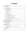
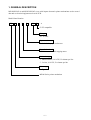
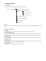
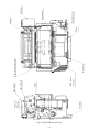
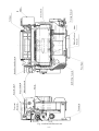
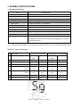
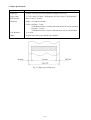
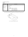
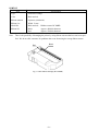
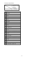
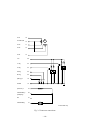
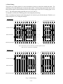
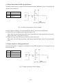
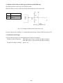
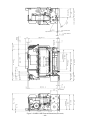
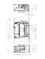
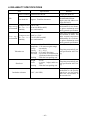
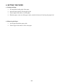
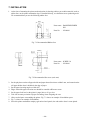
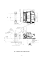
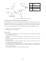
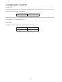
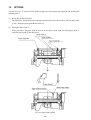
DOT MATRIX PRINTER MECHANISM MP111MP-24G-A MP115MP-24G-A SPECIFICATION AND OPERATION MANUAL NOTICE • All rights reserved. Reproduction of any part of this manual in any form whatsoever, without STAR’s express permission is forbidden. • The contents of this manual are subject to change without notice. • All efforts have been made to ensure the accuracy of the contents of this manual at the time of going to press. However, should any errors be detected, STAR would greatly appreciate being informed of them. • The above notwithstanding, STAR can assume no responsibility for any errors in this manual. Copyright 1999 Star Micronics Co., LTD. Contents 1. GENERAL DESCRIPTION ................................................................................................................ 1 2. CONSTRUCTION ................................................................................................................................ 2 2.1 Configuration ........................................................................................................................... 2 2.2 Principle of Operation .............................................................................................................. 2 3. GENERAL SPECIFICATIONS .......................................................................................................... 5 3.1 Printing Specifications ............................................................................................................. 5 3.2 Paper Specifications ................................................................................................................. 6 3.3 Ink Ribbon Specifications ........................................................................................................ 7 3.4 Connector Specifications ......................................................................................................... 9 3.5 Print Timing ........................................................................................................................... 11 3.6 Timing Chart .......................................................................................................................... 12 3.7 Print Head Specifications ....................................................................................................... 14 3.8 CR Motor Specifications ........................................................................................................ 18 3.9 Paper Feed Motor Specifications ........................................................................................... 20 3.10 Ribbon Shift Solenoid (RS-SOL) Specifications ................................................................... 21 3.11 Timing Signal Detector Specifications .................................................................................. 22 3.12 Home Position Detector (HP-sig) Specifications .................................................................. 23 3.13 Paper-out Detector (PE-sig) Specifications ........................................................................... 23 3.14 Ribbon Position Detector (RS-sig) Specifications (MP115MP only) ................................... 24 3.15 Dimension and Weight .......................................................................................................... 24 4. RELIABILITY SPECIFICATIONS ................................................................................................. 27 5. SETTING THE RIBBON CARTRIDGE ......................................................................................... 28 6. SETTING THE PAPER ..................................................................................................................... 29 6.1 Setting the Paper .................................................................................................................... 29 6.2 Removing the Paper ............................................................................................................... 29 7. INSTALLATION ................................................................................................................................ 30 8. OPERATIONAL NOTES .................................................................................................................. 35 8.1 Power ON/OFF Note ............................................................................................................. 35 8.2 Carriage Motor Protection Method (Against Mechanical Errors) ......................................... 36 8.3 Other Notes ............................................................................................................................ 36 9. POWER SUPPLY CAPACITY ......................................................................................................... 37 9.1 24 V Line ............................................................................................................................... 37 9.2 5 V Line ................................................................................................................................. 37 10. OPTIONS ............................................................................................................................................. 38 1. GENERAL DESCRIPTION MP111MP-24G-A and MP115MP-24G-A are serial impact dot matrix printer mechanisms used to record data and as electrical equipment such as for ECR. Model Name Notation MP1 1 1 M P - 24 G - A G: FG compatible Voltage 24 : 24 VDC Paper-out detector P : Includes the paper-out detector Paper feed method M : Friction method and stepping motor Mechanism type 1 : Monochromatic, 16.9 CPI, 32 columns per line 5 : 2 colors, 16.9 CPI, 32 columns per line Printer type 1 : Type 1 MP100 Series printer mechanism –1– 2. CONSTRUCTION 2.1 Configuration This printer mechanism is composed of the following components. Printer mechanism Drive unit, gears, and carriage unit Detectors Timing detector Home position detector Paper out detector Paper feed mechanism Ink ribbon wind mechanism Print head unit Frame unit Other You can also use 1.75 inch (45 mm) width roll paper by removing the paper guide B and attaching the optional guide. 2.2 Principle of Operation 2.2.1 Drive This printer mechanism moves the print head, feeds paper and feed ribbon with the motor. 2.2.2 Print head movement The rotation of the motor is transmitted to drive shaft through the reduction gears. The carriage makes lateral reciprocal movements along a groove that is carved on this drive shaft, consequently moving the print head. 2.2.3 Print timing Printing is done when the timing signal is generated synchronized with the rotation of the motor, based on the home position signal. 2.2.4 Ribbon feed The ink ribbon is housed inside a ribbon cartridge in endless fashion. A ribbon feed roller is turned by the rotation of the motor whereby the ink ribbon is wound up. 2.2.5 Paper feed Paper feeding is done by the rotation of the stepping motor. –2– Fig. 2-1 MP111MP External view –3– Connector Paper-out Detector Ink Ribbon Cassette Platen Paper Guide B Paper Guide A Print Head Home Position Detector Motor PF Motor Timing Detector Drive Shaft Carriage Fig. 2-2 MP115MP External view –4– Connector Paper-out Detector Print Head Home Position Detector Ink Ribbon Cassette Platen Ribbon Solenoid Paper Guide B Paper Guide A Ribbon Position Detector Motor PF Motor Timing Detector Drive Shaft Carriage 3. GENERAL SPECIFICATIONS 3.1 Printing Specifications Item Printing method Printing configuration Printing direction Printing speed Printing lines Character dimension Dot spacing Printing area Paper feed speed Wire diameter Line space Specifications Impact Dot Matrix 7 x 9 (half dot) or 5 x 9 Bidirectional (See note 1) Approximately 3.85 lines/second 32 lines (when using 7 x 9 half dots) Width 1.2 mm (when using 7 x 9 half dots) Height 2.42 mm Horizontal 0.3 mm (with full dots) Vertical 0.353 mm 48 mm Approximately 3.77 in./sec. (continuous feeding) ø 0.3 mm 1/6, 1/8, 1/12, 1/72, 1/144 inches Feed paper more than one line before printing graphics or vertically expanded characters. Note 1: When performing bidirectional printing, horizontal drift is likely to occur in unidirectional printing. Details of Character Dimentions 1 Paper width 2 Fonts configuration (H x V) 3 4 5 6 CPI Printing column count Spacing e mm Character dimensions c mm d mm 7 Dot space a mm b mm 8 Total no. of dots 9 Printing area mm 2.25 inches (57.5 mm) 7x9 5x9 (half) 16.9 14.1 32 26 1.5 1.8 1.2 1.5 2.42 2.42 0.3 0.3 0.353 0.353 160 156 48 46.8 1.75 inches (44.5 mm) Optional 7x9 5x9 (half) 16.9 14.1 24 20 1.5 1.8 1.2 1.5 2.42 2.42 0.3 0.3 0.353 0.353 120 120 36 36 Fig. 3-1 Character Size (7x 9 font) –5– 3.2 Paper Specifications Item Specifications Paper type Ordinary roll paper (1P) and carbonless roll paper (2P or 3P) Paper width 57.5 ± 0.5 mm (2.25 inch). With options, 44.5 ±0.5 mm(1.75 inch) possible Roll diameter Max. 85 mm (3.35 inch) Thickness Single : 0.07 mm to 0.10 mm Copies : Original + 1 copy Total thickness max. 0.14 mm, with each sheet 0.05 to 0.08 mm thick Original + 2 copies Total thickness max. 0.2 mm, with each sheet 0.05 to 0.08 mm thick Core diameter 12 ± 1 mm Other No glue between the paper and the core diameter Fig. 3-2 Paper spec. & Print area –6– 3.3 Ink Ribbon Specifications 1) MP111 Item Specifications Type Dedicated cartridge Color Purple (standard) Ribbon material Nylon 66 Ribbon size Width: 13 mm Model name Purple (standard): Ribbon cassette RC100 P Black (optional): Ribbon cassette RC100 B Ribbon life Purple: Black: Note: Approx. 1,500,000 characters Approx. 800,000 characters There is the possibility of damaging the printer by using ribbon cassettes that have not been specified. We do not offer warrantee for problems that occur from using the wrong ribbon cassette. Fig. 3-3 Ink ribbon cartridge (RC100 P.B.) –7– 2) MP115 Item Specifications Type Dedicated cartridge Color Black and red Ribbon material Nylon 66, (#40 denier) Ribbon size Width: 13 mm Model No. Black and red: Ribbon cassette RC100BR Ribbon life Black: Red: Approx. 400,000 characters Approx. 250,000 characters Note: There is the possibility of damaging the printer by using ribbon cassettes that have not been specified. We do not offer warrantee for problems that occur from using the wrong ribbon cassette. Red Black Fig. 3-4 Ink ribbon cartridge (RC100BR) –8– 3.4 Connector Specifications Connection Drawing 1 2 3 4 5 6 7 8 9 10 11 12 13 14 15 16 17 18 19 20 21 22 23 24 25 26 27 28 Connector Type NIPPON FCI HLEM28R-1 See next page HD #6 HD CMN HD #4 HD #5 HD #1 HD CMN HD #2 HD #3 HD CMN HD #7 HD #8 HD #9 LF-ø4 LF-CMN A, B LF-ø2 LF-ø1 LF-ø3 RS-Sig (Ribbon shift) MP115M only S-GND PE-Sig CR MOTOR (–) HP-Sig RS-SOL (Ribbon shift) MP115M only T2-Sig T1-Sig +5V NC CR MOTOR (+) (CMN VH) –9– LF-ø1 16 LF-CMN A,B 14 LF-ø3 17 LF-ø2 15 LF-ø4 13 M +5V 26 T1-sig 25 T2-sig 24 HP-sig 22 PE-sig 20 (RS-sig) *1 18 S-GND 19 (RS-SOL) *1 23 CR MOTOR(+) (CMN(VH)) 28 NC 27 CR MOTOR(-) 21 M *1 MP115MP only Fig. 3-5 Connector connections – 10 – 3.5 Print Timing This printer uses a timing signal of 1 as the total number of pulses to control the solenoid and motor. The numbering of Tn of the timing signal 1 is found as shown below. The first timing signal 2 after the rise of the home position signal is detected and the fall of the first timing signal 1 after the rise of timing signal 2 is set as T-1. The subsequent timing signal falls are set as T0, T1 and T2. You should be careful of the following points concerning this print timing. There is a minimum of 2 pulses for the timing signal 1 for electrical cycles for the same pin. Therefore, you cannot energize Tn, Tn+1 using the same pin. 7✕9 (half) font Forward printing Normal character Rotated character T2 T4 T6 T8 T10 T12 T14 T16 T18 T20 T22 T1 T3 T5 T7 T9 T11 T13 T15 T17 T19 T21 T312T314T316T318T320T322 T311T313T315T317T319 T321 1st chara 2nd chara 32th chara 1 3 5 7 2 4 6 1 3 5 7 2 4 6 1 3 5 7 2 4 6 7 5 3 1 6 4 2 7 5 3 1 6 4 2 7 3 1 1 6 4 2 32th chara 31th chara 1st chara Backward printing T754T752T750T748T746 T744 T742T740T738T736 T734 T753T751T749T747T745T743 T741T739T737T735T733 T444T442T440T438T436 T434 T443T441T439T437T435T433 Note ) The electric cycles for identical 1 pins has 2 pulses or more. There Tn, Tn+1 electricity is impossible 5✕9 font Forward printing T2 T4 T6 T8 T10 T12 T14 T16 T18 T20 T22 T1 T3 T5 T7 T9 T11 T13 T15 T17 T19 T21 1st chara Normal character Rotated character 1 2 3 4 5 2nd chara 1 2 3 4 5 4 3 2 26th chara Backward printing T754T752T750T748T746 T744 T742T740T738T736 T734 T753T751T749T747T745T743 T741T739T737T735T733 Fig. 3-6 Print Timing – 11 – T310 T312T314 T316T318T320T322 T309 T311T313T315T317T319 T321 26th chara 1 2 3 4 5 5 4 3 2 1 1st chara T446 T444T442T440T438T436 T434 T445 T443T441 T439T437T435T433 ON After print Motor OFF Timing OFF HIGH HP-sig LOW HIGH T2-sig – 12 – Fig. 3-7 Printing action LOW T0 T2 T4 T-1 T1 T3 T322 T323 T433 T490 T754 T755 T-1 T0 (T863) T1 HIGH T1-sig LOW Forward print area (322 pulses) PRINT Carriage reversal Carriage reversal area (110 pulses) area (110 pulses) TYP. 66.3 ms MIN. 64.3 ms Backward print area (322 pulses) ON PF MOTOR 1/6 Inch = 24 Steps T1-sig: Type 1660 Hz, Max. 1710 Hz (Software and CPU should be designed at Max. 2000 Hz.) Printing speed: T1-sig 1600 Hz = Approximately 3.84 lines/sec. 1710 Hz = 3.96 lines/sec. Paper feed action must be carried out within the carriage reversal area. TYP. 66.3 ms MIN. 64.3 ms Forward print area 3.6 Timing Chart (1) Printing Action MOTOR (2) Ribbon Shift Operation (Only with 2 color printing on the MP115) Release Action MOTOR ON OFF T1 T2T3 T30 T336 HIGH TIMING SIG-1 RIBBON SHIFT LOW ON OFF 18 Pulses ROTATE RIBBON SHIFT GEAR 288 Pulses STOP Ribbon shift gear rotation: 18 x 6 x 32/12 = 288 pulses Fig. 3-8 Release action – 13 – 3.7 Print Head Specifications (1) Basic Specifications Item Specifications Supply voltage 24 VDC ± 2.4 V Response frequency Max. 900 Hz Energized time See below Coil resistance 14.7 ± 0.4 Ω (includes cable resistance) Peak current 1.0 A/solenoid (for 24 VDC, 375 µs) Timing Energizing is begun at the fall of the output signal of timing signal 1. Energizing cycle shall be 2 pulses or more of timing signal 1. Typ. Max. Peak current 1.0 A 1.1 A Condition 24 V 375 µs 26.4 V 340 µs Transistor’s turn off delay time (td): 2 µs Fig. 3-9 Current waveform (µs) Energizing Time 415 395 375 355 340 21.6 22.8 24 25.2 26.4 (V) Voltage Fig. 3-10 Head Energizing Time - Head Power Supply Voltage – 14 – We employ a zener diode to control spike voltages that occur when the transistor is turned OFF. The following figure shows and example of the drive circuit. With this circuit, we use a transistor equipped with a zener diode (zener voltage 60 + 10/-5V) between the base and collector. TR1 R1 R2 VH 2SD2041 (ROHM) 1K Ω 330Ω 23V + TR1 for VCE (sat) = 24 V HV (24 V) Fig. 3-11 Example of Print Solenoid Drive Circuit – 15 – (2) Pre-fire This operation applies minute vibrations to the needle wire to allow for its smooth movement as printer warmup. Pre-fire is performed under the following conditions. The energizing time is too short to allow for the printing action to occur. Operating time Frequency Energizing time When power is turned ON. 900 Hz 175 ± 5 µs Number of times Power supply voltage 32 Times DC24V ±2.4 V (3) Print Duty This print head is not equipped with a head temperature detector. Therefore, use the printer within the maximum printing ratio shown below. If you print exceeding this printing ratio, you can damage the printer. Ambient Temperature 25°C 1140 Print Ratio N (dot /sec) Ambient Temperature 50°C 830 21.6 V 24.0 V 26.4 V Fig. 3-12 Print duty The figure above shows the print duty that is possible with continuous printing when each wire is used an equivalent number of times. In this case, you can calculate the possible dot count for D per character using the following numerical formula. N (Print Ratio) x T (Print time per line includes the time of the paper feed [sec]) L (number of character per line) – 16 – [dot/chara] When you use the specific wires many times, make sure the maximum print ratio is not over the print duty shown in Fig. 3-13. Fig. 3-13 shows operation at 24.0V. (1200) 1200 Ambient Temperature 25°C Print Ratio N (dot/sec) 1100 (1155) 1100 (1030) 1000 950 900 890 (850) (840) 800 (785) 750 700 (730) 680 600 (615) 500 550 500 400 Ambient Temperature 50°C 380 1 2 3 4 5 6 7 Number of the specific wires Fig. 3-13 Print duty (specific wires) – 17 – 8 3.8 CR Motor Specifications Item Specifications Type DC motor Supply voltage 24 VDC + 1.2 V Start current Max. 1.6 A Average current Approx. 0.15 A Fig. 3-14 Current waveform of the motor – 18 – Fig. 3-15 Motor drive circuit (example) R1 R2 R3 R4 R5 R6 R7 C1 C2 C3 10 KΩ 3.3 KΩ 6.8 KΩ 1/6 W 2.2 KΩ 1.2 KΩ 10 KΩ 20 KΩ 0.47 µF (Film) 0.033 µF (Film) 0.022 µF (Film) TR1 TR2 TR3 TR4 TR5 TR6 IC1 IC2 VR 2SA950 2SC1740 2SA1175 2SD882 2SB1359 2SD1637 SN74LS05 M51971L (MITSUBISHI) 6.8 KΩ Notes: Adjust motor speed with VR adjustment and T1 signal to 1660 Hz ± 30 Hz. 3.8.1 FG Circuit The motor control circuit with a Frequency Governor circuit maintains the printing speed at the settings. It is mainly constructed of a Speed Control IC (IC2) and a Power Transistor TR6 shown in Fig. 3-15. It measures the number of rotations of the Carriage Motor from the Timing Signal 1. This signal is then compared to the standard signal to control the speed by controlling the voltage energizing the Carriage Motor. 3.8.2 Merits of the FG Circuit The FG circuit maintains a stable output regardless of the environment where it is being used. It maintains stability even at high speeds. It protects the head because the speed is stable. – 19 – 3.9 Paper Feed Motor Specifications Item Specifications Type PM type stepping motor Drive method 2-Phase excitation unipolar method Terminal voltage 24 VDC ± 1.2 V (for drive), 4.2 VDC (when holding) Peak current Max. 0.7 A Average current About 0.28 A Holding current About 0.08 A Amount of paper feed 1/144 inch per 1 step Feed method Forward feed only Excitation signal a. When paper feed amount is less that 4 steps. Set to 350 pps drive. b. When paper feed amount is over 5 steps and less than 8 steps. Set the slowdown area so that the final 2 steps become 300 pps and 200 pps. The other areas are set to 350 pps drive. c. When paper feed amount is over 9 steps and less than 18 steps. Set the inital 4 steps so that they become 350 pps (slow-up area). Set the slow-down area so that the final 4 steps become 500 pps, 400 pps, 300 pps, and 200 pps. The other areas are set to 550 pps drive. d. When paper feed amount is over 19 steps. Set the initial and final 4 steps so that they become 350 pps. The other areas are set to 550 pps drive. VH TA1 TR1 TR2 24 V µPA1428AH (NEC) 2SB1359 Compatible 2SC1740 Compatible D1 R2 to R3 D1 IC DSM1D1 (HITACHI) 10 kΩ DSM1D1 (Hitachi) SN74L04 15 13 Fig. 3-16 Drive circuit of paper feed motor (example) – 20 – 3.10 Ribbon Shift Solenoid (RS-SOL) Specifications MP115MP only Item Specifications Supply voltage 24 VDC ± 1.2 V Pulse width T1-sig 18 pulses (Approx. 12 ms) Coil resistance Approx. 57.0 Ω Average current Approx. 400 mA Fig. 3-17 Current waveform of RS-SOL Fig. 3-18 RS-SOL drive circuit (example) TR1 2SD2010 (ROHM) D1 DSM1D1 R1 1 kΩ R2 330 Ω VH 23 V + TR1 VCE (sat.) = 24 V – 21 – 3.11 Timing Signal Detector Specifications The timing signal detector is composed of a detection slit mounted on the motor shaft, a photo interruptor, and waveform shaping circuit. Timing signal 1 is generated 18 pulses and timing signal 2 is generated 1 pulse every time the motor rotates by 1 turn. PS TR1 Photo interruptor ON1004R (MATSUSHITA) 2SC1740 R1 4.7 kΩ R2 56 kΩ R3 150 Ω C1 2200 PF Fig. 3-19 Circuit of timing signal 1 (example) PS TR1 Photo interruptor ON1004R (MATSUSHITA) 2SC1740 R1 4.7 kΩ R2 56 kΩ R3 150 Ω C1 2200 PF Fig. 3-20 Circuit of timing signal 2 (example) – 22 – 3.12 Home Position Detector (HP-sig) Specifications The home position detector is composed of the mechanical switch. While the carriage is located at the left end, the switch remains ON. R1 10 kΩ R2 15 kΩ C1 0.022 µF Fig. 3-21 Home position detector circuit (example) In order to improve reliability, we recommend that the HP-sig is detected as described below. (1) When the T1-sig is unstable when turning on the power, etc. Detect the L level after having detected the H level of the HP-sig, and then, after having carried out 81 pulse counts for the T1-sig, detect the H level. (2) When the T1-sig is decided during continuous operation of the motor Detect the L level of the HP-sig, and then, after having counted 847 pulses of the T1-sig, detect the H level. 3.13 Paper-out Detector (PE-sig) Specifications The Paper-out Detector is composed of a mechanical switch. While the paper is set in the paper tray, the switch remains ON. R1 10 kΩ R2 15 kΩ C1 0.022 µF Fig. 3-22 Paper-out detector circuit (example) – 23 – 3.14 Ribbon Position Detector (RS-sig) Specifications (MP115MP only) The ribbon position is made up by a mechanical switch. When the ribbon is at the position for printing of black characters, the switch is ON. R1 10 kΩ R2 15 kΩ C1 0.022 µF Fig. 3-23 Example of ribbon position detection circuit In order to improve the reliability, we recommend that the RS-sig is detected while the motor is off. 3.15 Dimension and Weight See Fig on the next page for external dimension of the printer mechanism. Weight of printer mechanism: MP111MP, approx. 410 g (excludes the ribbon cartridge) MP115MP, approx. 450 g (excludes the ribbon cartridge) Weight of ink ribbon cartridge: approx. 24 g – 24 – Paper Entrance Paper Entrance Paper Entrance Paper Entrance Paper Entrance Connector Position Print Center Print Center Figure 3-24 MP111MP External dimension (unit: mm) – 25 – Paper Guide Wdith Print Area Paper Entrance Paper Entrance Paper Entrance Paper Entrance Paper Entrance Paper Entrance Connector Position Print Area Print Center Figure 3-25 MP115MP External dimension (unit: mm) – 26 – Paper Guide Wdith Print Center Paper Entrance 4. RELIABILITY SPECIFICATIONS Item Specification Printer reliability 4 million lines MCBF Life Print head life Approx. 70 million characters Remarks Except print head life 14 dots per character Recommended ribbon: Purple color ink ribbon cartridge (RC100 P) T e m p e r a t u r e 0°C to 50°C Operating R e l a t i v e 10 to 80% RH (at 40°C) environment (no condensation) humidity After being left under this environment for two hours, the printer mechanism must satisfy general specification. T e m p e r a t u r e -20°C to +70°C Storage R e l a t i v e 5 to 95% RH (at 40°C) environment (no condensation) humidity After being left under this environment 96 hours, and under normal temperature and humidity for two hours, the printer mechanism must satisfy general specification. Vibration test Shock test Vibration : 10 ~ 55 ~ 10 Hz Amplitude : 1.54 mm (at regular range) Sweep : one minute The printer must satisfy genGravity : 0.3 ~ 9.3 G eral specification after testDirection : X,Y and Z directions ing. Test time : Two hours in each direction (Six hours in three directions) Packing : With the least packing unit Height Order Packing Insulation resistance : 85 cm The printer must satisfy gen: 1 corner, 3 edges, and 6 sureral specification after testfaces ing. : With the least packing unit When you put the printer mechanism to the quality control test, use the printer under the environment as shown at the left. 1 MΩ (100 VDC) – 27 – 5. SETTING THE RIBBON CARTRIDGE 1. Turn the ribbon feed knob of ribbon cartridge in the direction of the arrow to remove slack in the ribbon. 2. Place the ribbon cartridge and press it to set in the Unit. When the ribbon cartridge is hard to set to the proper position, turn the ribbon feed knob in the direction of the arrow. Insert the ink ribbon between the print head and the platen. 3. Turn the ribbon feed knob of ribbon cartridge in the direction of the arrow to remove slack in the ribbon. – 28 – 6. SETTING THE PAPER 6.1 Setting the Paper 1. 2. 3. 4. Cut straight the leading edge of the paper. Insert the paper squarely into the paper guide. Turn the paper feed motor to feed the paper. When the paper comes out of the paper outlet, turn the feed motor off, and stop the paper feed. 6.2 Removing the Paper 1. Cut the paper behind the paper guide. 2. Turn the paper feed motor to remove the paper. – 29 – 7. INSTALLATION 1. At the time of mounting the printer mechanism into its housing cabinet, put cushion material, such as, rubber foot, on the printer mechanism legs. If installed directly, reverberations occur producing noise. We recommend that you use the following rubber foot. Parts name : DAMPER RUBBER SP2 Parts No. : 30290010 Fig. 7-1 Recommended Rubber foot Parts name : SCREW 3.0 Parts No. : 30250010 Fig. 7-2 Recommended Set screw (unit: mm) 2. Set the play between the roll paper holder and paper thrust direction to within 2 mm, and ensure that the roll paper holder doesn’t hold back the edge of paper. 3. Set the paper inserting angle to within 65°. 4. Edges around the paper insertion area should be rounded at R2 mm or more. 5. Set the paper feed load, at the printer’s paper inlet, to 30 g or less. 6. Take into account prevention of paper rewinding, when designing the case. 7. Allow needed space surrounding the printer. Fig. 7-3 shows an example of installation space. 8. Fig. 7-4 shows an example of installation. 9. Since this printer mechanism employs galvanized steel panels, the end surface doesn’t come plated. – 30 – Mechanism Attachment Position (4 Places) Paper Exit Paper Entrance Paper Entrance (Paper Tube Roll Diameter Paper Entrance Inner Diameter Screw 3.0 Frame Vibration Isolation Rubber SP2 Chassis Sectional View of Paper Holder AA Fig. 7-3 Installation space (example) (unit: mm) – 31 – Mechanism Attachment Position (4 Places) Paper Exit Paper Entrance Paper Entrance Paper Entrance Roll Diameter Screw 3.0 Frame Roll Diameter Vibration Isolation Rubber SP2 Chassis Sectional View of Paper Holder Fig. 7-4 Printer installation (example) (unit: mm) – 32 – Mechanism Attachment Position (4 Places) Paper Exit Paper Entrance Paper Entrance Paper Entrance Roll Diameter Screw 3.0 (Rib Height) Frame Vibration Isolation Rubber SP2 Chassis Sectional View of Paper Holder Fig. 7-5 Printer installation (Placing the roll paper without using the roller.) – 33 – Be careful of the soldered side of the PCB. (MP111MP) (MP115MP) Fig. 7-6 Printer installation – 34 – 8. OPERATIONAL NOTES 8.1 Power ON/OFF Note If the 5 V power supply line for logic has not fully risen or fallen immediately after the power supply is turned ON or OFF, the CPU or TTL in the logic circuit may misoperate. At such times, power is supplied to the motor or solenoid, causing, in the worst case, burnt out solenoid or running of motor (misoperation), unless the 24 V power supply line for motor drive is completely OFF. To avoid such misoperation, take into account the following points. 8.1.1 Power supply ON/OFF timing rule Supply 24 V line after the 5 V line has fully risen. Similarly, cut off the 5 V line after the 24 V line has fully fallen. Fig. 8-1 Power supply ON/OFF timing rule 8.1.2 Method of controlling the drive circuit Fig. 8-2 Drive circuit controlling method If the power supply ON/OFF timing rule cannot be followed, reset the print solenoid or motor drive circuit with control signal. An example of this type of circuit is shown in Fig. 8-3. Turn OFF transistor TR1, while the 5 V line has not completely risen, in order to inhibit power to the print solenoid. Then as soon as the 5 V line has completely risen, turn ON TR1, permitting power to the print solenoid. – 35 – TR1 2SD2041 (ROHM) HRT Type R1 1 kΩ R2 330 Ω VH 23 V+VCE (Sat.) of TR1=24 V Fig. 8-3 Circuit to control drive circuit (example) 8.2 Carriage Motor Protection Method (Against Mechanical Errors) If the carriage motor gets locked as a result of trapping foreign matter, etc. in the printer mechanism, a risk of damaging the motor due to flow of excess current to it is generated. Therefore, it becomes necessary to monitor the excess load status of printer mechanism, by detecting the cycle of timing signal 1 with timer, etc. Once the cycle of timing signal 1 becomes as given below, stop power being supplied to the motor. a. Print interval: 2.57 ms or more/450 µms or less b. Outside print interval: 257 ms or more 8.3 Other Notes 1. Do not attempt to print when the paper or ribbon cartridge are not loaded in the printer mechanism as this could damage the print head. 2. Do not store or use the printer mechanism at places of substantial dust, iron content, etc., or in oily atmosphere. 3. Wipe off dust, dirt, etc. from the printer mechanism, using a soft brush. Or, wipe with a piece of cloth dampened in alcohol. 4. Never inflict strong force on the printer mechanism. Otherwise, the frame or other parts may be distorted, rendering normal functioning impossible. 5. Avoid sudden changes in the ambient conditions like temperature, humidity, etc. even while they are hold in prescribed limits. If sudden change occurs, allow about 30 minutes for acclimatizing, before using the printer mechanism. 6. Never use the printer mechanism with condensation deposited onto it. – 36 – 9. POWER SUPPLY CAPACITY 9.1 24 V Line Arrange for the following power supply, taking into account the voltage drop (about 1 V) of VCE (sat) of the power transistor for driving print solenoid. Power supply voltage 23V+1V = 24V ± 10 % Similarly, arrange for 2.0 A or larger power supply capacity; and connect an electrolytic condenser of 4700 µF to 6800 µF/35 V to the power source. 9.2 5 V Line Arrange for 5 V power supply for the detector (photo interruptor). Voltage Current consumption 5V±5% Approx. 60 mA – 37 – 10. OPTIONS You can also use 1.75 inch (44.5 mm) width roll paper by removing the paper guide B and attaching the optional guide C. (1) Removing the Paper Guide B Spread the boss unit on both sides of the paper guide B and remove the the boss from the paper guide A side. Rotate the paper guide B and remove it. (2) Setting the Paper Guide C When you remove the paper guide B, you can see the groove at the right side of the paper guide A. Insert the paper guide C into that groove. Fig. 10-1 Paper Guide Option – 38 – HEAD OFFICE ELECTRONIC PRODUCTS DIVISION STAR MICRONICS CO., LTD. 536 Nanatsushinya, Shimizu, Shizuoka, 424-0066 JAPAN Tel : 0543-47-0112 Fax: 0543-48-5271 OVERSEAS SUBSIDIARY COMPANIES STAR MICRONICS AMERICA, INC. 70-D Ethel Road West, Piscataway, NJ 08854 U.S.A. Tel : 732-572-9512 Fax: 732-572-5095 STAR MICRONICS U.K. LTD Star House, Peregrine Business Park, Gomm Road, High Wycombe, Bucks, HP13 7DL, U.K. Tel : 01494-471111 Fax: 01494-473333 Please access the following URL http://www.star-micronics.co.jp/service/sp_sup_e.htm for the lastest revision of the manual. Distributed by Printed in Japan, 80874315