1
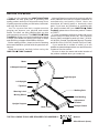
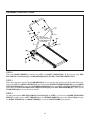
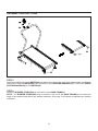
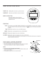
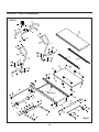
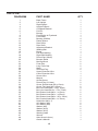
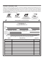
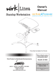
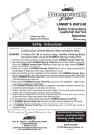
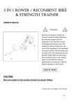
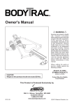
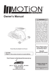
Owner's Manual
WARNING
Exercise can present a health
risk. Consult a physician
before beginning any exercise
program with this equipment.
If you feel faint or dizzy,
immediately discontinue use
of this equipment. Serious
bodily injury can occur if this
equipment is not assembled
and used correctly. Serious
bodily injury can also occur if
all instructions are not
followed. Keep others and
pets away from equipment
when in use. Always make
sure all bolts and nuts are
tightened prior to each use.
Follow all safety instructions in
this manual.
When calling for parts or
service, please specify the
following number.
CAUTION:
Weight on this product should not exceed 250 lbs.
45-1003
STAMINA PRODUCTS
MADE IN CHINA
Product May Vary Slightly
From Pictured.
This Product is Produced Exclusively by
2040 N. Alliance, Springfield, MO 65803
Customer Service
1 (800) 375-7520
2008, 06
www.staminaproducts.com
2008 Stamina Products, Inc.
TABLE OF CONTENTS
Page
Safety Instructions
Before You Begin
Equipment Warning & Notice Labels
Hardware Identification Chart
Assembly Instructions
Using The Electronics Meter
Treadmill Adjustments
Page
2
4
5
6
7
10
11
Maintenance
Storage
Product Parts Drawing
Parts List
Warranty
Notes
Fax/Mail Ordering Form
12
13
14
15
16
17
18
SAFETY INSTRUCTIONS
WARNING: To reduce the risk of serious injury, read the following Safety Instructions before
using the INMOTION T3000 Treadmill.
1. Read all warnings posted on the INMOTION T3000 Treadmill.
2. Read this Owner's Manual and follow it carefully before using the INMOTION T3000 Treadmill.
Make sure that it is properly assembled and tightened before use.
3. We recommend that two people be available for assembly of this product.
4. Keep children away from the INMOTION T3000 Treadmill. Do not allow children to use or play on
the INMOTION T3000 Treadmill. Keep children and pets away from the INMOTION T3000
Treadmill when it is in use.
5. It is recommended that you place this exercise equipment on an equipment mat.
6. Set up and operate the INMOTION T3000 Treadmill on a solid level surface. Do not position the
INMOTION T3000 Treadmill on loose rugs or uneven surfaces.
7. Inspect the INMOTION T3000 Treadmill for worn or loose components prior to use. Tighten/
replace any loose or worn components prior to using the INMOTION T3000 Treadmill.
8. Keep fingers clear of all pinch points when folding and unfolding the INMOTION T3000 Treadmill.
9. When folding the INMOTION T3000 Treadmill for storage, make sure that Base Frame Assembly
is locked securely in the folded position by the Pull Pin(6).
10. Consult a physician prior to commencing an exercise program. If, at any time during exercise, you
feel faint, dizzy, or experience pain, stop and consult your physician.
11. Follow your physician's recommendations in developing your own personal fitness program.
12. Always choose the workout which best fits your physical strength and flexibility level. Know your
limits and train within them. Always use common sense when exercising.
13. Do not wear loose or dangling clothing while using the INMOTION T3000 Treadmill.
14. Never exercise in bare feet or socks; always wear correct footwear, such as running, walking, or
crosstraining shoes. Be sure that they fit well, provide foot support and feature non-skid rubber soles.
15. Be careful to maintain your balance while using, mounting, dismounting, or assembling the
INMOTION T3000 Treadmill, loss of balance may result in a fall and serious bodily injury.
16. The INMOTION T3000 Treadmill should not be used by persons weighing over 250 pounds.
17. The INMOTION T3000 Treadmill should be used by only one person at a time.
18. The INMOTION T3000 Treadmill is for consumer use only. It is not for use in public or semipublic
facilities.
WARNING: Before starting any exercise or conditioning program you should consult with your personal
physician to see if you require a complete physical exam. This is especially important if you
are over the age of 35, have never exercised before, are pregnant, or suffer from any
illness. READ AND FOLLOW THE SAFETY PRECAUTIONS. FAILURE TO FOLLOW
THESE INSTRUCTIONS CAN RESULT IN SERIOUS BODILY INJURY.
2
CALL US FIRST
Customer Service
1(800) 375-7520
www.staminaproducts.com
THANK YOU FOR PURCHASING THE
INMOTION T3000 TREADMILL
To help you get started, we have pre-assembled most of your
INMOTION T3000 Treadmill at the factory with the exception
of those few parts left unassembled for shipping purposes.
Simply follow the few assembly instructions set forth in this manual.
With regular workouts you will be getting your body into shape
and on your way to achieving a happier and healthier lifestyle.
Should you have any questions,
please call our Customer Service Department toll-free number,
1 (800) 375-7520
Monday - Thursday, 7:30 A.M. - 5:00 P.M., Central Time.
Friday, 8:00 A.M. - 3:00 P.M., Central Time.
TELEPHONE
FAX
ONLINE
MAIL
CUSTOMER SERVICE
Tel: 1 (800) 375-7520
CUSTOMER SERVICE
Fax: (417) 889-8064
CUSTOMER SERVICE
[email protected]
[email protected]
www.staminaproducts.com
STAMINA PRODUCTS, INC.
ATTN: Customer Service
P.O. Box 1071
Springfield, MO. 65801-1071
3
BEFORE YOU BEGIN
Thank you for choosing the INMOTION T3000
Treadmill. We take great pride in producing this
quality product and hope it will provide many hours
of quality exercise to make you feel better, look better
and enjoy life to its fullest.
Yes, it's a proven fact that a regular exercise
program can improve your physical and mental
health. Too often, our busy lifestyles limit our time
and opportunity to exercise. The INMOTION T3000
Treadmill provides a convenient and simple method
to begin your assault on getting your body in shape
and achieving a happier and healthier lifestyle.
Before reading further, please review the drawing
below and familiarize yourself with the parts that are
labeled.
Read this manual carefully before using the
INMOTION T3000 Treadmill.
Although Stamina constructs its products with the
finest materials and uses the highest standards of
manufacturing and quality control, there can
sometimes be missing parts or incorrectly sized
parts. If you have any questions or problems with
the parts included with your INMOTION T3000
Treadmill, please do not return the product. Contact
us FIRST!
If a part is missing or defective, please call us toll
free at 1-800-375-7520 (in the U.S.). Our Customer
Service Staff is available to assist you from 7:30 A.M.
to 5:00 P.M. (Central Time) Monday through Thursday
and 8:00 A.M. to 3:00 P.M. (Central Time) on Friday.
If you would like to contact us online, go to our
website at www.staminaproducts.com and access the
Customer Service section.
Be sure to have the name and model number of
the product available when you contact us.
Meter
U-Shaped Handrail
Right Upright
Left Upright
Flywheel
Walking Belt
Warning Label
Moving Wheel
Side Molding
Adjustment
Bracket
Upright Support
Base Frame
THE FOLLOWING TOOLS ARE REQUIRED FOR ASSEMBLY :
Bumper Stand
Wrench
Allen Wrench (4mm)
4
EQUIPMENT WARNING & NOTICE LABELS
This chart is provided to help identify the warning & notice labels on the INMOTION
Please take a moment to familiarize yourself with all of the warning & notice labels.
Label is larger than actual size
W1
WARNING LABEL(46)
5
T3000 Treadmill.
HARDWARE IDENTIFICATION CHART
This chart is provided to help identify the hardware used in the assembly process. Place the washers, the
ends of the bolts, or screws on the circles to check for the correct diameter. Use the small scale to check the
length of the bolts and screws.
3/16"
1/4"
5/16"
3/8"
1/2"
INCHES
0
1/2
1
1/2
2
1/2
3
1/2
4
1/2
5
1/2
6
in.
mm.
0
10
20
30
40
50
60
70
80
90
100 110 120
130 140 150
MILLIMETERS
6
8
10
length
12
NOTICE: The length of all bolts and screws except those with flat heads is
measured from below the head to the end of the bolt or screw.
Flat head bolts and screws are measured from the top of the
head to the end of the bolt or screw.
length
After unpacking the unit, open the hardware bag and make sure that you have all the following items.
Some hardware may be already attached to the part.
Part No. and Description
Qty
34
Bolt, Hex Head (M8x1.25x15mm)
4
35
Bolt, Hex Head (M12x1.75x75mm)
2
36
Bolt, Button Head (M6x1x15mm)
2
41
42
Arc Washer (M6)
Arc Washer (M8)
2
4
45
Washer (M12)
2
6
ASSEMBLY INSTRUCTIONS
Place all parts from the box in a cleared area and position them on the floor in front of you. Remove all
packing materials from your area and place them back into the box. Do not dispose of the packing materials
until assembly is completed. Read each step carefully before beginning. If you are missing a part please call
our toll-free number for assistance 1 (800) 375-7520 or e-mail us at:
[email protected]
STEP 1
NOTE: The LEFT UPRIGHT(2) is the one with the LOWER EXTENSION WIRE(27).
Attach the LEFT and RIGHT UPRIGHTS(2, 3) to the UPRIGHT SUPPORT(4) with HEX BOLTS
(M8x1.25x15mm)(34) and ARC WASHERS(M8)(42).
7
ASSEMBLY INSTRUCTIONS
Slide down the
upper parts of the
FOAM GRIPS(22)
for assembly.
STEP 2
Place the BASE FRAME(1) between the LEFT and RIGHT UPRIGHTS(2, 3) and secure with HEX
BOLTS(M12x1.75x75mm)(35) and WASHERS(M12)(45). DO NOT TIGHTEN COMPLETELY.
STEP 3
Slide down the upper parts of the FOAM GRIPS(22), so you can see the screw holes at the back side of the
tops of the LEFT and RIGHT UPRIGHTS(2, 3). Connect the UPPER EXTENSION WIRE(26) to the LOWER
EXTENSION WIRE(27). Insert the U-SHAPED HANDRAIL(5) into the LEFT and RIGHT UPRIGHTS(2, 3)
and secure with BUTTON HEAD BOLTS(M6x1x15mm)(36) and ARC WASHERS(M6)(41). Slide up the
FOAM GRIPS(22) to cover the screw heads.
STEP 4
Go back and tighten HEX BOLTS(M12x1.75x75mm)(35) in STEP 2. Connect the LOWER EXTENSION
WIRE(27) located on the LEFT UPRIGHT(2) to the SENSOR WIRE(28). Insert the PULL PIN(6) through
the RIGHT UPRIGHT(3) and BASE FRAME(1) to lock the BASE FRAME(1) in position.
8
ASSEMBLY INSTRUCTIONS
STEP 5
Install two AA batteries into the METER(24), two batteries included. See page 10 for detailed battery installation
instructions. Slide the METER(24) onto the plate on the U-SHAPED HANDRAIL(5). Connect the UPPER
EXTENSION WIRE(26) to the METER(24).
STEP 6
Attach the BUMPER STANDS(20) to the bottom of the BASE FRAME(1).
NOTE: The BUMPER STANDS(20) may be stored on the end of the BASE FRAME(1) to increase the
angle of the treadmill and reduce the walking resistance. See page 12 for details on adjusting the walking
resistance.
9
USING THE ELECTRONIC METER
POWER ON : Walking Belt movement or push the button.
POWER OFF : Automatic shut off after 4 minutes of inactivity.
MODE / CLEAR BUTTON:
Press and release to select functions.
Press and hold for three seconds to reset all
functions to zero.
FUNCTIONS:
SCAN: Automatically scans TIME, SPEED, DISTANCE, and CALORIES in sequence with a change
every four seconds. Press and release the button until " " appears on the display and points
to SCAN.
TIME: Displays the time from 1 sec. up to 99:59 minutes.
SPEED: Displays the current speed from zero to 999.9 Mile/Hr.
DISTANCE: Displays the distance from zero to 99.99 miles.
CALORIES: Displays the calorie consumption, from zero to 999.9 Kcal.
The calorie readout is an estimate for an average user. It should be used only as a comparison
between workouts on this unit.
AA Batteries
HOW TO INSTALL AND REPLACE BATTERY:
1. Open the Battery Door on the back of the meter.
2. The meter operates with two AA batteries, two batteries included.
Refer to the illustration to install or replace the batteries.
NOTE:
1. Do not mix a new battery with an old battery.
2. Use the same type of battery. Do not mix an alkaline battery with
another type of battery.
3. Rechargeable batteries are not recommended.
10
TREADMILL ADJUSTMENTS
The basic idea behind the manual treadmill is to have the belt running on a treadmill board and between two
rollers so that the belt will move without much effort. In order for the belt to run smoothly, there are a few
points that need to be noted.
BELT ALIGNMENT
The belt must be in the center of the treadmill to prevent it from rubbing against the flywheels. If the belt rubs
a flywheel, it will be difficult to keep the belt moving and eventually damage the edge of the belt.
The treadmill has belt guides welded to the bottom of the treadmill frame that move the belt toward the
center of the treadmill. However, the rear roller must be properly aligned with the treadmill frame and front
roller if the belt is to remain centered on the treadmill.
The bolts in the rear of the treadmill (one on the left and the other on the right) adjust the alignment of the
rear roller as well as the tension of the belt.
The belt will run to the side of the loose rear bolt.
Hint: Eyeball the rear roller to make sure both the right side and the left side of the roller are the same
distance from the back edge of the treadmill. Use the 4mm ALLEN WRENCH to make these
adjustments. Turn the bolts Clockwise to tighten and Counter-Clockwise to loosen.
BELT DRIFTING LEFT
Turn the left screw 1/4 turn CLOCKWISE and the right screw 1/4 turn
COUNTER-CLOCKWISE, then walk on the treadmill. Repeat if needed.
BELT DRIFTING RIGHT
FT NT
LE TME
S
JU
AD
Turn the left screw 1/4 turn COUNTER-CLOCKWISE and the right screw
1/4 turn CLOCKWISE, then walk on the treadmill. Repeat if needed.
HT NT
RIG TME
S
JU
AD
NOTE:
When you believe the WALKING BELT is centered, use the treadmill for three (3) minutes to verify the
WALKING BELT won't drift to one side. If the WALKING BELT continues to drift, the floor may not be level.
Rotate the treadmill 90 degrees or move the treadmill to another location.
BELT TENSION
The belt should be tight and not lying on the treadmill board. If the belt is too loose, the belt will slip on the
front roller and you will notice a jerky movement when you walk on the treadmill. If the belt is too tight, the
edges of the belt will begin to curl and more effort will be required to move the belt. Excessive belt tension
can also damage the bearings in the rollers. The bolts in the rear of the treadmill (one on the left and the
other on the right) adjust the tension of the belt as well as the alignment of the rear roller.
BELT TOO LOOSE: Use the 4mm ALLEN WRENCH to tighten the bolts in the rear of the treadmill.
Tighten both rollers 1/4 turn at a time until the belt stops slipping on the front roller.
BELT TOO TIGHT: Use the 4mm ALLEN WRENCH to loosen the bolts in the rear of the treadmill. Loosen
both rollers 1/2 turn at a time until the belt begins to slip on the front roller. Then use the procedure above to
tighten the belt.
11
TREADMILL ADJUSTMENTS
WALKING RESISTANCE
The walking resistance or effort needed to push the treadmill belt can be adjusted by changing the incline
angle. This treadmill has two adjustment positions.
Highest Resistance
The BUMPER STANDS(20) are attached to
the bottom of the treadmill.
Lowest Resistance
Remove (unscrew) the BUMPER STANDS(20)
from the bottom of the treadmill and store them
in the end of the treadmill.
NOTE:
1. Since this is a new machine, you may need some time to get used to walking on the treadmill and to
break it in.
2. If the walking resistance is still too high, check the BELT TENSION.
3. The belt resistance can be reduced by adding silicone lubricant between the belt and the board. Wipe
the board under the belt with a cloth and spray or spread silicone lubricant on the board under the belt.
MAINTENANCE
The safety and integrity designed into the INMOTION T3000 Treadmill can only be maintained when the
INMOTION T3000 Treadmill is regularly examined for damage and wear. Special attention should be
given to the following:
1. Clean the exposed surfaces of the walking belt and the board with an absorbent cloth.
2. It is the sole responsibility of the user/owner to ensure that regular maintenance is performed.
3. Verify that all nuts and bolts are present and properly tightened. Replace missing nuts and bolts. Tighten
loose nuts and bolts.
4. Verify that the Warning Label is in place and easy to read. Call Stamina Products immediately
(1-800-375-7520) for a replacement Warning Label if the Warning Label is missing or damaged.
5. Worn or damaged components shall be replaced immediately or the INMOTION T3000 Treadmill
removed from service until repair is made.
6. Only Stamina Products supplied components shall be used to maintain/repair the INMOTION T3000
Treadmill.
7. Keep your INMOTION T3000 Treadmill clean by wiping with an absorbent cloth after use.
8. If the WALKING BELT(15) does not move easily, lubricate the BOARD(16) under the WALKING BELT(15)
with Silicone Lubricant.
12
STORAGE
1. To store the INMOTION T3000 Treadmill simply keep it in a clean dry place.
2. To avoid damage to the electronics meter, remove the batteries before storing the INMOTION T3000
Treadmill for one year or more.
3. Follow the following process to fold The INMOTION T3000 Treadmill as illustrated for easy storage.
a. Remove the PULL PIN(6) to unlock the BASE FRAME ASSEMBLY(1).
b. Fold up the BASE FRAME ASSEMBLY(1). Insert the PULL PIN(6) into the hole in the BASE FRAME
ASSEMBLY(1) to lock the BASE FRAME ASSEMBLY(1) in upright position.
CAUTION: Make sure the BASE FRAME ASSEMBLY(1) is locked securely in folded position by the
PULL PIN(6).
4. Move the INMOTION T3000 Treadmill with the moving wheels on the UPRIGHT SUPPORT(4). Grasp
the U-SHAPED HANDRAIL(5) to move the INMOTION T3000 Treadmill.
UNFOLD THE INMOTION T3000 Treadmill
a. Remove the PULL PIN(6) from the BASE FRAME ASSEMBLY(1) and unfold the BASE FRAME
ASSEMBLY(1).
b. Lock the BASE FRAME ASSEMBLY(1) in position by inserting the PULL PIN(6) through the RIGHT
UPRIGHT FRAME(3) and BASE FRAME(1).
13
PRODUCT PARTS DRAWING
FRONT
Belt Guides
BACK
14
PARTS LIST
DIAGRAM#
1
2
3
4
5
6
7
8
9
10
11
12
13
14
15
16
17
18
19
20
21
22
23
24
25
26
27
28
29
30
31
32
33
34
35
36
37
38
39
40
41
42
43
44
45
46
47
48
49
PART NAME
Base Frame
Left Upright
Right Upright
Upright Support
U-Shaped Handrail
Pull Pin
Bumper
Front Roller /w Flywheels
Front Shaft
Bearing (6000zz)
Plastic Spacer
Rear Roller
Rear Shaft
Adjustment Bracket
Walking Belt
Board
Left Side Molding
Right Side Molding
Round Cap (38mm)
Bumper Stand
Moving Wheel
Foam Grip
Long Foam Grip
Meter
Grommet Plug
Upper Extension Wire
Lower Extension Wire
Sensor Wire
Magnet
Screw Sleeve
Round Plug (31.8mm)
Screw, Round Head (M3 x 15mm)
Screw, Flat Head (M5 x 25mm)
Bolt, Hex Head (M8 x 1.25 x 15mm)
Bolt, Hex Head (M12 x 1.75 x 75mm)
Bolt, Button Head (M6 x 1 x 15mm)
Bolt, Button Head (M6 x 1 x 55mm)
Bolt, Button Head (M8 x 1.25 x 15mm)
Bolt, Socket Head (M6 x 1 x 70mm)
Nylock Nut (M6 x 1)
Arc Washer (M6)
Arc Washer (M8)
Washer (M6)
Washer (M10)
Washer (M12)
Warning Label
Wrench
Allen Wrench (4mm)
Owner's Manual
15
QTY
1
1
1
1
1
1
1
1
1
4
4
1
1
2
1
1
1
1
2
2
2
2
2
1
2
1
1
1
1
6
2
2
6
4
2
2
2
2
2
2
2
6
6
2
2
1
1
1
1
LIMITED WARRANTY
MODEL 45-1003
WARRANTY
Stamina Products, Inc. warrants that this product will be free from defects in materials and workmanship
under normal use, service and proper operation for a period of 90 days on the parts and one year on the
frame from the date of the original purchase from an authorized retailer. THIS WARRANTY SHALL NOT
APPLY TO ANY PRODUCT WHICH HAS BEEN SUBJECT TO COMMERCIAL USE, ABUSE, MISUSE,
ALTERATION OF ANY TYPE OR CAUSE OR TO ANY DEFECT OR DAMAGE CAUSED BY REPAIR,
REPLACEMENT, SUBSTITUTION OR USE WITH PARTS OTHER THAN PARTS PROVIDED BY STAMINA
PRODUCTS, INC. Commercial use includes use of the product in athletic clubs, health clubs, spas,
gymnasiums, exercise facilities, and other public or semipublic facilities whether or not the product's use is
in furtherance of a profit making enterprise, and all other use which is not for personal, family, or household
purposes.
To implement this limited warranty, send a written notice stating your name, date, and place of purchase and
a brief description of the defect along with your receipt to Stamina Products, Inc. P.O. Box 1071, Springfield
Missouri, USA, 65801-1071, or email us at [email protected], or call us at
1 (800) 375-7520. If the defect is covered under this limited warranty, you will be requested to return the
product or part to us for free repair or replacement at our option. NO ACTION FOR BREACH OF THIS
LIMITED WARRANTY MAY BE COMMENCED MORE THAN ONE (1) YEAR AFTER THE DATE THE
ALLEGED BREACH WAS OR SHOULD HAVE BEEN DISCOVERED. NO ACTION FOR BREACH OF
ANY IMPLIED WARRANTY MAY BE COMMENCED MORE THAN ONE (1) YEAR AFTER DELIVERY OF
THE PRODUCT TO THE PURCHASER. This limited warranty is not transferable. IF ANY PART OF THE
PRODUCT IS NOT IN COMPLIANCE WITH THIS LIMITED WARRANTY OR ANY IMPLIED WARRANTY,
THE REMEDY OF REPAIR OR REPLACEMENT IS THE EXCLUSIVE REMEDY AVAILABLE TO YOU. In
the event that the purchaser makes any claim under this limited warranty or any implied warranty, the Warrantor
reserves the right to require the product to be returned for inspection, at the purchaser's expense, to the
Warrantor's premises in Springfield, Missouri. Return of the enclosed warranty registration card is not
required for warranty coverage, but is merely a way of establishing the date and place of purchase.
Stamina Products, Inc. SHALL NOT BE LIABLE FOR THE LOSS OF USE OF ANY PRODUCT, LOSS OF
TIME, INCONVENIENCE, COMMERCIAL LOSS OR ANY OTHER INDIRECT, CONSEQUENTIAL,
SPECIAL OR INCIDENTAL DAMAGES DUE TO BREACH OF THE ABOVE WARRANTY OR ANY IMPLIED
WARRANTY.
This limited warranty is the only written or express warranty given by Stamina Products, Inc. This warranty
gives you specific legal rights, and you may also have other legal rights which vary from state to state.
ANY OTHER RIGHT WHICH YOU MAY HAVE, INCLUDING ANY IMPLIED WARRANTY OR
MERCHANTABILITY OR FITNESS FOR A PARTICULAR PURPOSE, IS LIMITED IN DURATION TO THE
DURATION OF THIS WARRANTY.
The laws in some jurisdictions restrict the rights of manufacturers and distributors of consumer goods to
disclaim or limit implied warranties and consequential and incidental damages with respect thereto. If any
such law is found to be applicable, the foregoing disclaimers and limitations of and on implied warranties and
consequential and incidental damages with respect thereto shall be disregarded and shall be deemed not to
have been made to the extent necessary to comply with such legal restriction.
16
NOTES
17
FAX/MAIL ORDERING FORM
Please do not return the product. For your convenience, Stamina's Customer Service Department can be
reached by email at [email protected] or toll free at 1-800-375-7520 (in the U.S.). Should a part
be missing or a defective part found, please call us from 7:30 A.M. to 5:00 P.M. Central Time, Monday
through Thursday and 8:00 A.M. to 3:00 P.M. on Friday or fill out the fax sheet ordering form below and fax
it to (417) 889-8064. Our Customer Service Department will be able to assist you with your problem and the
part will be mailed directly to your house.
TELEPHONE
FAX
ONLINE
MAIL
CUSTOMER SERVICE
Tel: 1 (800) 375-7520
CUSTOMER SERVICE
Fax: (417) 889-8064
CUSTOMER SERVICE
[email protected]
[email protected]
www.staminaproducts.com
STAMINA PRODUCTS, INC.
ATTN: Customer Service
P.O. Box 1071
Springfield, MO. 65801-1071
Detach and Mail or Fax the Form Below
Stamina Products, Inc.
P.O. Box 1071
Springfield, MO 65801-1071
Mr./Ms:
Address:
City:
Apt. #:
Zip Code:
State:
IMPORTANT : We must have your phone number in order to process the order!
Phone #: (
)
Date Purchased:
Model #:
Purchased From:
Work Phone #: (
)
IMPORTANT : Before filling out the form below make sure you have the right information.
Refer to the parts list to make sure you're ordering the right parts!
EXAMPLE:
PART #
DESCRIPTION
QUANTITY
1
Rear Unit Assembly
1