1
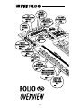
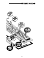
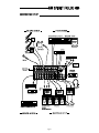
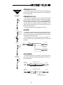
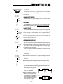
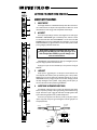
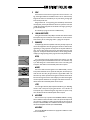
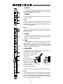
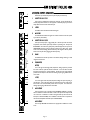
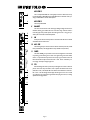
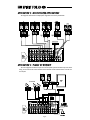
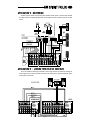
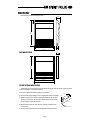
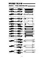
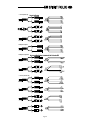
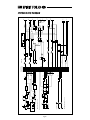
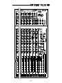
A Harman International Company PAGE 15 PAGE 15 PAGE 14 PAGE 15 PAGE 9 PAGE 9/12 PAGE 9 PAGE 9 PAGE 10 PAGE 10 PAGE 10 PAGE 11 Page 1 PAGE 14 PAGE 14 PAGE 15 PAGE 11 Page 2 INTRODUCTION Thank you for purchasing a SPIRIT FOLIO SX mixer, brought to you with pride by the SPIRIT team of Andy, Colin, Chris, James, Simon, Mukesh, Graham, Martin, Paul, Matt and Peter, with the support of many others - we hope you will have as much fun using it! Owning a SPIRIT console brings you the expertise and support of one of the industrys leading manufacturers and the results of over 23 years experience supporting some of the biggest names in the business. Built to the highest standards using quality components and new surface mount technology, FOLIO SX is designed to be as easy to use as possible, but some time spent NOW, looking through this manual and getting to know your new mixer will give you lots of helpful tips and confidence, away from the pressures of a live session. Dont be afraid to experiment to find out how each control affects the sound - this will only extend your creativity and help you to get the best from your mixer. Installation and Safety Precautions Installing the Mixer C orrect connection and positioning of your mixer is important for successful and trouble-free operation. The following sections are intended to give guidance with cabling, connections and configuration of your mixer. o Choose the mains supply for the sound system with care, and do not share sockets or earthing with lighting dimmers. o Position the mixer where the sound can be heard clearly. o Run audio cables separately from dimmer wiring, using balanced lines wherever possible. If necessary, cross audio and lighting cables at right angles to minimise the possibility of interference. Keep unbalanced cabling as short as possible. o Check your cables regularly and label each end for easy identification. SAFETY PRECAUTIONS For your own safety and to avoid invalidation of the warranty please read this section carefully. The FOLIO SX mixer must only be connected through the Power Supply supplied. The wires in the mains lead are coloured in accordance with the following code: Earth: Green and Yellow (Green/Yellow - US) Neutral: Blue (White - US) Live: (Black - US) Brown As the colours of the wires in the mains lead may not correspond with the coloured markings identifying the terminals in your plug, proceed as follows: The wire which is coloured Green and Yellow must be connected to the terminal in the plug which is marked with the letter E or by the earth symbol. The wire which is coloured Blue must be connected to the terminal in the plug which is marked with the letter N. The wire which is coloured Brown must be connected to the terminal in the plug which is marked with the letter L. Ensure that these colour codings are followed carefully in the event of the plug being changed. To avoid the risk of fire, replace the mains fuse only with the correct value fuse, as indicated on the power supply. Page 3 CONNECTING IT UP Page 4 WIRING UP Please refer to pages 27/28 for additional wiring details. Balanced Mic XLR 2. Hot(+ve) 3. Cold(-ve) 1. Screen Unbalanced Mic XLR 2. Hot(+ve) Link 3 to 1 1. Screen Balanced 3 pole Jack Unbalanced 3 pole Jack Hot (+ve) Cold (-ve) Gnd/Screen Signal Gnd/Screen Gnd/Screen Tip The mic input accepts XLR-type connectors and is designed to suit a wide range of BALANCED or UNBALANCED low-level signals, whether from delicate vocals requiring the best low-noise performance or close-miked drum kits needing maximum headroom. Professional dynamic, condenser or ribbon mics are best because these will be LOW IMPEDANCE. While you can use low-cost HIGH IMPEDANCE mics, you do not get the same degree of immunity to interference on the microphone cable and as a result the level of background noise may be higher. If you turn the PHANTOM POWER on, the socket provides a suitable powering voltage for professional condenser mics. DO NOT use UNBALANCED sources with the phantom power switched on. The voltage on pins 2 & 3 of the XLR connector may cause serious damage. BALANCED dynamic mics may normally be used with phantom power switched on (contact your microphone manufacturer for guidance). The input level is set using the input SENS knob. The LINE input offers the same gain range as the MIC input, but at a higher input impedance. This is suitable for most line level sources, and provides the gain needed for lower level keyboards and high impedance microphones. WARNING - Start with the input SENS knob turned fully anticlockwise when plugging high level sources into the LINE input to avoid overloading the input channel or giving you a very loud surprise! LINE INPUT Ring Sleeve Inserts Signal Send Signal Return Gnd/Screen Tip Ring MIC INPUT Sleeve Accepts 3-pole `A gauge jacks, or 2-pole mono jacks which will automatically ground the cold input. Use this input for sources other than mics, such as keyboards, drum machines, synths, tape machines or guitars. The input is BALANCED for low noise and immunity from interference, but you can use UNBALANCED sources by wiring up the jacks as shown, although you should then keep cable lengths as short as possible to minimise interference pick-up on the cable. Note that the ring must be grounded if the source is unbalanced. Set the input level using the SENS knob, starting with the knob turned fully anticlockwise. Unplug any MIC connection when using the LINE input. INSERT POINT The unbalanced, pre-EQ insert point is a break in the channel signal path, allowing limiters, compressors, special EQ or other signal processing units to be added in the signal path. The Insert is a 3-pole A gauge jack socket which is normally bypassed. When a jack is inserted, the signal path is broken, just before the EQ section. The signal from the channel appears on the TIP of the plug and is returned on the RING, with the sleeve as a common ground. The Send may be tapped off as an alternative pre-fade, pre-EQ direct output if required, using a lead with tip and ring shorted together so that the signal path is not interrupted. Page 5 STEREO INPUTS 13/14 & 17/18 These accept RCA phono jacks to allow easy connection to hi-fi equipment or DAT players. The input is unbalanced, and ideal for pre-show music sources or signals that do not require any EQ or effects. Mix & Sub Outputs Aux Outputs Mono Output Signal + Signal Screen STEREO INPUTS 15/16 & 19/20 These accept 3-pole `A gauge jacks, or 2-pole mono jacks which will automatically ground the cold input. Use these inputs for sources such as keyboards, drum machines, synths, tape machines or as returns from processing units. The input is BALANCED for low noise and immunity from interference, but you can use UNBALANCED sources by wiring up the jacks as shown, although you should then keep cable lengths as short as possible to minimise interference pick-up on the cable. Note that the ring must be grounded if the source is unbalanced. Mono sources can be fed to both paths by plugging into the Left jack only. Mix Inserts Signal Send Signal Return Gnd/Screen Tip Ring Sleeve MIX INSERTS The unbalanced, pre-fade Mix insert point is a break in the output signal path to allow the connection of, for example, a compressor/limiter or graphic equaliser. The Insert is a 3-pole A gauge jack socket which is normally bypassed. When a jack is inserted, the signal path is broken, just before the mix fader. The mix signal appears on the TIP of the plug and is returned on the RING. A Y lead may be required to connect to equipment with separate send and return jacks as shown below: Signal Send Headphones Send to External Device Insert Point Left Signal Right Signal Ground Screen Signal Return Note: If XLRs are used, join Pins 1 & 3 and connect to cable screen. Connect Pin 2 to signal. Return from External Device MIX & SUB OUTPUTS Monitor Outputs Direct Outputs Signal Ground Ground The MIX and SUB outputs are on 3-pole 3-pole A gauge jack sockets, wired as shown, and incorporate impedance balancing, allowing long cable runs to balanced amplifiers and other equipment. From FOLIO SX Impedance Balanced Output Signal Screen From FOLIO SX Impedance Balanced Output Signal Screen (a) Balanced Connection To External Device Signal Ground (b) Unbalanced Connection To External Device Signal Ground Experience has shown that sometimes it is better not to connect screen at external device end. Page 6 AUX OUTPUTS The Aux outputs are on 3-pole A gauge jack sockets, wired as shown on the left, and incorporate impedance balancing, allowing long cable runs to balanced amplifiers and other equipment. Mix & Sub Outputs Aux Outputs Mono Output Signal + Signal Screen CHANNEL DIRECT OUTPUTS The Direct outputs are on 3-pole A gauge jack sockets, wired as shown on the left, and are unbalanced. HEADPHONES The PHONES output is a 3-pole A gauge jack, wired as a stereo output as shown, suitable for headphones of 200W or greater. 8W headphones are not recommended. Polarity (PHASE) Mix Inserts Signal Send Signal Return Gnd/Screen Tip Ring Sleeve You will probably be familiar with the concept of polarity in electrical signals and this is of particular importance to balanced audio signals. Just as a balanced signal is highly effective at cancelling out unwanted interference, so two microphones picking up the same signal can cancel out, or cause serious degradation of the signal if one of the cables has the +ve and -ve wires reversed. This phase reversal can be a real problem when microphones are close together and you should therefore take care always to connect pins correctly when wiring audio cables. Grounding and Shielding Headphones Left Signal Right Signal Ground For optimum performance use balanced connections where possible and ensure that all signals are referenced to a solid, noise-free earthing point and that all signal cables have their screens connected to ground. In some unusual circumstances, to avoid earth `loops ensure that all cable screens and other signal earths are connected to ground only at their source and not at both ends. If the use of unbalanced connections is unavoidable, you can mimimise noise by following these wiring guidelines: l On INPUTS, unbalance at the source and use a twin, screened cable as though it were balanced. Monitor Outputs Direct Outputs Signal Ground Ground l On OUTPUTS, connect the signal to the +ve output pin, and the ground of the output device to -ve. If a twin screened cable is used, connect the screen only at the mixer end. l Avoid running audio cables or placing audio equipment, close to thyristor dimmer units or power cables. l Noise immunity is improved significantly by the use of low impedance sources, such as good quality professional microphones or the outputs from most modern audio equipment. Avoid cheaper high impedExample 1 ance microphones, which may suffer Audio (with ground connected) Mixer Amplifier from interference over long cable runs, even with well-made cables. Supply Earth Loop Supply l Grounding and shielding is still seen as a black art, and the suggestions above are only guidelines. If your system still hums, an earth loop is the most likely cause. Two examples of how an earth loop can occur are shown on the right Page 7 Mains Earth Example 2 Left Signal (with ground connected) Mixer Earth Loop Right Signal (with ground connected) Amplifier Fault Finding Guide Repairing a sound mixing console requires specialist skills, but basic Fault Finding is within the scope of any user if a few basic rules are followed. l Get to know the Block Diagram of your console (see page 29). l Get to know what each component in the system is supposed to do. l Learn where to look for common trouble spots. The Block Diagram is a representative sketch of all the components of the console, showing how they connect together and how the signal flows through the system. Once you have become familiar with the various component blocks you will find the Block Diagram quite easy to follow and you will have gained a valuable understanding of the internal structure of the console. Each Component has a specific function and only by getting to know what each part is supposed to do will you be able to tell if there is a genuine fault! Many `faults are the result of incorrect connection or control settings which may have been overlooked. Basic Troubleshooting is a process of applying logical thought to the signal path through the console and tracking down the problem by elimination. l Swap input connections to check that the source is really present. Check both Mic and Line inputs. l Eliminate sections of the channel by using the insert point to re-route the signal to other inputs that are known to be working. l Route channels to different outputs or to auxiliary sends to identify problems on the Master section. l Compare a suspect channel with an adjacent channel which has been set up identically. Use PFL and AFL to monitor the signal in each section. Insert contact problems may be checked by using a dummy jack with tip and ring shorted together as shown below. If the signal appears when the jack is inserted it shows that there is a problem with the normalling contacts on the jack socket, caused by wear or damage, or often just dirt or dust. Keep a few in your gig tool box. Wire Link Dummy Insert Bypass Jack Page 8 GETTING TO KNOW YOUR CONSOLE 1 2 Mono Input Channel 1 The first eight channels have a dedicated Direct Output which allows direct connection to external devices, for example to feed Tape Machines or effects units. See the Advanced Features section on page 18 for a full explanation of these outputs. 3 4 DIRECT OUTPUT 2 MIC INPUT The mic input accepts XLR-type connectors and is designed to suit a wide range of BALANCED or UNBALANCED signals. Professional dynamic, condenser or ribbon mics are best because these will be LOW IMPEDANCE. You can use low-cost HIGH IMPEDANCE mics, but the level of background noise will be higher. If you turn the PHANTOM POWER on (top right-hand side of the mixer) the socket provides a suitable powering voltage for professional condenser mics. 5 6 ONLY connect condenser microphones with the +48V powering OFF, and ONLY turn the +48V powering on or off with all output faders DOWN, to prevent damage to the mixer or external devices. 7 TAKE CARE when using unbalanced sources, which may be damaged by the phantom power voltage on pins 2 & 3 of the XLR connector. Unplug any mics if you want to use the LINE Input. The input level is set using the SENS knob. 8 3 Accepts 3-pole `A gauge (TRS) jacks. Use this input for sources other than mics, such as keyboards, drum machines, synths, tape machines or guitars. The input is BALANCED for low noise and top quality from professional equipment, but you can use UNBALANCED sources by wiring up the jacks as shown below, although you should then keep cable lengths as short as possible. Unplug anything in the MIC input if you want to use this socket. Set the input level using the SENS knob. 9 10 11 LINE INPUT 4 INSERT POINT (ALTERNATIVE DIRECT SEND) 12 The unbalanced, pre-EQ insert point is a break in the channel signal path, allowing limiters, compressors, special EQ or other signal processing units to be added in the signal path. The Insert is a 3-pole A gauge jack socket which is normally bypassed. When a jack is inserted, the signal path is broken, just before the EQ section. 13 The Send may be tapped off as an alternative pre-fade, pre-EQ direct output if required, using a lead with tip and ring shorted together so that the signal path is not interrupted (see below). Mono pre-fade Direct Send Signal Send Insert Point Wire Link 14 Screen RCA Phono centre Link pins 1 & 3 XLR XLR Screen 1 3 2 Signal Page 9 5 SENS This knob sets how much of the source signal is sent to the rest of the mixer. Too high, and the signal will distort as it overloads the channel. Too low, and the level of any background hiss will be more noticeable and you may not be able to get enough signal level to the output of the mixer. Setting the knob to the `U mark gives unity gain for the LINE input. Note that some sound equipment, particularly that intended for domestic use, operates at a lower level (-10dBV) than professional equipment and will therefore need a higher gain setting to give the same output level. See `Initial Set Up on page 16 to learn how to set SENS correctly. 6 dB Pressing this switch activates a steep 18dB per octave filter which reduces the level of bass frequencies only, and is a real bonus for a such a small mixer. Use this in live PA situations to clean up the mix, reducing stage rumble or `popping from microphones. 7 20 100Hz HI-PASS FILTER 100Hz Frequency/Hz EQUALISER The Equaliser (EQ) allows fine manipulation of the sound, particularly to improve the sound in live PA applications where the original signal is often far from ideal and where slight boosting or cutting of particular voice frequencies can really make a difference to clarity. There are three sections giving the sort of control usually only found on much larger mixers. The EQ knobs can have a dramatic effect, so use them sparingly and listen carefully as you change any settings so that you get to know how they affect the sound. 20k Muddiness & Rumble dB HF EQ HF 20 Frequency/Hz Turn to the right to boost high (treble) frequencies above 12kHz by up to 15dB, adding crispness to cymbals, vocals and electronic instruments. Turn to the left to cut by up to 15dB, reducing hiss or excessive sibilance which can occur with certain types of microphone. Set the knob in the centre-detented position when not required. 20k dB MID EQ MID 20 Frequency/Hz There are two knobs which work together to form a SWEPT MID EQ. The lower knob provides 15dB of boost and cut, just like the HF EQ knob, but the frequency at which this occurs can be set by the upper knob over a range of 240Hz to 6kHz. This allows some truly creative improvement of the signal in live situations, because this mid band covers the range of most vocals. Listen carefully as you use these controls together to find how particular characteristics of a vocal signal can be enhanced or reduced. Set the lower knob to the centre-detented position when not required. 20k dB LF LF EQ 20 Frequency/Hz Turn to the right to boost low (bass) frequencies below 60Hz by up to 15dB, adding warmth to vocals or extra punch to synths, guitars and drums. Turn to the left to cut low frequencies by up to 15dB for reducing hum, stage rumble or to improve a mushy sound. Set the knob to the centre-detented position when not required. 20k 8 AUX SENDS These are used to set up a separate mixes for FOLDBACK, EFFECTS or recording, and the combination of each the Aux Send is mixed to the respective Aux Output at the rear of the mixer. For Effects it is useful for the signal to fade up and down with the fader (this is called POST-FADE), but for Foldback or Monitor feeds it is important for the send to be independent of the fader (this is called PRE-FADE). AUX SEND 1 This is always PRE-FADE and therefore most appropriate for foldback or monitor mixes or external submix. Page 10 AUX SEND 2 This is normally POST-FADE, and would typically be used as an effects send, but may be switched globally to PRE-FADE using the POST/PRE switch on the Master section, providing a second foldback or monitor send if required. 1 AUX SEND 3 2 3 This is always POST-FADE for effects sends, external submix (or for Centre Voice cluster or mono Tape mix). 9 4 5 PAN This control sets the amount of the channel signal feeding the Right and Left MIX or SUB buses, allowing you to move the source smoothly across the stereo image. When the control is turned fully right or left you are able to route the signal at unity gain to either left or right outputs individually. 10 ON All outputs from the channel except inserts are muted when the ON switch is released and enabled when the switch is down, allowing levels to be pre-set before the before the signal is required. 6 11 MIX / SUB The channel signal may be routed to either the main MIX (switch UP) or SUB buses (switch DOWN). The left/right balance is set by the PAN control (see above) allowing the signal to be sent proportionately to any of the buses. 7 12 FADER The 100mm FADER, with a custom-designed law to give even smoother control of the overall signal level in the channel strip, allows precise balancing of the various source signals being mixed to the Master Section. You get most control when the input SENSITIVITY is set up correctly, giving full travel on the fader. See the `Initial Set Up section on page 16 for help in setting a suitable signal level. 8 13 DIRECT PRE/POST See Direct Output (1) and Advanced Features on page 18 for an explanation of the Direct Output. The output may be selected as either PRE or POST fader. The factory default setting is POST-FADER, but this may be changed by moving an internal switch as shown on the right. 9 10 11 Remove the protective grommet to gain access to the switch and move the switch carefully upwards using a small screwdriver or the end of a POST-FADE pencil. It is advisable to turn the unit off before making this adjustment. 12 13 PRE-FADE Always check all outputs after adjusting to ensure that switching has been successful. 14 14 PFL When the latching PFL switch is pressed, the pre-fade signal is fed to the headphones, control room output and meters, where it replaces the selected monitor source (MIX, SUB or 2TK). The PFL/AFL LED on the Master section illuminates to warn that a PFL is active. This is a useful way of listening to any required input signal without interrupting the main mix, for making adjustments or tracing problems. Page 11 1 STEREO INPUT CHANNEL Each stereo input channel comprises two pairs of inputs per channel strip: 1 INPUTS 13/14 & 17/18 These inputs are unbalanced on RCA phono connectors, and are intended for use with CD players, DAT machines or Hi-Fi equipment. Alternatively they may be used as simple effects returns or stereo instrument inputs. 4 2 LEVEL The LEVEL control sets the level of the channel signal. 2 3 The MIX/SUB switch allows the signal to be routed to either the main MIX (switch up) or SUB mix (switch down). 3 5 MIX/SUB 4 INPUTS 15/16 & 19/20 These inputs accept 3-pole `A gauge (TRS) jacks. Use these inputs for sources such as keyboards, drum machines, synths, tape machines or processing units. The inputs are BALANCED for low noise and top quality from professional equipment, but you can use UNBALANCED sources by wiring up the jacks as shown in the Wiring it Up section earlier in this manual, although you should then keep cable lengths as short as possible. Mono sources may be used by plugging into the left jack only. 6 5 GAIN The GAIN control sets the input level to the channel, allowing matching to a wide range of line level sources. 7 6 EQUALISER HF EQ Turn to the right to boost high (treble) frequencies, adding crispness to percussion from drum machines, synths and electronic instruments. Turn to the left to cut these frequencies, reducing hiss or excessive brilliance. Set the knob in the centre-detented position when not required. The control has a shelving response giving 15dB of boost or cut at 12kHz. 8 9 10 LF EQ Turn to the right to boost low (bass) frequencies, adding extra punch to synths, guitars and drums. Turn to the left to reduce hum, boominess or improve a mushy sound. Set the knob to the centre-detented position when not required. The control has a shelving response giving 15dB of boost or cut at 60Hz. 11 7 AUX SENDS These are used to set up a separate mixes for FOLDBACK, EFFECTS or recording, and the combination of each the Aux Send is mixed to the respective Aux Output at the rear of the mixer. For Effects it is useful for the signal to fade up and down with the fader (this is called POST-FADE), but for Foldback or Monitor feeds it is important for the send to be independent of the fader (this is called PRE-FADE). 12 AUX SEND 1 This is always PRE-FADE and therefore most appropriate for foldback or monitor mixes. Page 12 AUX SEND 2 1 This is normally POST-FADE, and would typically be used as an effects send, but may be switched globally to PRE-FADE using the POST/PRE switch on the Master section, providing a second foldback or monitor send if required. AUX SEND 3 4 This is always POST-FADE. 8 This control sets the amount of the channel signal feeding the Right and Left MIX or SUB buses, allowing you to balance the source in the stereo image. When the control is turned fully right or left you feed only that side of the signal to the mix. Unity gain is provided by the control in the centre-detented position. 2 3 BALANCE 9 ON All outputs from the channel except inserts are muted when the ON switch is released and enabled when the switch is down. 5 10 MIX / SUB The channel signal may be routed in stereo to either the main MIX (switch UP) or SUB buses (switch DOWN). The left/right balance is set by the BAL control (see above). 6 11 The 100mm FADER gives you smooth control of the overall signal level in the channel strip, allowing precise balancing of the various source signals being mixed to the Master Section. It is important that the input level is set correctly to give maximum travel on the fader which should normally be used at around the `0 mark. See the `Initial Set Up section on page 16 for help in setting the right level. 7 12 8 9 10 FADER PFL When the latching PFL switch is pressed, the pre-fade signal is fed in mono to the headphones, control room output and meters, where it replaces the selected monitor source (MIX, SUB or 2TK). The PFL/AFL LED on the Master section illuminates to warn that a PFL is active. The Left and Right meters display the PFL signal in mono. This is a useful way of listening to any required input signal without interrupting the main mix, for making adjustments or tracing problems. 11 12 Page 13 Master Section 1 1 2 3 4 Many professional condenser mics need PHANTOM POWER, which is a method of sending a powering voltage down the same wires as the mic signal. Press the switch to enable the +48V power to all of the MIC inputs. The adjacent LED illuminates when the power is active. TAKE CARE when using unbalanced mics which may be damaged by the phantom power voltage. Balanced dynamic mics can normally be used with phantom power switched on (contact your microphone manufacturer for guidance) Mics should always be plugged in, and all output faders set to minimum before switching the Phantom Power ON to avoid damage to external equipment 5 6 PHANTOM POWER 2 POWER INDICATOR This LED lights to show when power is connected to the console. 7 3 BARGRAPH METERS The three colour peak reading BARGRAPH METERS normally follow the Monitor selection to show the level of the MIX RIGHT and MIX LEFT outputs, giving you a constant warning of excessive peaks in the signal which might cause overloading. Aim to keep the signal just touching the amber segments at peak levels for best performance. 8 9 Similarly, if the output level is too low and hardly registering at all on the meters, the level of background noise may become significant. Take care to set up the input levels for best performance. 11 10 When any PFL switch is pressed, the meters switch to show the selected PFL signal on both meters, in mono. 4 2TK LEVEL The rotary control sets the level of the 2 Track Tape input, which is routed to the headphones, monitor outputs and meters. These inputs, on RCA phono connectors are an ideal to connect the playback of a tape machine for monitoring. 5 MIX/SUB When this switch is released the meters and headphones monitor the Mix signal. Alternatively, pressing the switch selects the SUB mix as the monitor source. 6 2TK Pressing the 2TK switch selects the 2TK input as the monitor source, instead of the MIX or SUB signal (see MIX/SUB above). 7 MONITOR & PHONES LEVEL This control sets the output level to the MONITOR LEFT & RIGHT outputs. If HEADPHONES are plugged into the PHNS jack the Monitor outputs are cut off, and the knob then sets the headphone listening level. When the PHONES are unplugged the Monitor output is restored. 8 AUX MASTERS Each Aux output has a master output level control and associated AFL switch. Page 14 AUX AFLs 1 2 3 4 Just like the PFL switches on the channels, you can monitor each AUX output by pressing the AFL switch. This routes the AUX output signal to the MONITOR or PHONES, replacing any existing signal (normally the Monitor receives either MIX, SUB or 2TK, see above). The METERS also switch from the selected source to display the PFL/AFL signal and the PFL/AFL LED lights to warn that a PFL or AFL switch is pressed. When you release the switch the Monitor swaps back to the previous source. AUX 2 POST/PRE The input channels provide both Pre- and Post-Fade AUX 2 sends which may be selected desk-wide on the Master Section. Press the POST/PRE switch to make all of the AUX 2 Sends on the channel strips PRE-FADE. This means that they will all be unaffected by the position of the channel faders, making them ideal for FOLDBACK or MONITORING. 5 6 7 When the switch is released the AUX 2 Sends are all POST-FADE, and will fade up and down with the channel faders. This is more suitable for effects sends which need to fade out with the associated source. 8 9 The Mix Left and Right signals are summed to a MONO output on a 3 pole A gauge jack. Output level is set by the dedicated rotary control. Monitoring of the Mono output, if required, but be done at the external equipment it feeds, or the signal brought back to a spare console input. 9 11 10 MONO SUM 10 MASTER FADERS The MASTER FADERS set the final level of the MIX and SUB outputs, and separate faders are provided for each output. These should normally be set close to the `0 mark if the input GAIN settings have been correctly set, to give maximum travel on the faders for smoothest control. 11 SUB TO MIX The SUB outputs may be used as independent outputs from the console, or used as true subgroups, routed to the main Mix outputs. When the switch is released the SUB signal feeds the SUB outputs only. With the switch pressed the post-fade Sub Left and Right signals are routed to Mix Left and Right respectively. The Sub outputs remain unaffected. Page 15 USING YOUR FOLIO SX CONSOLE T he final sound from your P.A. system can only ever be as good as the weakest link in the chain, and especially important is the quality of the source signal because this is the starting point of the chain. Just as you need to become familiar with the control functions of your mixer, so you must recognise the importance of correct choice of inputs, microphone placement and input channel settings. However, no amount of careful setting up can take account of the spontaneity and unpredictability of live performance and the mixer must be set up to provide `spare control range to compensate for changing microphone position and the absorption effect of a large audience (different acoustic characteristics from sound check to show). Microphone Placement Cardioid Response Hypercardioid Response Omnidirectional Response Careful microphone placement and the choice of a suitable type of microphone for the job is one of the essentials of successful sound reinforcement. The diagrams on the left show the different pick-up patterns for the most common types of microphone. Cardioid microphones are sensitive to sound coming from in front, and hypercardioid microphones offer even greater directivity, with a small amount of pickup behind the microphone. These types are ideal for recording vocalists or instruments, where rejection of unwanted sounds and elimination of feedback is important. The aim should be to place the microphone as close as physically possible to the source, to cut out unwanted surrounding sounds, allow a lower gain setting on the mixer and avoid feedback. Also a well-chosen and well-placed microphone should not need any appreciable equalisation. There are no exact rules - let your ears be the judge. In the end, the position that gives the desired effect is the correct position! Initial Set Up Once you have connected up your system (see the sections on connection and wiring earlier in this manual for guidance) you are ready to set initial positions for the controls on your mixer. The front panel drawing inside the rear cover shows typical initial control positions which may be found a useful guide to setting up the mixer for the first time. Set up individual input channel as follows: l Connect your sources (microphone, keyboard etc.) to the required inputs. Note: Phantom powered mics should be connected before the +48V is switched on. Route the channel to Mix. l Set Master faders at 0, input faders at 0, and set power amplifier levels to about 70%. l Provide a typical performance level signal and press the PFL button on the first channel, monitoring the level on the bargraph meters. l Adjust the input gain until the meter display is in the amber section, with occasional peaks to the first red LED at a typical maximum source level. This allows sufficient headroom to accommodate peaks and establishes the maximum level for normal operation (but see note below). Page 16 l Repeat this procedure on other channels as required. As more channels are added to the mix, the meters may move into the red section. Adjust the overall level using the Master Faders if necessary. l Listen carefully for the characteristic sound of `feedback. If you cannot achieve satisfactory input level setting without feedback, check microphone and speaker placement and repeat the exercise. If feedback persists, it may be necessary to use a Graphic Equaliser to reduce the system response at particular resonant frequencies. Note: The initial settings should only be regarded as a starting point for your mix. It is important to remember that many factors affect the sound during a live performance, for instance the size of the audience! You are now ready to start building the mix and this should be done progressively, listening carefully for each component in the mix and watching the meters for any hint of overload. If this occurs, back off the appropriate Channel Fader slightly until the level is out of the red segments, or adjust the Master Faders. Remember that the mixer is a mixer, not an amplifier. Increasing the overall level is the job of the amplifier, and if it is found impossible to provide adequate level, it is probable that the amplifier is too small for the application. Choose your amplifier carefully, and do not try to compensate for lack of power by using the mixer to increase output level. Note: The level of any source signal in the final output is affected by many factors, principally the Input Sensitivity control, Channel Fader, Sub and Mix Faders. You should try to use only as much microphone gain as required to achieve a good balance between signals, with the faders set as described above. If the input gain is set too high, the channel fader will need to be pulled down too far in compensation to leave enough travClipped el for successful mixing and there is a Signal greater risk of feedback because small fader movements will have a very significant effect on output level. Also Noise there will be a chance of distortion as the signal overloads the channel and If the signal level is too high, clipping distortion causes clipping. may occur. If the gain is set too low, you will not find enough gain on the faders to bring the signal up to an adequate level, and backgound hjiss will be more noticeable. Signal Noise This is illustrated on the right: If the signal level is too low it may be masked by the noise. Page 17 Advanced Features 1 DIRECT OUTPUT The Direct outputs on the first eight channels allow you to record signals direct to a multitrack tape machine. Normally they are set POST-FADER but can be changed to PRE-FADER by moving the internal PRE/POST switch (13) accessible through an aperture covered by a grommet beside the fader on channel 1 (see below). POST-FADE PRE-FADE In the POST-FADER position the outputs may be used as individual effects sends or to provide fader control of recording levels in a studio recording application. For live recording, the outputs would normally be set to PRE-FADE, so that the direct output levels remain unaffected by fader settings for the main PA mix. The direct output level may be monitored by pressing the PFL switch on the appropriate channel to feed the pre-fade signal to the monitors and the bargraph meters. In applications where more than 8 tracks are being created, the Direct outputs may be split to feed multiple tape tracks in blocks of 8, and individual tracks enabled on the recorder. Note also that the insert sends may also be used as an alternative pre-fade, pre-EQ direct output, using a lead with tip and ring shorted together so that the signal path is not interrupted. Refer to page 9 for an example. Page 18 USING THE FOLIO SX ON LOCATION The FOLIO SX may be powered from a DC source of 11-18V using the optional Portapower unit, for applications where a source of mains power is unavailable. Contact your dealer for further details, quoting Spirit Part No ZZ2849. Page 19 Application 1 - LIVE SOUND REINFORCEMENT This drawing shows a typical configuration for sound reinforcement with the main PA fed from Mix L & R, plus an additional centre fill fed from the Mono output. The Aux sends are used for foldback and effects, and Sub L & R are used to feed a recorder. In this case all channels would be routed to SUB, and SUB TO MIX pressed to routed all sources to SUB and MIX. Using Delay IN REINFORCEMENT SYSTEMS The drawing below illustrates how to calculate delay settings for fill speakers in multiple speaker installations. Page 20 APPLICATION 2 - MULTISPEAKER APPLICATIONS This configuration demonstrates how multiple speaker configurations can be driven by the FOLIO SX. APPLICATION 3 - PLACES OF WORSHIP This mono configuration uses the Mono output to drive the main speaker system and an induction loop for the hard of hearing. Aux sends are used for monitors and effects and Mix L & R feed a cassette or DAT machine to record the occasion if required. Page 21 APPLICATION 4 - RECORDING The direct outputs on channels 1-8 may be used to feed a multitrack recorder as shown. The direct outputs should be set to PRE, so that they are unaffected by fader position. The Mix outputs are used for a preliminary stereo mix on a DAT recorder. Application 5 - LINKING TWO FOLIO SX CONSOLES Two or more FOLIO SX consoles may be combined to create a larger number of input channels by connecting Mix and Aux outputs from one console to the Stereo and Line inputs on another as shown. Note that the PFL/AFL systems remain separate on each console. Page 22 CARE OF YOUR MIXER General Precautions l Avoid storing or using the mixer in conditions of excessive heat or cold, or in positions where it is likely to be subject to vibration, dust or moisture. l Keep the mixer clean using a soft dry brush, and an occasional wipe with a damp cloth or ethyl alcohol. Do not use any other solvents which may cause damage to paint or plastic parts. l Avoid placing drinks or smoking materials on or near the mixer. Sticky drinks and cigarette ash are frequent causes of damage to faders and switches. Regular care and inspection will be rewarded by a long life and maximum reliability. Glossary AFL (After Fade Listen) a function that allows the operator to monitor the post-fade signal in a channel independently of the main mix. auxiliary send an output from the console comprising a mix of signals from channels and groups derived independently of the main stereo/group mixes. Typically the feeds to the mix are implemented on rotary level controls. balance the relative levels of the left and right channels of a stereo signal. balanced a method of audio connection which balances the signal between two wires and a screen which carries no signal. Any interference is picked up equally by the two wires, but out of phase resulting in cancellation of the interference signal. clipping the onset of severe distortion in the signal path, usually caused by the peak signal voltage being limited by the circuits power supply voltage. DAT Digital Audio Tape, a cassette-based digital recording format. dB (decibel) a ratio of two voltages or signal levels, expressed by the equation dB=20Log10 (V1/V2). Adding the suffix u denotes the ratio is relative to 0.775V RMS. DI(direct injection)/DI Box the practice of connecting an electric musical instrument directly to the input of the mixing console, rather than to an amplifier and loudspeaker which is covered by a microphone feeding the console. direct output a post fade line level output from the input channel, bypassing the summing amplifiers, typically for sending to individual tape tracks during recording. equaliser a device that allows the boosting or cutting of selected bands of frequencies in the signal path. fader a linear control providing level adjustment feedback the `howling sound caused by bringing a microphone too close to a loudspeaker driven from its amplified signal. foldback a feed sent back to the artistes via loudspeakers or headphones to enable them to monitor the sounds they are producing. frequency response the variation in gain of a device with frequency. gain/input sensitivity the variation in level of the signal Page 23 (sub) group an output into which a group of signals can be mixed. headroom the available signal range above the nominal level before clipping occurs. highpass filter a filter that rejects low frequencies. impedance balancing a technique used on unbalanced outputs to minimise the effect of hum and interference when connecting to external balanced inputs. insert a break point in the signal path to allow the connection of external devices, for instance signal processors or to another mixer line level signals at a nominal level of -10 to +6dBu, usually coming from a low impedance source. pan (pot) abbreviation of panorama: controls levels sent to left and right outputs. peaking an equaliser response curve affecting only a band of frequencies i.e. based on a bandpass response. PFL (pre-fade listen) a function that allows the operator to monitor the pre-fade signal in a channel independently of the main mix. phase a term used to describe the relationship of two audio signals. In-phase signals reinforce each other, out-of-phase signals result in cancellation. polarity a term used to describe the orientation of the positive and negative poles of an audio connection. Normally connections are made with positive to positive, negative to negative and this would correct polarity. If this is reversed, the result will be out-of-phase signals (see phase above). post-fade the point in the signal path after the monitor or master fader and therefore affected by fader position. pre-fade the point in the signal path before the monitor or master fader position and therefore unaffected by the fader position. rolloff a fall in gain at the extremes of the frequency response. shelving an equaliser response affecting all frequencies above or below the break frequency i.e. a highpass or lowpass derived response. spill acoustic interference from other sources. transient a momentary rise in the signal level. unbalanced a method of audio connection which uses a single wire and the cable screen as the signal return. This method does not provide the noise immunity of a balanced input (see above) +48V the phantom power supply, available at the channel mic inputs, for condenser microphones and active DI boxes. Page 24 TYPICAL SPECIFICATIONS NOISE Measured RMS, 20Hz to 20kHz Bandwidth Line inputs selected at unity gain and terminated 150R AUX, MIX, SUB O/Ps 16 Inputs routed, faders & pots down <85 dBu E.I.N. -129 dBu CROSSTALK Microphone Input, Maximum Gain, terminated 150R Channel mute Fader cutoff (rel to 0 mark) Routing isolation Aux Sends pots offness 1kHz <95 dB <90dB <90dB <85dB 10kHz <85 dB <80dB <80dB <80dB FREQUENCY RESPONSE T.H.D. Mic/Line In to any output 25Hz to 30kHz <1dB Mic Sens. -30dBu, +20dBu at all outputs @ 1kHz < 0.006% INPUT & OUTPUT IMPEDANCES Microphone Input Line Input Stereo Input A/B Stereo Input C/D Direct Out, Sub-Mix, Aux, Insert 1.8 kW 10 kW 12 kW 10 kW 75 W INPUT & OUTPUT LEVELS Mic Input Maximum Level Line Input Maximum Level Stereo Input Maximum Level Headphones (@200W) Page 25 +22 dBu >+30dBu >+30 dBu 150mW DIMENSIONS All dimensions are in millimetres (inches in brackets). 80.0 (3.15") inc. conns 33.0 (1.29") 511.5 (20.14") 40.0 (1.57") 440.0 (17.32") 479.0 (18.86") 60.0 (2.36") Rack Mount Option inc. knobs 443.5 (17.46") 10U 440.0 (17.32") 483.0 (19") FITTING THE Rack MounT OPTION The FOLIO SX may be rack mounted using the optional rack-mounting kit which requires only a posidriv screwdriver and pliers for installation. The procedure is as follows: o Remove the moulded side cheeks by releasing 3 screws each side. o Remove the base panel by releasing 10 screws, noting the small cutout at the front edge. o Carefully release the power connector by sqeezing the moulded side clips with pliers (note that you do not have to disconnect the wiring) and reposition it in the cutout on the bottom edge of the panel (see illustration). o Replace the base panel with the cutout at the rear of the desk, positioned over the power connector. o Fit the rack-mount side brackets with the mounting flanges to the front of the desk. Page 26 Rack Mount Normal Rear of fascia Power Supply Connector Location APPENDIX 1 - TYPICAL CONNECTING LEADS Balanced - Line, Mix L & R, Sub L & R, Aux, Stereo Inputs Unbalanced - Direct Output, Control Room L & R, Stereo Inputs Insert Leads - Mono Inserts, Mix L & R Inserts Page 27 ’Y’ Leads (Balanced) Headphone Splitter Headphone Separator ’Y’ Leads (Unbalanced) Page 28 3 1 2 DIRECT PRE / POST POST PRE MIC/LINE GAIN Page 29 HF & LF EQ 100Hz PFL / ENABLE ON FADER HIGH PASS FILTER ON STEREO INPUTS 13 - 20 R L STEREO INPUTS 13/14 (17/18 SIMILAR) STEREO INPUTS 15/16 (19/20 SIMILAR) R L HF & LF EQ MONO INPUTS 1 - 12 CH. 1 - 8 ONLY DIRECT OUTPUT LINE INPUT MIC INPUT +48V FADER PAN INSERT EQ BAL MIX / SUB MIX / SUB MIX / SUB PFL / ENABLE AUX3 AUX2 AUX1 AUX3 AUX2 AUX1 PFL/AFL BUS L ▲ AUX2 PRE AUX2 POST AUX1 (AUX 3 SIMILAR) SUB RIGHT SUB LEFT PFL ENABLE PFL/AFL R 2 TRACK MIX RIGHT MIX LEFT AUX2 POST / PRE MASTER INSERT INSERT AFL MIX R MIX L 2 TRK FADER FADER AFL SUB TO MIX +48V FADER FADER MIX / SUB +48V POWER PHONES R METER/ PFL/AFL L METER/ PFL/AFL MONO AUX2 AUX1 (3) SUB RIGHT OUT SUB LEFT OUT C/RM R C/RM L PHONES MONO OUT MIX RIGHT MIX LEFT SYSTEM BLOCK DIAGRAM SUB RIGHT BUS SUB LEFT BUS MIX RIGHT BUS MIX LEFT BUS AUX BUSSES ▲ Page 30 A Harman International Company