1
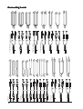
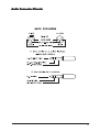
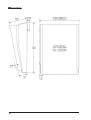
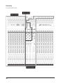
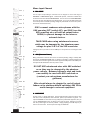
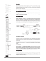
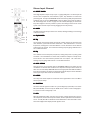
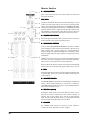
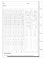
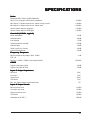
User Guide
1
IMPORTANT
Please read this manual
carefully before using
your mixer for the first time.
© Harman International Industries Ltd. 2003
All rights reserved
Parts of the design of this product may be protected by worldwide patents.
Part No. ZM0288
Issue: 1
Soundcraft is a trading division of Harman International Industries Ltd. Information in this manual
is subject to change without notice and does not represent a commitment on the part of the
vendor. Soundcraft shall not be liable for any loss or damage whatsoever arising from the use of
information or any error contained in this manual.
No part of this manual may be reproduced, stored in a retrieval system, or transmitted, in any
form or by any means, electronic, electrical, mechanical, optical, chemical, including photocopying
and recording, for any purpose without the express written permission of Soundcraft.
Harman International Industries Limited
Cranborne House
Cranborne Road
POTTERS BAR
Hertfordshire
EN6 3JN
UK
Tel:
+44 (0)1707 665000
Fax: +44 (0)1707 660742
http://www.soundcraft.com
2
Contents
INTRODUCTION
Featur
es
Features
ranty
arranty
War
5
6
7
INST
ALLA
TION
INSTALLA
ALLATION
9
WARNING
Pr
ecautions and Safety Instr
uctions
Precautions
Instructions
10
11
General Precautions
Handling and Transport
Power Supplies & Cables
Signal Levels
11
11
11
11
Mains Installation
11
General Wiring Procedures
Initial Wiring Considerations
Audio Wiring
Shielding
Points to Remember
11
12
12
12
13
Setting Up & TTrr oubleshooting
14
Initial set-up
Troubleshooting
14
14
Connecting Leads
Audio Connector Pinouts
Dimensions
16
17
18
BLOCK DIAGRAM
19
USING THE CONSOLE
21
Overview
Mono Input Channel
Stereo Input Channel
Master Section
Mark-up Sheet
22
23
27
28
30
SPECIFICA
TIONS
SPECIFICATIONS
31
3
4
INTRODUCTION
5
Featur
es
Features
The LX7-II combines the essential Soundcraft live mixer qualities with basic recording-oriented features, in a compact frame that’s
light enough for one person to carry yet easy to configure and use. This makes it especially suitable for multi-purpose use in venues
such as small halls and community centres, while its direct channel outputs make the LX7-II an ideal choice for bands who need
a live desk that can double up in the studio.
Housed in a choice of 16, 24 or 32 channel frame, LX7-II provides 24, 32 or 40 inputs - with no less than 13 separate bus outputs
including mix, 4 groups, a dedicated mono bus for centre speaker clusters, side or rear fills, and six auxiliary busses.
There are also 8, 16 or 24 direct outs, depending on the frame size of your console.
LX7-II’s balanced mic inputs all use Soundcraft new GB30 padless mic preamp providing 60dB of gain and 22dBu of headroom.
Each input also includes 4 band EQ with two swept mid frequency controls. In addition, EQ In/Out switch and steep 18dB/Octave
High Pass Filter, allow effective audio control in difficult venues whilst the six auxiliary sends are pre-post switchable in pairs from
each channel, providing a maximum of 4 pre-fader and six post-fader. This makes LX7-II equally applicable for foldback - heavy
performance or in situations where more effects are required.
LX7-II groups section houses two further stereo inputs - with EQ, auxiliaries for keyboards or stereo recording devices - as well as
two FX returns. All four groups are routable to mix and include 12 segment bargraph metering for accurate monitoring and inserts.
Six auxiliary masters on rotary controls also included AFL soloing.
In the master section there is talkback provision to all pre-fade auxiliaries and the mix. Phantom power in banks of four, and a two
track return for pre-show music are also present. A “two-track” to mix switch allows the engineer to play CD’s over the main PA
whilst back-stage set-up is going on, with one press of a button. The mix is also routable to the separate mono bus if mono PAs are
required.
LX7-II is built in a rugged wedge-shaped steel chassis with an internal power supply, professional all-metal jackfield and connectors
on the rear of the console. All inputs and outputs are balanced.
Applications incluse : Gigging Bands, Small installations, Small venues, Theatres, Houses of Worship and Live & studio recording.
6
War
ranty
arranty
1
2
3
4
5
6.
7.
Soundcraft is a trading division of Harman International Industries Ltd.
End User means the person who first puts the equipment into regular operation.
Dealer means the person other than Soundcraft (if any) from whom the End User purchased
the Equipment, provided such a person is authorised for this purpose by Soundcraft or its
accredited Distributor.
Equipment means the equipment supplied with this manual.
If within the period of twelve months from the date of delivery of the Equipment to the End
User it shall prove defective by reason only of faulty materials and/or workmanship to such
an extent that the effectiveness and/or usability thereof is materially affected the Equipment
or the defective component should be returned to the Dealer or to Soundcraft and subject to
the following conditions the Dealer or Soundcraft will repair or replace the defective
components. Any components replaced will become the property of Soundcraft.
Any Equipment or component returned will be at the risk of the End User whilst in transit
(both to and from the Dealer or Soundcraft) and postage must be prepaid.
This warranty shall only be available if:
a) the Equipment has been properly installed in accordance with instructions contained in
Soundcraft's manual; and
b) the End User has notified Soundcraft or the Dealer within 14 days of the defect appearing; and
c) no persons other than authorised representatives of Soundcraft or the Dealer have
effected any replacement of parts maintenance adjustments or repairs to the Equipment;
and
d) the End User has used the Equipment only for such purposes as Soundcraft recommends, with only such operating supplies as meet Soundcraft's specifications and otherwise
in all respects in accordance Soundcraft's recommendations.
Defects arising as a result of the following are not covered by this Warranty: faulty or
negligent handling, chemical or electro-chemical or electrical influences, accidental
damage, Acts of God, neglect, deficiency in electrical power, air-conditioning or humidity
control.
The benefit of this Warranty may not be assigned by the End User.
End Users who are consumers should note their rights under this Warranty are in addition to
and do not affect any other rights to which they may be entitled against the seller of the
Equipment.
7
8
INST
ALLA
TION
INSTALLA
ALLATION
For your own safety and to
avoid invalidation of the
warranty please read this
section carefully.
9
WARNING
THIS UNIT MUST BE EARTHED
Under no circumstances should the mains earth be disconnected from the
mains lead.
The wires in the mains lead are coloured in accordance with the following code:
Earth:
Green and Yellow (Green/Yellow - US)
Neutral:
Blue (White - US)
Live:
Brown (Black - US)
As the colours of the wires in the mains lead may not correspond with the coloured markings identifying the terminals in your plug,
proceed as follows:
The wire which is coloured Green and Yellow must be connected to the terminal in the plug which is marked with the letter
E or by the earth symbol.
The wire which is coloured Blue must be connected to the terminal in the plug which is marked with the letter N.
The wire which is coloured Brown must be connected to the terminal in the plug which is marked with the letter L.
Ensure that these colour codings are followed carefully in the event of the plug being changed.
To avoid the risk of fire, replace the mains fuse only with the correct value
fuse, as marked on the rear panel.
The internal power supply unit contains no user serviceable parts. Refer
all servicing to a qualified service engineer, through the appropriate
Soundcraft dealer.
10
Pr
ecautions and Safety Instr
uctions
Precautions
Instructions
General Precautions
Avoid storing or using the mixing console in conditions of excessive heat or cold, or in positions where it is likely to be subject to
vibration, dust or moisture. Do not use any liquids to clean the fascia of the unit: a soft dry cloth is ideal.
Avoid using the console close to strong sources of electromagnetic radiation (e.g. video monitors, high-power electric cabling): this
may cause degradation of the audio quality due to induced voltages in connecting leads and chassis.
Caution! In all cases, refer servicing to qualified personnel.
Handling and Transport
The console is supplied in a strong carton. If it is necessary to move it any distance after installation it is recommended that this
packing is used to protect it. Be sure to disconnect all cabling before moving. If the console is to be regularly moved we recommend
that it is installed in a foam lined flightcase. At all times avoid applying excessive force to any knobs, switches or connectors.
Power Cable
Always use the power supply cable supplied with the mixer: the use of alternative cables may cause damage and voids the
warranty.
W a r n i n g ! In the event of an electrical storm, or large mains voltage
fluctuations, immediately switch off the mixer and unplug from the mains.
Signal Levels
It is important to supply the correct input levels to the console, otherwise signal to noise ratio or distortion performance may be
degraded; and in extreme cases, damage to the internal) circuitry may result. Likewise, on all balanced inputs avoid sources with
large common mode DC, AC or RF voltages, as these will reduce the available signal range on the inputs. Note that OdBu =0.775V
RMS.
Refer to the Specifications section for details of input and output levels.
Mains Installation
General Wiring Procedures
To take full advantage of the excellent signal to noise ratio and low distortion of Soundcraft consoles, care must be taken to ensure
that incorrect installation and wiring does not degrade the performance of the desk. Hum, buzz, instability and Radio Frequency
interference can usually be traced to earth loops and inferior earthing systems. In some areas, especially heavily industrial areas,
the incoming mains earth will not be adequate and a separate technical earth for all the audio equipment must be supplied.
However, check with your local electricity supply company to ensure that safety regulations are not infringed or negated.
The successful, hum free, installation of a system requires forethought, and the establishment of a set of ground rules, which must
be consistently adhered to at all stages of installation.
11
Initial Wiring Considerations
For optimum performance, it is essential for the earthing system to be clean and noise free, as all signals are referenced to this
earth. A central point should be decided on for the main earth point system, and all earths should be 'star fed' from this point. It
is common electrical practice to `daisy chain' the earths to all electrical outlets but this method is unsuitable for audio installations.
The preferred method is to run an individual earth wire from each outlet, back to the system star point to provide a safety earth
screen reference for each piece of equipment.A separate earth wire should also be run from each equipment rack and area, to the
star point. This may or may not be used depending on circumstances, but it is easier to install in the first place, than later when
problems arise.The location of the star point should be a convenient, easily accessible place, preferably at the rear of the console
or in the main equipment rack.
Install separate 'clean' and 'dirty' mains outlets, wired individually back to the incoming mains distribution box. Use the 'clean'
supply for all audio equipment and the `dirty' supply for all lighting, etc. Never mix the two systems.
If necessary, to provide sufficient isolation from mains borne interference, install an isolating transformer. This should be provided
with a Faraday Shield which must be connected with earth.
Never locate the incoming mains distribution box near audio equipment, especially tape recorders, which are very sensitive to
electro-magnetic fields.
Ensure that all equipment racks are connected to earth, via a separate wire back to the star point.
Equipment which has unbalanced inputs and outputs may need to be isolated from the rack to prevent earth loops.
Audio Wiring
Having provided all equipment with power and earthing connections, consideration must be given to the method of providing audio
interconnection and adequate screening of those interconnections. This must be done in a logical sequence to avoid problems and
assist in the localisation of problem equipment.
Connect the FOH or Monitor system to the console and check for any hum, buzz, or RFI. Only when you are satisfied with the
quietness of the console and the PA system should you proceed with the next step.
Connect stereo or multitracktape recorders, FX and foldback sends one at a time, checking and isolating any connection which
degrades performance.
Connect all other peripheral devices.
Connect all microphone lines.
By following this sequence much time and future trouble will be saved, and the result will be a quiet, stable system.
Shielding
Audio equipment is supplied with a variety of input and output configurations, which must be taken into consideration when
deciding where the screen connections should be made. There are three sources of unwanted signal being impressed on the
screen, which are as follows:
Extraneous electrostatic or electromagnetic fields.
Noise and interference on the earth line.
Capacitive coupling between the screen and signal wires.
To minimise the adverse affects of the unwanted coupling to the signal wires, it is important that the screen is connected at one end
only, i.e. the screen must not carry any signal) current. Any signal) on the wires within the screen will be capacitively coupled to the
screen. This current will ultimately be returned to the source of the signal, either directly, if the screen is connected at the signal
source end, or indirectly via the earthing system, if the signal is connected at the signal destination end. The indirect connection will
cause an increase in high frequency cross-talk, and should be avoided wherever possible.
Therefore, in general, always connect the shield only at the signal source end. In high RF areas, the screen can also be connected
to earth via a 0.01 mF capacitor. This will present a short circuit at RF frequencies, thus lowering the effective shield impedance to
ground. However, at low audio frequencies the reactance of the capacitor will be sufficiently high not to cause an earth loop
problem.
12
Points to Remember
In all cases, use good quality twin screened audio cable. Check for instability at the output.
Always connect both conductors at both ends, and ensure that the screen is only connected at one end.
Do not disconnect the mains earth from each piece of equipment. This is needed to provide both safety and screen returns to the
system star point.
Equipment which has balanced inputs and outputs may need to be electrically isolated from the equipment rack and/or other
equipment, to avoid earth loops.
It is important to remember that all equipment which is connected to the mains is a potential source of hum and interference and
may radiate both electrostatic or electromagnetic radiation. In addition, the mains will also act as a carrier for many forms of RF
interference generated by electric motors, air-conditioning units, thyristor light dimmers etc. Unless the earth system is clean, all
attempts to improve hum noise levels will be futile. In extreme cases there will be no alternative but to provide a completely
separate and independent `technical earth' to replace the incoming 'noisy earth'. However, always consult your local electricity
supply authority to ensure that safety regulations are not being infringed.
13
Setting Up & T
Trr oubleshooting
Initial set-up
Once you have connected up your system (see the sections on connection and wiring earlier in this manual for guidance) you are
ready to set initial positions for the controls on your mixer.
Set up individual input channel as follows:
Connect your sources (microphone, keyboard etc.) to the required inputs and release the MUTE switches. Note: Phantom
powered mics should be connected before the 48V is switched on.
Set Master faders at 0, input faders at 0, route the channels to MIX and set power amplifier level to suit the application.
Provide a typical performance level signal and press the PFL button on the first channel, monitoring the level on the
bargraph meters.
Adjust the input gain until the meter display is in the amber section, with occasional peaks to the first red LED at a typical
maximum source level. This allows sufficient headroom to accommodate peaks and establishes the maximum level for
normal operation (but see note below).
Repeat this procedure on other channels as required.
Listen carefully for the characteristic sound of `feedback’. If you cannot achieve satisfactory input level setting without
feedback, check microphone and speaker placement and repeat the exercise. If feedback persists, it may be necessary to
use a Graphic Equaliser to reduce the system response at particular resonant frequencies.
Note: The initial settings should only be regarded as a starting point for your mix. It is important to remember that many factors
affect the sound during a live performance, for instance the channel EQ settings or even the size of the audience!
You are now ready to start building the mix and this should be done progressively, listening carefully for each component in the mix
and watching the meters for any hint of overload. If this occurs, back off the appropriate Channel Fader slightly until the level is out
of the red segments, or adjust the Mix Master Faders. This procedure will ensure that the mixer is set up correctly, with adequate
headroom. If more amplification is needed, adjust the power amplifier level controls.
Troubleshooting
No P
ower
Po
Is the mains supply present?
Is the mains lead firmly connected?
Check the mains fusing
If only one of the power indicators is illuminated, consult your Soundcraft dealer
Condenser Mic N
ot W
or
king
No
Wor
orking
Is the 48V turned on?
Is the mic plugged into the Mic input?
Is the mic cable a balanced 3-wire type?
14
Me
s no
wing an
Metter
ers
nott sho
showing
anyy signal
Has the input gain been set correctly? (see above.)
Is the source connected to the appropriate input socket for the level of signal?
Do you have something connecetd on the Inserts, and is that external device switched on?
Are the Master faders set at max., are input faders set high enough and is the channel routed to the output being monitored?
Is the MUTE switch released on the relevant channels?
Is the appropriate monitor select switch pressed?
Is there a PFL/AFL pressed on another channel?
No Mix output
Check that the Mix Master Fader is up?
Check that the 2TK REPLACES MIX switch is released?
No Monit
or output
Monitor
Is a headphone jack plugged in?
Is the Monitor + Phones control set high enough?
Is the appropriate monitor select switch pressed?
Headphones Dis
ting
Disttor
orting
Are the headphones less than 200Ω impedance?
Is the Monitor + Phones level set too high?
15
16
Insert Leads
Unbalanced
Balanced
’Y’ Leads (Unbalanced)
Headphone Splitter
’Y’ Leads (Balanced)
Connecting Leads
Audio Connector Pinouts
17
Dimensions
18
BLOCK DIAGRAM
19
20
USING THE CONSOLE
21
Overview
A 16 channel frame is shown.
22
Mono Input Channel
1 - MIC INPUT
The mic input accepts XLR-type connectors and is designed to suit a wide range of
BALANCED or UNBALANCED signals. Professional dynamic, condenser or ribbon mics
are best because these will be LOW IMPEDANCE. You can use low-cost HIGH IMPEDANCE
mics, but the level of background noise will be higher. If you press the 48V switch down
the socket provides a suitable powering voltage for professional condenser mics (this is
also known as Phantom Power).
ONLY connect condenser microphones with the
48V powering OFF (switch UP), and ONLY turn the
48V powering on or off with all output faders
DOWN, to prevent damage to the mixer or
external devices.
TAKE CARE when using unbalanced sources,
which may be damaged by the phantom power
voltage on pins 2 & 3 of the XLR connector.
Unplug any mics if you want to use the LINE Input. The input level is set using the GAIN
knob.
2 - 48V (Phant
om P
ower)
(Phantom
Po
Many professional condenser mics need an external powering voltage, normally 48V,
also known as PHANTOM POWER. This is a method of sending a powering voltage down
the same wires as the mic signal. Each switch supplies the 48V power to four MIC inputs.
The adjacent LED illuminates when the power is active.
DO NOT USE unbalanced mics with 48V switched
on as they may be damaged by the phantom
power voltage. Balanced dynamic mics and leads
can normally be used with 48V switched on
(contact your microphone manufacturer for
guidance)
Mics should always be plugged in, and all output
faders set to minimum before switching 48V ON to
avoid damage to external equipment
3 - LINE INPUT
Accepts 3-pole `A’ gauge (TRS) jacks. Use this high impedance input for sources other
than mics, such as keyboards, drum machines, synths, tape machines or guitars. The
input is BALANCED for low noise and top quality from professional equipment, but you
can use UNBALANCED sources by wiring up the jacks as shown, although you should
then keep cable lengths as short as possible. Unplug anything in the MIC input if you
want to use this socket. Set the input level using the GAIN knob.
23
4-G
AIN
GAIN
This knob sets how much of the source signal is sent to the rest of the mixer. Too high,
and the signal will distort as it overloads the channel. Too low, and the level of any
background hiss will be more noticeable and you may not be able to get enough signal
level to the output of the mixer.
See `Setting Up & Troubleshooting’ on page 20 to learn how to set GAIN correctly.
5-1
00Hz HI-P
ASS FIL
TER
100Hz
HI-PASS
FILTER
Pressing this switch activates a steep 18dB per octave filter which reduces the level of
bass frequencies only. Use this in live PA situations to clean up the mix, reducing stage
rumble or ‘popping’ from microphones.
6 - INSERT POINT
The unbalanced, pre-EQ insert point is a break in the channel signal path, allowing
limiters, compressors, special EQ or other signal processing units to be added in the
signal path. The Insert is a 3-pole ‘A’ gauge jack socket which is normally bypassed.
When a jack is inserted, the signal path is broken, just before the EQ section. The Send
may be tapped off as an alternative pre-fade, pre-EQ direct output if required, using a
lead with tip and ring shorted together so that the signal path is not interrupted.
7 - DIRE
CT OUTPUT
DIRECT
Channels 1-8/1-16/1-24 (see block diagram) have a dedicated Direct Output which
allows direct connection to external devices, for example to feed Tape Machines or
effects units.
The pre-fade direct output level may be monitored by pressing the PFL switch on the
appropriate channel to feed the pre-fade signal to the monitors and the bargraph
meters.
8 - DIR. PRE
The Direct Outputs are normally set POST-FADER for use as effects sends or to provide
fader control of recording levels in a studio recording application. For live recording the
outputs can be individually changed to PRE-FADER by pressing this switch, so that the
direct output level remains unaffected by fader settings for the main PA mix.
9 - EQU
ALISER
EQUALISER
The Equaliser (EQ) allows fine manipulation of the frequency bands, and is particularly
useful for improving the sound in live PA applications where the original signal is often
far from ideal and where slight boosting or cutting of particular voice frequencies can
really make a difference to clarity.
24
HF EQ
Turn clockwise to boost high (treble) frequencies (12kHz and above) by up to 15dB,
adding crispness to cymbals, vocals and electronic instruments. Turn anticlockwise to
cut by up to 15dB, reducing hiss or excessive sibilance which can occur with certain
types of microphone. Set the knob in the centre-detented position when not required.
MID EQ (HMID & LMID)
There are two pairs of knobs which work together to form HI and LO MID frequency EQ
sections. The lower knob in each pair provides 15dB of boost and cut, just like the HF
EQ knob, but the frequency at which this occurs can be set by the upper knob over a
range of 550Hz to 13kHz (HMID) or 80Hz to 1.9kHz (LMID). This allows some truly
creative improvement of the signal in live situations, because the mid bands cover the
range of most vocals. Listen carefully as you use these controls together to find how
particular characteristics of, for instance, a vocal signal can be enhanced or reduced.
Set the gain (lower) knob to the centre-detented position when not required. Note: Q
is set at 1.5.
LF EQ
Turn clockwise to boost low (bass) frequencies (60Hz and below) by up to 15dB,
adding warmth to vocals or extra punch to synths, guitars and drums. Turn anticlockwise
to cut low frequencies by up to 15dB for reducing hum, stage rumble or to improve a
mushy sound. Set the knob to the centre-detented position when not required.
10 - EQ S
WIT
CH
SWIT
WITCH
The EQ switch bypasses the Equalisation section when released. Alternately pressing
and releasing the switch provides an easy way of comparing the equalised and
unequalised signals.
11 - A
UX SENDS
AUX
These are used to set up separate mixes for FOLDBACK, EFFECTS or recording, and the
combination of each Aux Send is mixed to the respective Aux Output at the rear of the
mixer. For Effects it is useful for the signal to fade up and down with the fader (this is
called POST-FADE), but for Foldback or Monitor feeds it is important for the send to be
independent of the fader (this is called PRE-FADE). All Aux Sends are muted with the
other channel outputs when the MUTE switch is pressed.
All six Aux Sends are POST-EQ, unless the EQ is bypassed using the EQ switch (see
above) and are normally POST-FADE for use as effects sends or additional submixes.
Aux’s 1 & 2 and 3 & 4 may if required be switched in pairs to PRE-FADE by pressing
the respective PRE switch, for use as foldback or monitor feeds. Aux’s 5 & 6 always
remain POST-FADE.
12 - P
AN
PAN
This control sets the amount of the channel signal feeding the Left and Right MIX
buses, allowing you to move the source smoothly across the stereo image. When the
control is turned fully right or left you are able to route the signal at unity gain to either
left or right outputs individually.
13 - MUTE
All outputs from the channel except inserts are active when the MUTE switch is released
and muted when the switch is down, allowing levels to be pre-set before the signal is
required.
25
14 - F
ADER
FADER
The 100mm FADER allows precise balancing of the various source signals being mixed
to the Master Section. You get most control when the input Sensitivity is set up correctly,
giving full travel on the fader. See the `Setting Up & Troubleshooting’ section on page
20 for help in setting a suitable signal level.
15 - R
OUTING
ROUTING
The channel signal may be routed to the main stereo MIX or pairs of group busses (1-2,
3-4) by pressing the respective switches, with the channel signal fed proportionately to
left (1, 3) or right (2, 4) depending on the position of the PAN control (11). The channel
signal may also be routed to the separate centre (mono) bus by pressing the C switch,
unaffected by the position of the PAN control.
16 - PFL/PEAK
When the latching PFL switch is pressed, the pre-fade, post-EQ signal is fed to the
headphones, control room output and meters, where it replaces the selected monitor
source. The adjacent LED lights to identify the selected channel and the PFL/AFL LED on
the Master section illuminates to warn that a PFL is active. This is a useful way of
listening to any required input signal without interrupting the main mix, for making
adjustments or tracing problems.
When the PFL switch is released the LED serves as a PEAK indicator which illuminates
approximately 4dB before clipping to give warning of a possible overload. The signal is
sampled both after the HF EQ and also POST EQ.
26
Stereo Input Channel
1 - INPUT JJA
ACKS
These high impedance inputs accept 3-pole `A’ gauge (TRS) jacks. Use these inputs for
sources such as keyboards, drum machines, synths, tape machines or returns from
processing units. The inputs are BALANCED for low noise and top quality from professional
equipment, but you can use UNBALANCED sources by wiring up the jacks as shown in
the “Connecting Leads” section on page 22 in this manual, although you should then
keep cable lengths as short as possible to prevent ‘hum’ being induced into the sound
system. Mono sources may be used by plugging into the left jack only.
2-G
AIN
GAIN
The GAIN control sets the input level to the channel, allowing matching to a wide range
of line level sources.
3 - EQU
ALISER
EQUALISER
HF EQ
Turn clockwise to boost high (treble) frequencies, adding crispness to percussion from
drum machines, synths and electronic instruments. Turn anticlockwise to cut these
frequencies, reducing hiss or excessive brilliance. Set the knob in the centre-detented
position when not required. The control has a shelving response giving 15dB of boost or
cut at 12kHz and above.
LF EQ
Turn clockwise to boost low (bass) frequencies, adding extra punch to synths, guitars
and drums. Turn anticlockwise to reduce hum, boominess or improve a mushy sound.
Set the knob to the centre-detented position when not required. The control has a
shelving response giving 15dB of boost or cut at 60Hz and below.
4-A
UX SENDS
AUX
These are used to set up separate mixes for FOLDBACK, EFFECTS or recording, and the
combination of each Aux Send is mixed to the respective Aux Output at the rear of the
mixer. The sends are always PRE-FADE which is most appropriate for Foldback or Monitor
feeds, but note that the Line Inputs on pairs of Mono channels may be used as alternative
stereo inputs if post-fade sends are essential for effects.
5 - LEVEL
The rotary level control adjusts the overall level of the signal which is fed to the Mix or
selected pair of Groups.
6-R
OUTING
ROUTING
The Stereo channel signal is fed either to a pair of Subgroups (switch UP) or the stereo
Mix (switch DOWN), at a level set by the LEVEL control. Stereo 1 feeds to Subgroups 1
& 2, Stereo 2 feeds to Subgroups 3 & 4.
7 - PFL
When the latching PFL switch is pressed, the pre-fade, post-EQ signal is fed in mono to
the headphones, control room output and meters, where it replaces the selected monitor
source. The PFL/AFL LED on the Master section illuminates to warn that a PFL is active.
The Left and Right meters display the PFL signal in mono.
27
Master Section
1-A
UX MAS
TERS
AUX
MASTERS
Each of the six AUX outputs has a master output level control and
associated AFL switch.
AUX AFLs
Just as the Channel PFL switches allow pre-fade listening, so you can
monitor each AUX output after the level control by pressing the AFL
switch. This routes the AUX output signal to the MONITOR or PHONES,
replacing any existing signal which is selected. The METERS also switch
from the selected source to display the PFL/AFL signal and the PFL/
AFL LED lights to warn that a PFL or AFL switch is pressed. When you
release the switch the Monitor swaps back to the previous source.
2 - PO
WER INDIC
ATORS
POWER
INDICA
These LEDs light to show that power is connected to the console and
that the internal power supply is operating correctly.
3 - BAR
GRAPH METERS
BARGRAPH
3-colour peak reading BARGRAPH METERS are provided to monitor
the four Subgroup outputs and the selected Monitor + Phones source
(2TK, C (mono), Mix or Groups), giving you a constant warning of
excessive peaks in the signal which might cause overloading. Aim to
keep the signal within the amber segments at peak levels for best
performance.
Similarly, if the output level is too low and hardly registering at all on
the meters, the level of background noise may become significant.
Take care to set up the input levels for best performance.
When any PFL or AFL switch is pressed, the L & R meters automatically
switch to show the selected PFL/AFL signal on both meters, in mono.
4 - MIX
Pressing the Mix switch routes the post-fade Subgroup signals in pairs
to the main Mix. Groups 1 & 3 are routed to Mix L, Groups 2 & 4 are
routed to Mix R.
5 - MAS
TER F
ADERS
MASTER
FADERS
The MASTER FADERS set the final level of the Subgroup and Mix L & R
outputs. These should normally be set close to the `0’ mark if the
input GAIN settings have been correctly set, to give maximum travel on
the faders for smoothest control.
6 - MIX TTO
O C (mono)
Pressing this switch routes the post-fade Mix L/R outputs to the C
(mono) bus to create a separate mono mix to feed, for example, an
induction loop or centre cluster. Note: If there are input channels
which are routed both to Mix and C (mono), pressing this switch will
have an additive effect which may lead to feedback.
7 - PHONES
The PHONES output appears on a 3-pole 1/4” jack, suitable for
headphones with an impedance of 200Ω or higher.
28
8 - TB LEVEL
A balanced input is provided for a Talkback microphone. The signal may be routed
selectively to Aux 1/2 or 3/4 (which might typically be used for performers’ foldback) or
Mix L/R by pressing the appropriate switches. The signal level is adjusted by the TB LEVEL
control.
9-S
TERE
O RETURNS
STERE
TEREO
Two balanced Stereo Returns are available for the outputs of effects units and are mixed
directly to the Mix L/R busses at a level set by the RET-1 or RET-2 controls. If a mono
source is used, plugging into the Left jack only automatically feeds to the signal to both
Left and Right.
10 - 2TK LEVEL
The rotary control sets the level of the 2 Track Tape input, which is routed to the headphones,
monitor outputs and meters, or directly to the Mix outputs by pressing the adjacent switch
(12). These unbalanced inputs, on RCA phono connectors, are ideal to connect the
playback of a tape machine for monitoring.
11 - 2TK REPLA
CES MIX OUTPUT!
REPLACES
This switch does what it says! When pressed the Mix output is switched to the 2 Track
input and is an ideal way of feeding pre-show music to the main outputs in live applications
without using up valuable input channels. For example, with the switch pressed and a CD
connected and playing pre-show music, the engineer can be setting up channel levels,
adjusting EQ, talking back to performers and monitoring any part of the mix (including
final Mix) without affecting the sound to the audience. Releasing the switch instantly
swaps the Mix Outputs back to the mixer and cuts off the CD.
CAUTION: Pressing this switch cuts off the
normal Mix L/R signal and it should therefore NOT
be used during live performance or recording
12 - MONIT
OR SOUR
CE SELE
CT
MONITOR
SOURCE
SELECT
These switches allow a choice of 2TK, C (mono), Mix or Groups as the source for the
Phones, Monitor outputs and meters, and may be selected individually or as a combination.
NOTE: If NO switches are pressed, there will be NO signal on the meters or monitors!
13 - MONIT
OR + PHONES
MONITOR
This control sets the output level to the MONITOR LEFT & RIGHT outputs. If Headphones
are plugged into the PHONES jack the Monitor outputs are cut off, and the knob then sets
the headphone listening level. When the PHONES are unplugged the Monitor output is
restored. The source for the Monitor and Phones is selected by the five switches (13)
above the control.
When any PFL or AFL switch is pressed the source for the Monitor outputs and Headphones
is switched to the mono PFL/AFL signal without interrupting the other outputs from the
mixer, to allow individual signals to be monitored. The original monitor source is restored
when the PFL/AFL switches are released.
14 - PFL/AFL
The PFL/AFL LED illuminates to show that a PFL/AFL is active and is the source for the
monitors and meters. The LED will normally be OFF
29
Mark-up Sheet
You may freely copy this page to mark control positions to assist in resetting the desk between performances.
30
SPECIFICA
TIONS
SPECIFICATIONS
Noise
Measured RMS, 22Hz to 22kHz Bandwidth
Mic E.I.N. @ unity gain,150W source impedance
Mix Output, 24 inputs routed to mix, faders at unity, muted
Mix Output, 24 inputs routed to mix, faders down
Input to Direct output at unity gain
Input to Direct output at 40dB gain
Cr
osstalk (@1kHz, typical)
Crosstalk
Fader attenuation
Aux attenuation
Pan isolation
Adjacent channel crosstalk
Channel Mute
Fader cut-off (rel. 0 mark)
Aux Send pots offness
Fr
equency Response
Frequency
Mic/Line Input to any output, 20Hz - 20kHz
THD + N
Mic sens. -30dBu, +20dBu at all outputs @1kHz
CMRR
Typical @ max gain @ 1kHz
Typical @ any gain @ 50Hz
Input & Output Impedance
Mic Input
Line Input
Stereo Input
2TK Return
Mix, Aux, Direct Outputs, and Insert Sends
Input & Output Levels
Mic Input max. level
Line Input max. level
Stereo Input max. level
2TK Return
Headphones (@ 200Ω)
-129dBu
<-80dBu
<-100dBu
<-90dBu
<-80dBu
>95dB
>80dB
>75dB
>-80dB
>90dB
>90dB
>80dB
<1dB
<0.006%
>80dB
>60dB
1.8kΩ
10kΩ
8.6kΩ
12kΩ
75Ω
+22dBu
+22dBu
+22dBu
>30dBu
150mW
31
32