1
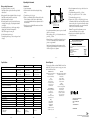
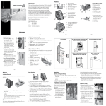
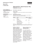
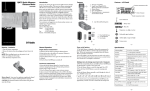
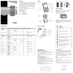
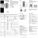
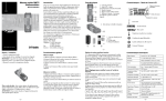
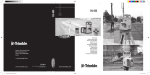
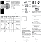
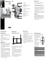
AL 24/28/32 - A/M Series
Features
Maintenance and Care
Auto Levels
User Guide
•
1
13
2
12
3
4
5
11
10
6
9
7
01. Focusing knob
02. Sighting guide
03. Crosshairs’ adjustment screws (under cover)
04. Crosshairs’ focusing ring
05. Eyepiece
06. Horizontal rotation ring and angle index
07. Leveling screws
08. Base plate
09. Circular level adjustment screws
10. Horizontal tangent knob
11. Circular level
12. Mirror for reading circular level
13. Objective
8
• As with all precision instruments, the auto level should be
transported and stored in its carrying case.
• When carrying the instrument mounted to a tripod, be sure
to carry it vertically rather than over your shoulder.
• Whenever possible, store the instrument in a dry, shady area.
• Wipe the instrument clean with a cloth. Clean the objective
and eyepieces with special care using a damp tissue or soft,
clean, lint-free cotton cloth.
• When working in wet weather, wipe off the instrument and
carrying case in the field and let them dry completely indoors
with the case open.
Safety Information
Included in this manual are Cautions and Notes. Each of
these words represents a level of danger or concern. A Caution
indicates a hazard or unsafe practice that could result in
minor injury or property damage. A Note indicates important
information unrelated to safety.
www.trimble.com
–2–
How to Use the Instrument
Taking Measurements
Setting Up the Instrument
1.Set up the tripod at a height appropriate for your use.
Note: Make sure the tripod is stable and the tripod head is
relatively level.
2.Attach the instrument to the tripod.
3.Level the instrument using the circular level as a reference.
4.Focus the telescope crosshairs by turning the crosshairs’
focusing ring.
Determining the Difference in Elevation
1.259
B
0.467
–5–
b1
a1
1.726
Aligning the Instrument
1.Align the telescope to the grade rod using the sighting guides.
2.Turn the focusing knob to bring the grade rod into sharp
focus. Precisely sight the center of the grade rod in the
telescope crosshairs using the horizontal tangent knob.
3.Check for parallax shift.
Note: No parallax exists if the crosshairs and the grade rod
graduations remain in coincidence even when you change
your viewing angle (move your eye up/down and left/right in
front of the eyepiece).
Note: After the bubble in the circular level has been centered,
the compensator corrects residual line-of-sight inclinations.
The compensator does not, however, eliminate any tilts
resulting from inadequate adjustment of the circular level or
line of sight. These must be checked regularly (see Adjusting
the Instrument for more information).
–3–
A
Establishing an Elevation
1.Set up and level the instrument.
2.Set the grade rod on a known elevation (30.55 m) and take a
grade rod reading (1.72 m).
3.Add the grade rod reading to the known elevation to get the
height of instrument or HI (1.72 + 30.55 = 32.27 m).
4.Subtract the elevation of the point you want to establish
(31.02 m) from the HI (32.27) to calculate the difference
between the two points (32.27 – 31.02 =1.25 m).
5.Go to the point you want to establish and adjust the height of
the grade rod until the calculated difference (1.25) is centered
in the crosshairs.
1.Set up the instrument half way between two points (A and B).
2.Take a reading at point A (a1 = 1.726 m) and another one at
point B (b1 =1.259 m).
Note: A slight deviation of the line of sight from horizontal
will not cause any measuring error as long as the instrument
is set up approximately half way between the two points.
3.Subtract b1 from a1 to get the difference between the points
(d = 0.467 m).
Note: Point B is 0.467 higher than point A because the
difference is a positive number. If point B were lower than
point A, the number would be negative.
–6–
–4–
Taking a Distance Measurement
Note: The instrument’s stadia lines allow you to determine the
distance between the instrument and the grade rod.
1.Take readings at the upper stadia
15
line (1.436 m) and the lower stadia
14
line (1.152 m).
2.Calculate the difference between
13
the two readings (1.436 – 1.152 =
12
0.284 m).
11
3.Multiply the difference by 100
to get the distance between the
10
instrument and the grade rod
(.284 x 100 = 28.4).
Computation Example
Elevation
Center Line Reading
Distance Measurement
Upper Stadia Line Reading
Lower Stadia Line Reading
Difference
Distance (0.284 x 100)
–7–
1.294 m
1.436 m
1.152 m
0.284 m
28. 4 m
–8–
Adjusting the Instrument
Taking an Angle Measurement
1.Set up the tripod so that it is over a hub.
Note: Make sure the tripod is stable and the tripod head is
relatively level.
2.Hang a plumb-bob from the plumb-bob hook on the tripod.
Note: Make sure the plumb-bob is over the hub.
3.Attach the instrument to the tripod.
4.Center the plumb-bob over the pin in the hub by varying
the length of the tripod legs or by shifting the instrument
on the tripod.
5.Accurately align the telescope to the first target using the
sighting guides and a horizontal tangent knob.
Note: The first target is a known point.
6.Set the horizontal rotation ring to 0.
7.Accurately align the telescope to the second target and read
the angle.
Circular Level
1.Set up the instrument.
2.Center the bubble of the circular level using the leveling
screws.
3.Turn the telescope 180° (200 gon).
4 Check to see whether the bubble is still centered in the circle.
If it isn’t, eliminate one half of the error with the leveling
screws and the other half with the two adjustment screws for
the circular level.
5.Repeat the process until the bubble remains centered when
the instrument is turned.
Line of Sight
a2
b2
a1
b1
B
A
a2 = 2.423
+b1 = 0.936
d = +1.487
b2 = 1.462
-d = 1.487
c = 2.949
1.Set up the instrument half way between two points (A and B)
that are 30 to 40 m apart.
2.Take a reading at point A (a1 = 2.423 m) and another one at
point B (b1 = 0.936 m).
3.Subtract b1 from a1 to get the difference between the points
(d = +1.487 m). Make sure you note whether value d is a
positive or negative number.
Note: Because the distance from the instrument to each of
the points is equal, the difference in elevation is correct even
if the line of sight is out of adjustment.
–9–
– 10 –
Specifications
4.Move the instrument and reset it up so that it is about 2 m
behind point B.
5.Take another reading at point B (b2 = 1.462 m).
6.Add b2 to d to get value c (1.462 + 1.487 = 2.949 m).
7.Take another reading at point A (a2).
8.Compare value c (2.949) to a2. If the line of sight is correct,
both numbers should be the same. If they differ by more than
4 mm, reset the grade rod on point A and turn the crosshairs
adjustment screws (unscrew the cover to expose them) until
value c (2.949) is centered in the crosshairs.
Caution: The upper and lower adjustment screws are
counter-screws and must not be set too tightly.
9.Repeat the process until the line of sight is correct
(c and a2 are the same).
Notice to Our European Union Customers
For product recycling instructions and more information,
please go to: www.trimble.com/environment/summary.html
Recycling in Europe
To recycle Trimble WEEE, call: +31 497 53 2430, and ask for the ÒWEEE
associate,Ó or
mail a request for recycling instructions to:
Trimble Europe BV
c/o Menlo Worldwide Logistics
Meerheide 45
5521 DZ Eersel, NL
– 11 –
– 12 –
Service Request
Dimensions (L x W x H)
Instrument
Case
Weight
Instrument
Case
Accuracy
Standard deviation according to DIN 18723 on 1 km of double leveling
Leveling accuracy
Telescope
Magnification
Aperture
Telescope image
Field of view angle
Shortest focusing distance
Stadia constant
Addition constant
Automatic Compensator
Type
AL2XA, AL32A
AL2XM (-G)
– 13 –
AL24A / AL24M
AL28A / AL28M / AL28M-G
AL32A
130 x 190 x 135 mm
(5.1 x 7.5 x 5.3 in.)
170 x 280 x 190 mm
(6.7 x 11.0 x 7.5 in.)
130 x 190 x 135 mm
(5.1 x 7.5 x 5.3 in.)
170 x 280 x 190 mm
(6.7 x 11.0 x 7.5 in.)
130 x 190 x 135 mm
(5.1 x 7.5 x 5.3 in.)
170 x 280 x 190 mm
(6.7 x 11.0 x 7.5 in.)
1.6 kg (3.5 lb)
1.25 kg (2.75 lb)
1.6 kg (3.5 lb)
1.25 kg (2.75 lb)
1.6 kg (3.5 lb)
1.25 kg (2.75 lb)
+/–2.0 mm
+/–1.5 mm
+/–1.0 mm
3 mm @ 46 m
(1/8 in. @ 150 ft)
1.5 mm @ 60 m
(1/16 in. @ 200 ft)
1.5 mm @ 75
(1/16 in. @ 250 ft m)
24x
30 mm (1.2 in.)
Erect
1° 20'
0.60 m (1.97 ft)
100
0
28x
30 mm (1.2 in.)
Erect
1° 20'
0.60 m (1.97 ft)
100
0
32X
36 mm (1.4 in.)
Erect
1° 20'
0.60 m (1.97 ft)
100
0
Wire suspension: Air damped
Magnetic damped
Wire suspension: Air damped
Magnetic damped
Wire suspension:
Air damped
To locate your local dealer or authorized Trimble Service Center
outside the U.S.A for service, accessories, or spare parts, contact
one of our offices listed below.
North-Latin America
Trimble Construction Tools Division
8261 State Route 235
Dayton, Ohio 45424-6383
U.S.A.
(800) 538-7800
(Toll Free in U.S.A.)
+1-937-245-5600 Phone
+1-937-233-9004 Fax
www.trimble.com
Asia-Pacific
Trimble Navigation Singapore PTE Ltd.
80 Marine Parade Road, #22-06
Parkway Parade
Singapore, 449269
+65 6348 2212 Phone
+65 6348 2232 Fax
Africa & Middle East
Trimble Export Middle-East
P.O. Box 17760
JAFZ View, Dubai
UAE
+971-4-881-3005 Phone
+971-4-881-3007 Fax
China
Trimble Beijing
Room 2805-07, Tengda Plaza,
No. 168 Xiwai Street
Haidian District
Beijing, China 100044
+86 10 8857 7575 Phone
+86 10 8857 7161 Fax
www.trimble.com.cn
Trimble Construction Tools Division
8261 State Route 235
Dayton, Ohio 45424-6383
U.S.A.
+1-937-245-5600 Phone
Europe
Trimble GmbH
Am Prime Parc 11
65479 Raunheim
GERMANY
+49-6142-2100-0 Phone
+49-6142-2100-550 Fax
www.trimble.com
N324
– 14 –
– 15 –
© 2010, Trimble Navigation Limited. All rights reserved.
Reorder PN 1211-0151B (05/10)