1
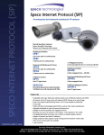
Mirror Finish Color Dome Camera CVCM6DC
Specifications
Image Sensor
Number of Pixels
Scanning System
Horizontal Resolution
Minimum Illumination
Lens
Signal to Noise Ratio
Gain Control
BLC
Synchronization
Electronic Shutter
Gamma Correction
White Balance
Video Output
Dimensions
Voltage Requirement
Current Draw
Temperature
Relative Humidity
1/3” Sony Super HAD CCD
510 H x 492 V
NTSC 2:1 interlace
420 TV lines
0.2 lux
3.6mm
>50dB
Auto
Auto
Internal
1/60 – 1/100,000 sec.
.45
Auto (2500° - 9500° K)
1V P-P (into 75Ω)
4-3/8” diameter x 3-5/8” high
12 +/- 10% VDC regulated
100 mA DC
-14°F - +122°F operating
-22° F - +158°F storage
0-95%
Mirror Finish Color Dome Camera
Wall or Ceiling Mount
CVCM6DC
Installation Instructions
Always use discretion when installing video and/or audio surveillance equipment
especially when there is an expectation of privacy. Inquire regarding federal, state
and/or local regulations applicable to the lawful installation of video and/or audio
recording or surveillance equipment. Party consent may be required.
This device complies with Part 15 of the FCC Rules.
Operation is subject to the following two conditions:
(1) This device may not cause harmful interference, and
(2) This device must accept any interference received, including interference
that may cause undesired operation.
Design and specifications are subject to change without notice.
Box Contents
(1) CVCM6DC color camera (1) EZ mount base plate
(1) Dome liner (3) Mounting screws with plastic anchors
(1) Power supply pigtail (1) Installation guide
200 New Highway
Amityville, NY 11701
1-800-645-5516
www.specotech.com
Mirror Finish Color Dome Camera CVCM6DC Installation Instructions
1
3
Preparation
Connections
4
Camera Adjustment
Note - Observe Polarity
Remove Dome Cover
1. Gently pull the inner liner away from the dome cover.
2. Carefully turn the dome cover counterclockwise
to unlock and pull it free from the housing, then set
both aside.
2
This is a 12V DC camera – to
avoid damage please observe
polarity.
2
Camera Mounting
(Wall or Ceiling Mount)
1. Remove EZ Mount Plate from
bottom of camera by turning
counterclockwise.
2. Determine if the connection wires
will exit from the bottom or side of
the base.
3. If wires are going through the side,
carefully remove the wire clearance
tab on the side of the base.
4. Mark holes for mount position as
required.
5. Attach plate to the mounting
surface using anchors and screws
supplied.
6. Feed the connectors into the wire
hole and align holes in camera base
with EZ mount plate studs.
7. Slip base over studs, gently press
base against the mounting surface
and rotate until the base locks in
place.
8. If not using EZ Mount Plate, slip
base over screws, press base
against the mounting surface and
rotate until the base locks in place.
Tighten screws until base is firmly
held but do not over tighten.
05.30.08
Use these adjustments to align the
camera position to obtain the image
desired.
Connect Wiring
Note: Depending on the
material of your mounting
surface, you may require
different screws and anchors
than those supplied.
1. Attach BNC connector from camera
to a BNC(male) connector on your
video cable.
2. IF using a plug-in power supply with
attached connector, verify that the
center pin is the plus (+) wire and
the outer shell is the negative
(-) wire.
3. IF extending power wire from a
remote power supply, verify polarity on
feed from power supply. Connect
positive (+) wire to red wire from pigtail
supplied and attach negative (-) wire to
black wire from pigtail. Verify that the
center pin of pigtail connector is
positive (+) before connecting to
the camera.
4. Connect to power supply.
5
Replace Dome Cover
1. Use a soft, lint free cloth to wipe the
dome cover and remove finger prints.
2. The dome cover may be replaced with
or without the liner.
3. If lighting is coming from behind the
camera, use the dome liner to hide the
camera position.
4. Before inserting the liner note the
position of the camera lens so the lens
will be placed at the opening of the liner
when the dome is locked in.
5. Align the dome cover tabs with the
slots in the base, gently press the cover
into the slots and rotate clockwise until it
is secure and the dome liner opening is
aligned with the camera lens.