1
Wide Dynamic Range
Dome Camera
WDR-D3
200 New Highway
Amityville, NY 11701
631-957-8700
www.specotech.com
Please read this manual thoroughly before operation and keep
it handy for further reference.
WARNING & CAUTION
CAUTION
RISK OF ELECTRIC SHOCK
DO NOT OPEN
CAUTION
:
TO REDUCE THE RISK OF ELECTRIC SHOCK
DO NOT REMOVE COVER (OR BACK).
NO US E R S E R V I C E A B L E P A RT S I N SIDE
REFER SERVICINGTO QUALIFIED
SER V ICE PERSONNEL._______________
The lighting flash with an arrowhead symbol, within an equilateral triangle is
Intended to alert the user to the presence of un-insulated “dangerous voltage”
within the product’s enclosure that may be of sufficient magnitude to constitute
a risk of electric shock to persons____________________________________
The exclamation point within an equilateral triangle is intended to alert the user
to the presence of important operating and maintenance (serving) instructions
i n t h e l it e r a t u r e a c c o m p a n y i n g t h e a p p l i a n c e _ _ _ _ _ _ _ _ _ _ _ _ _ _ _ ___
I N F O R M AT I O N - T h i s e q u i p m e n t h a s b e e n t e s t e d a n d f o u n d t o c o m p a n y w i t h
l i m i t s f o r a c l a s s a d ig i t a l device Pursuant to part 15 of the FCC rules.
Th ese lim its a re d e sign e d to provide reasonable protection against harmful
I n terference W hen the equipments operated in a commercial environment.
T h i s e q u ip m e n t g e n e ra t e s , u s e s , a n d C a n R a d i a t e r a d i o f re q u e n c y e n e r g y a n d
if n o t i n s t a l l e d a n d u s e d i n a c c o r d a n c e w it h the instruction manual, may Cause
H a rm f u l in t e rf e r e n c e t o r a d i o c o m m u n i c a t io n s . O p e r a t i o n o f this equipment in a
residential area is likely to cause harmful interference in which
C a s e t h e u s e r wi l l b e r e q u i r e d t o co r re ct t h e i n t e rf e re n ce a t h i s o wn expense.
WARNING – Change or modification not expressly approved by the manufacturer could void
the user’s authority to operate the equipment__________________________________
CAUTION : To prevent electric shock and risk of fire hazards.
DO NOT use power sources other than that specified.______
DO NOT expose this appliance to rain or moisture.000
This installation should be made by a qualified service person and should conform to all local codes.
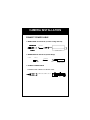
CAMERA INSTALLATION
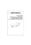
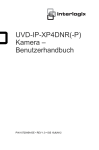
CONNECT POWER CABLE
1. WHEN USING 12 VOLTS DC (constant voltage 600 mA)
POWER INPUT:RED
CONNECT
CENTER:(+)
POWER SUPPLY
2. WHEN USING 24 VOLTS AC (40 Volt Amps)
POWER
RED(+)
CONNECT
BLACK:(-)
3. CONNECT VIDEO CABLE
-CONNECT BNC CABLE TO THE BNC JACK.
YELLOW:VIDEO OUT
POWER SUPPLY
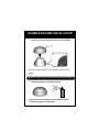
CHAMELEON DOME INSTALLATION
3. If desired, place the Chameleon Dome over the WDR-D3
Push the Chameleon Dome over the WDR-D3 until it snaps into
position.
● Notes : If painting is desired, please do so before installation
* Painting method on Chameleon Dome
* Spray the Chameleon Dome with your desired color
* If necessary apply a second coat
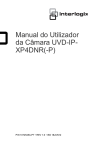
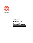
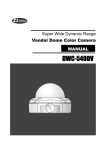
INTERNAL COMPONENTS
1. Mechanical
(2) JOY STICK
(1) DC Auto iris
2.8~10mm Lens
(1) DC AUTO-IRIS LENS
Adjust between TÅÆW (TELE ÅÆ WIDE) to set the
angle (focal length) Set the focus by adjusting 쏒N
NOTE: BOTH OF THE ABOVE ADJUSTMENTS GET LOCKED
INTO POSITION THROUGH THE USE OF "LOCKING HANDLES".
(2) JOY STICK
TO SET THE OSD (ON SCREEN DISPLAY) , PRESS THE JOY
STICK FOR ONE SECOND AND SET AS DESCRIBED
IN THE MANUAL
2. Joy Stick
UP
RIGHT
LEFT
DOWN
Push the Joy stick for one second, and the OSD appears
on the screen. Move the Joy Stick up, down, left & right to
control the OSD functions.
1. GENERAL INFORMATION
SAFETY PRECAUTION
■ Do not open and modify
Do not open the cabinet except during maintenance and installation, as it may be dangerous and cause damage.
■ Do not put objects inside the unit
Make sure that no metal objects or flammable substances get inside the camera. It could cause fire, short-circuits or
damages.
■ Be careful when handling the unit
To prevent damage, do not drop the camera or subject it to strong shock or vibration
■ Install away from electric or magnetic fields
■ Protect from humidity and dust
■ Protect from high temperature
Be careful when installing close to the ceiling, in a kitchen or boiler room, as the temperature may raise to high levels.
■ Cleaning
Dirt can be removed from the cabinet only by wiping it with a soft cloth moistened with a soft detergent solution.
■ Mounting Surface
The mounting surface material must be strong enough to secure the camera.
2. EXHIBIT
TIP FOR LOCATION OF THE CAMERA
Before sending the camera out for repair, check the items below. If the problem persists after checking these
items, contact your service center.
■ If no image appears
Is the coaxial cable attached securely?
Are the power and voltage normal?
Has the iris of the lens inside the camera been adjusted correctly (with the level volume) ?
Is there adequate illumination?
■ If the image is unclear
Is the lens in focus?
Is the lens dirty?
Dirt of fingerprints on the lens can adversely affect the images. Gently wipe any dirt or fingerprints off the lens
with a soft cloth or lens cleaning paper and cleaning fluid (commercially available).
Is the monitor adjusted correctly?
WARNING:
TO PREVENT THE RISK OF FIRE OR ELECTRIC SHOCK, DO NOT EXPOSE THIS APPLIANCE TO
RAIN OR MOISTURE.
3. CAMERA FEATURES
PRODUCT FEATURE
1. High Resolution
It has 540 lines of horizontal resolution and 460 lines of vertical resolution. (540 HTVL equivalent)
2. Superior Wide Dynamic Image Quality
It has very Wide Dynamic Range by using Pixim ORCA Chip Set.
Film-like colors are described under various Light conditions even in high dynamic range scenes
Dynamic Range is greater then 120 dB.
3. Digital Pixel System
Each pixel is processed independently to get clear and usable images.
4. Various Lens Choices
it offers flexibility of the lens from board mount to C/CS mount lens with manual and
DC auto-iris control.
5. Power Source
DUAL VOLTAGE (12VDC or 24VAC)
6. OSD control
Every function is controlled by OSD menu
- Automatic white balance
- Automatic gain control (max 60dB)
- Slow shutter, AGC on/off
- Line lock phase control
- Lens type control
- Auto exposure control
7. Synchronization
Both Internal Synchronization and External Synchronization is provided.
8. Camera ID
The title that indicated on Monitor can be appointed.
9. NTSC/PAL Selectable
NTSC or PAL is selectable by simple switch is one camera
4. CAMERA SPECIFICATION
Signal System
NTSC / PAL
Pick-up Device
1/3 inch CMOS (dramatically Dynamic range sensor)
Total of pixels
742(H) x 552(V)
Horizontal Resolution
520 Horizontal TV Lines (color)
Scanning System
525 Iines interlaced / 625 Iines interlaced
Synchronization
Internal / External
Video Output
1.0Vp-p/75 ohm Composite
Iris Control
DC Lens, Video Lens, Manual Lens
Sensitivity
0.08Lux (DSS on) with F1.2 Lens
S/N Ratio
48dB or more
Dynamic range
120dB(max), 95dB(typical)
Shutter Speed
1/60 - 1/100,000 / 1/50 - 1/100,000
Lens Mount
C/CS mount
AGC Control
0 - 60dB
OSD Menu Control
4-directional Swith with a center Push TACT Switch
Supplied Voltage
DC 12V (8V - 18V), AC 24V {(20V - 30V)option}
Power Consumption
Max 2.7W
Operating Temperature
-10°C ~ 50°C
Storage Temperature
-20°C ~ 70°C
Operating Humidity
Under 90% Non-condensing
Storage Humidity
under 95% Non-condensing
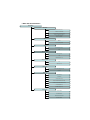
5. MENU AND SETTING DETAILS
MAIN MENU
SET UP ID
DISPLAY ID:ON or OFF
CAMERA ID : 8 CHARACTER
ID POSITION : UP-LEFT or UP-CENTER or UP-RIGHT
DOWN-LEFT or DOWN-CENTER or DOWN-RIGHT
RES : CCD-HIGH or CCD-NORMAL
PIXIM-HIGH or PIXIM-NORMAL
LENS
MANUAL
DC : LEVEL (Range 0~255)
WDR
MANUAL(Range -20 to 20)
AUTO
WB CONTROL
ATW(Range 2K~11K)
AWB
MANUAL(Range 2K ~11K)
AGC CONTROL
OFF
ON(Range 0 ~ 60)
LOW LIGHT
SLOW SHUTTER(Range OFF~X32)
AUTO D/N
SPECIAL
VIDEO(NTSC/PAL)
FLIP(ON/OFF)
SYNC(INT/INT2/L,LOCK)
BACK LIGHT(ON/OFF/BACK LIGHT JONE)
FLICKER LESS(OFF/ON/FLICKER LESS JONE)
COLER MODE(B/W,OFF)
SHARPNESS(Range -8 ~ 8)
EXIT MENU
EXIT NO CHANGE
SAVE NEW AND EXIT
RESTORE FACTORY SETTING
RELEASE VERSION
OSD MENU CONTROL
CENTER KEY - Used to access the menu mode, Also used to confirm the setting
UP / DOWN KEY - Used to choose the desired menu selection.
LEFT / RIGHT KEY - Used to choose the desired menu feature adjustment.
OSD MENU ENTER / EXIT
A. OSD MENU ENTER
• Push Center Key for 2 seconds
B. OSD MENU EXIT
• Press EXIT Menu from Main Menu
• If Pressing Set Key for 2 seconds from Main Menu appears.
In this case, just press Set Key.
C. 'SAVE' and 'QUIT‘
• Left or Right Key - Selecting Menu
• Up or Down Key - Returning to Menu
1. Press the SET key to access the main setup mode.
2. Select the desired feature using the UP or Down key.
3. Change the status of the selected feature using the LEFT or RIGHT key.
MAIN MENU
A. SETUP ID
• DISPLAY ID
- ON :The ID name will displayed in the monitor.
- OFF : The name will not displayed in the monitor.
• CAMERA ID : You can be written to 8 characteristic.
• ID POSITION : Select on screen position of the camera ID.
• RES : Select Resolution of CCD or PIXIM
B. LENS
• MANUAL : Use When using Manual lens.
• DC : You can control the brightness of the screen and adjust the desired DC level from 0 to 255.
C. WDR
•WDR (Wide Dynamic Range) : You can adjust the desired WDR level from -20 to 20.
D.FILKER LESS
•AUTO DECTECTION or SELECT AREA
E. WB CONTROL
• ATW (Auto Tracking White Balance) : The camera automatically control the white balance in any environment.
• AWB (Auto White Balance) : The white balance is automatically adjusted in a specific environment.
• MANUAL : Users can adjust the colors by adding or reducing the WB level.
You can adjust the desired WB level from 2K to 11K
F. AGC
• ON : Activate automatic gain control feature.
You can adjust the desired AGC level from 0 to 60dB.
• OFF : Deactivate automatic gain control feature.
G. LOW LIGHT
• SLOW SHUTTER : Control Image brightness by adjusting shutter speed
- AGC : Auto Gain Control setting( Range 28 to 48)
• AUTO D/N : AUTO DAY/NIGHT
H. SYNC
• INTERNAL : Internal synchronization
• INTERNAL2 : Internal synchronization (Color Rolling Mode)
• LINE LOCK : Phase adjustment may be necessary in multiple camera installations to prevent picture roll
when switching between cameras
I. EXIT MENU
• EXIT NO CHANGES : No change
• SAVE NEW AND EXIT : Save change
• RESTORE FACTORY SETTINGS : Factory default
• SW REV
J. VIDEO
• NTSC or PAL SELECTION
K. FLIP
• HORIZONTAL REVERSE
L. BACK LIGHT
• BACK LIGHT NONES ADJUST or SELECT AREA
M. COLOR MODE
• COLOR or B/W SELECTION
N. SHARPNESS
• You can adjust the desired Sharpness level from -8 to 8.
O. PREVIOUS PAGE
• PREVIOUS PAGE : Return page
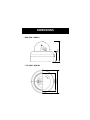
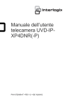
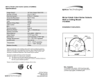
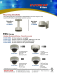
DIMENSIONS
80.00
150.00
* SIDE VIEW : WDR-D3
180.00
120.00
* TOP VIEW : WDR-D3
WARRANTY
200 New Highway
Amityville, NY 11701
631-957-8700
www.specotech.com