1
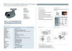
INSTRUCTION
MANUAL
Intense Light
Color Dome Camera
VL647iLT
Speco Technologies is constantly developing product improvements.
We reserve the right to modify product design and specifications without notice and without incurring any obligation.
Rev. 6/9/10
CAUTION
CAUTION
CAUTION
RISK OF ELECTRIC SHOCK
DO NOT OPEN
RISK OF ELECTRIC SHOCK
RISK OF
DOELECTRIC
NOT OPENSHOCKCAUTION:TO REDUCE THE RISK OF ELECTRIC SHOCK
DO NOT OPEN
DO NOT REMOVE COVER(OR BACK).
CAUTION:TO REDUCE THE RISK OF ELECTRIC SHOCK
USER-SERVICEABLE PARTS INSIDE.
CAUTION:TO REDUCE THE RISK OF ELECTRIC NO
SHOCK
DO NOT REMOVE COVER(OR BACK).
DO NOT REMOVE COVER(ORREFER
BACK).SERVICING TO QUALIFIED SERVICE PERSONNEL.
NO USER-SERVICEABLE PARTS INSIDE.
NO USER-SERVICEABLE PARTS INSIDE.
REFER SERVICING TO QUALIFIED SERVICE PERSONNEL.
REFER SERVICING TO QUALIFIED SERVICE PERSONNEL.
ISO14001
ISO14001
ISO14001
The lightning flash with an arrowhead symbol, within an equilateral
triangle is intended to alert the user to the presence of uninsulated
dangerous voltage within the product's enclosure that may be of
sufficient magnitude to constitute a risk of electric shock to persons.
The exclamation point within an equilateral triangle is intended to alert
the user to the presence of important operating and maintenance
(servicing) instructions in the literature accompanying the appliance.
INFORMATION - This equipment has been tested and found to comply with
limits for a Class A digital device, pursuant to part 15 of the FCC Rules & CE Rules.
These limits are designed to provide reasonable protection against harmful
interference when the equipment is operated in a commercial environment.
This equipment generates, uses, and can radiate radio frequency energy and, if
not installed and used in accordance with the instruction manual, may cause
harmful interference to radio communications.
Operation of this equipment in a residential area is likely to cause harmful
interference in which case the user will be required to correct the interference at
his own expense.
WARNING - Changes or modifications not expressly approved by the
manufacturer could void the user’s authority to operate the equipment.
CAUTION : To prevent electric shock and risk of fire hazards:
☞Do NOT use power sources other than those specified.
☞Do NOT expose this appliance to rain or moisture.
This installation should be made by a qualified service person and
should conform to all local codes.
-2-
Contents
Contents
3
Precautions
4
Sefety Instructions
5
SPECIFICATIONS
6
FEATURES
7
FEATURES
8
Menu Set Up
9
▶Menu Set Up
▶Lens Set Up
▶Exposure
▶Back Light
▶S-WDR
▶White Bal.
▶Day & Night
▶S-DNR
▶Special
11
12
13
15
18
19
20
21
22
◈Camera Title
◈D - Effect
◈Motion
◈Privacy
◈Return
23
25
27
28
29
▶Adjust
▶Reset
▶Exit
29
30
30
Trouble Shooting
31
-3-
Precautions
Do not install the camera in
extreme temperature conditions.
Only use the camera under conditions
where temperatures are between
-10°C and +50°C. Be especially careful to provide
ventilation when operating under high
temperatures.
Never keep the camera pointed
directly at strong light.
It can cause malfunctions to occur.
Do not install the camera under
unstable lighting conditions.
Severe lighting change or flicker can
cause the camera to work improperly.
Do not drop the camera or subject
it to physical shocks.
Severe lighting change or flicker can
cause the camera to work improperly.
Do not touch the front lens of the
camera.
This is one of the most important parts of the
camera. Be careful not to leave
fingerprints on the lens cover.
Do not expose the camera to
radioactivity.
If exposed to radioactivity the CCD
will fail.
NOTE
* If the camera is exposed to
spotlight or object reflecting strong light, smear or blooming may occur.
* please check that the power satisfies the normal specification before
connecting the camera.
-4-
Sefety Instructions
Precautions for use
◑ This camera should be installed by qualified personnel only
◑ There are no user serviceable parts inside
◑ Do not disassemble this camera other than to make initial adjustments
◑ Use a UL approved regulated 24 volt AC or 12 volt DC power supply
◑ Use appropriate low voltage power cable to prevent fire or electrical shock
◑ Please insure that your installation area can support the weight of the camera
Please handle this camera carefully :
◑ Do not use a strong or abrasive detergent when cleaning the camera
◑ Do not install near cooling or heating device
-5-
Intense Light Color Dome Camera
DC Auto Iris Varifocal Lens(2.8mm-12mm)
■ VL647iLT
580TV Lines
DC Auto Iris Varifocal
Lens(2.8mm-12mm)
0.00001LUX
x256
SLC
Speco Light
Compensation
580
SPECIFICATIONS
MODEL
Sensor
Total Pixels
Effective Pixels
Scanning System
Synchronization
O.S.D
Backlight
Resolution
S/N (Y signal)
Min. Illumination
White Balance
Electronic Shutter Speed
INTENSE-LT
Gain Control
S-DNR
S-WDR
Motion Detection
Privacy
Mirror
Freeze
Sharpness
D&N Selection
Digital Zoom
Power
Power Consumption
Lens
Operating Temperature/Humidity
Storage Temperature/Humidity
Dimension
Weight
VL647iLT
1/3” Sony Super HAD ll CCD
NTSC=811(H) * 508(V) / PAL=795(H) * 595(V)
NTSC=768(H) * 494(V) / PAL=752(H) * 582(V)
2:1 Interlace
Internal
Available
SLC / HLC / Off Selectable
580TV Lines
52dB (AGC Off, Weight On)
0.00001Lux(Intense Light * 256)
ATW / AWB / AWC → SET / Manual / Indoor / Outdoor
AUTO (1/50sec, 1/60sec ~ 1/100,000sec)
Off / Auto(Selectable limit *2 ~ *256)
High, Middle, Low, Off Selectable
Off/On (0~100 Level Adjustable)
Indoor / Outdoor / Off
On/Off (4 Zone, Alarm Output)
On/Off (8 Zone)
Off / Mirror / V-Rev / Rotate
On/Off
0~31’(Level Adjustable)
Color /BW /Auto
On(*32) / Off
DC 12V
200mA
DC Auto Iris Varifocal Lens(2.8mm-12mm)
14~122ºF RH 95% Max
-4~140ºF RH 95% Max
4.33"(W) * 3.23"(H) * 4.33"(D)
1.54 lbs
FEATURES
HIGHT RESOLUTION
Horizontal resolution of 580 TV lines is achieved by using a SONY SuperHAD CCD with 410,000 pixels, and a custom DSP yielding images with a
high S/N ratio.
Day / Night
The camera can be configured to either display color images in all lighting
conditions or be set automatically switch to B/W in low light conditions.
INTENSE-LIGHT
1/3 inch high-density CCD and Digital Signal Processor permit high quality
image to be captured in very low light conditions.
S-WDR (Speco Wide Dynamic Range)
Enables the camera to obtain clear and high quality images even in strong
backlight conditions.
S-DNR (Speco Dynamic Noise Reduction)
Removes image noise efficiently to display sharp images in low light
conditions.
SLC (Speco Light Compensation)
Enables the camera to obtain a clear image when the background image
has strong lighting.
-7-
FEATURES
HLC (High Light Compensation)
This function reverses bright spots in the picture (such as headlights).
It enables the entire system to do a better job of resolving and displaying
grayscale information such as license plate.
FREEZE
This function freezes the current scene for detailed viewing.
PRIVACY
It also has the ability to mask up to 8 areas of the picture where viewing is
not desired. Each zone can be independently programmed via the OSD.
OSD
All camera functions are menu driven for easy use.
MIRROR
Picture can be reversed vertically or horizontally.
D-ZOOM
Digital zooming up to X32.
-8-
Menu Set-Up
SET UP MENU
LENS
EXPOSURE
DEFAULT SET
DC
SHUTTER
AGC: --INTENSE-LT
SLC
S-WDR
RETURN
MENU
DC : LEVEL (0 ~100 Adjustable)
SHUTTER : FLK/ 1/60 / 1/250, 1/500, 1/2000, 1/5000,
1/10000, 1/100000
AGC : OFF / LOW / MIDDLE/ HIGH
INTENSE-LT : x2~ x256 Level Selectable
SLC : OFF / SLC (GAIN : LOW, MIDDLE, HIGH/ DEFAULT :
LEFT/RIGHT, WIDTH, TOP/
BOTTOM, HEIGHT, RTURN) /
HLC (LEVEL : RANGE 0~8 Selectable/ DEFAULT :
LEFT/RIGHT, WIDTH, TOP/BOTTOM,
HEIGHT, RETURN)
S-WDR : OFF / INDOOR/ OUTDOOR
RETURN
ATW/ AWB/ MANUAL(R Gain : 0 ~100 Level Selectable,
B Gain : 0 ~100 Level Selectable)
/ AWC SET / INDOOR / OUTDOOR
B/W : BURST, RETURN
COLOR
AUTO : DELAY (0~63) / S-LEVEL(0~100)/ E-LEVEL(0~100)
RETURN
WHITE BAL.
ATW
DAY / NIGHT.
COLOR
S-DNR
ON
SPECIAL
Refer to the next page
ADJUST
SHARPNESS
BLUE
RED
RETURN
SHARPNESS : (RANGE : 0 ~ 31 Level Adjustable)
BLUE : (RANGE : 0 ~ 100 Level Adjustable)
RED : (RANGE : 0 ~ 100 Level Adjustable)
RETURN
RESET
FACTORY
RETURN
EXIT
ON (RANGE : 0 ~100 Level Selectable) / OFF
Save the SETUP Menu and exit
-9-
Special Menu
SPECIAL MENU
DEFAULT SET
MENU
CAMERA TITLE
ON
ON / OFF
D - EFFECT
ON
FREEZE / MIRROR/ D-ZOOM/ GAMMA/ NEG. IMAGE /RETURN
MOTION
OFF
PRIVACY
OFF
RETUEN
AREA SELECT : AREA 1~AREA 4
AREA DISPLAY : ON / OFF
LEFT / RIGHT : 0 ~ 100 Level Adjustable
WIDTH : 0 ~ 100 Level Adjustable
TOP / BOTTOM : 0 ~ 100 Level Adjustable
HEIGHT : 0 ~ 100 Level Adjustable
SENSITIVITY : 0 ~ 40 Level Adjustable
MOTION VIEW : ON / OFF
RETURN
AREA SELECT : AREA 1~AREA 8
AREA DISPLAY : ON / OFF
LEFT / RIGHT : 0 ~ 100 Level Adjustable
WIDTH : 0 ~ 100 Level Adjustable
TOP / BOTTOM : 0 ~ 100 Level Adjustable
HEIGHT : 0 ~ 100 Level Adjustable
COLOR : Selectable in 15 Color
RETURN
END
- 10 -
Menu Set Up
Menu items can be selected by using the OSD buttons of the camera
1. Press the Set Up button.
* The Set Up menu will be displayed on the monitor.
SETUP
LENS
EXPOSURE
WHITE BAL
DAY / NIGHT
S-DNR
SPECIAL
ADJUST
RESET
EXIT
DC
ATW
COLOR
ON
2. Move and select the required function using the Up and Down button.
* Move the arrow indicator Up or Down to select the desired feature by pressing
the Up or Down button.
SETUP
LENS
EXPOSURE
WHITE BAL
DAY / NIGHT
S-DNR
SPECIAL
ADJUST
RESET
EXIT
DC
ATW
COLOR
ON
- 11 -
3. Changing menu settings using the Left or Right button.
* Available values or Status are displayed by pressing the Left or Right buttons.
Press the button until desired value / status is displayed.
4. After completing the setting move the arrow indicator to EXIT and press the
SET button to EXIT.
NOTE
* Move to the available submenu by moving
arrow to desired feature.
* Submenu is not available when this symbol is display "- - - -"
Lens
1. Move the arrow indicator to LENS using the Up and Down buttons on the Set Up menu screen.
2. Select the desired lens type by pressing the Left or Right button.
SETUP
LENS
EXPOSURE
WHITE BAL
DAY / NIGHT
S-DNR
SPECIAL
ADJUST
RESET
EXIT
DC
ATW
COLOR
ON
DC:DC Auto Iris Lens
- 12 -
NOTE
* When DC is selected, the brightness can be adjusted. The brightness control
range is 1 ~ 100.
Lens
BRIGHTNESS
RETURN
100
3. Press the RETURN to return to the SETUP menu.
Exposure
This function is used to select Automatic or Manual shutter speed control.
1. On the Set Up menu screen select EXPOSURE by using the Up or Down button.
2. Select the desired shutter mode by pressing the Left or Right button.
SETUP
LENS
EXPOSURE
WHITE BAL
DAY / NIGHT
S-DNR
SPECIAL
ADJUST
RESET
EXIT
DC
ATW
COLOR
ON
* FLK : Select FLK mode when flickering occurs; caused by the unmatched frequency of electric lights.
- 13 -
EXPOSURE
SHUTTER
BRIGHTNESS
INTENSE-LT
SLC
S-WDR
RETURN
FLK
---HIGH
AUTO
SLC
OFF
NOTE
* To produce better results with FLK, do not use it in conjunction with the S-WDR
mode in the BACKLIGHT menu.
* Desired shutter speed can be selected by user 1/60, 1/250, 1/500, 1/2000, 1/5000,
1/0000, 1/100000, FLK .
* Brightness just can operate when selected the Manual mode(Option), When
selected DC mode, brightness will be disabled .
* AGC(AUTO GAIN CONTROL):
A higher gain increases brightness but also increases any noise.
OFF : Deactivates the AGC function
LOW : Allows automatic gain control to LOW.
MIDDLE : Allows automatic gain control to MIDDLE.
HIGH : Allows automatic gain control to HIGH
* INTENSE-LT:
At night and/or in dark conditions, the INTENSE-LT mode can be selected desired value from x2 ~ x256.
* FLK : Select FLK mode when flickering occurs; caused by the unmatched frequency of electric lights.
INTENSE-LT
INTENSE-LT
RETURN
- 14 -
x2
* RETURN:
Select Return to save the changes in the EXPOSURE menu and retun to the SETUP menu.
NOTE
* Pressing the SET button in AUTO mode allows adjustment of image brightness
by increasing or decreasing the shutter speed (x2 ~x258).
* The higher the level, the brighter the image becomes, but it is possible that an
after image (ghosting) could appear.
* When INTENSE-LT is activated the increased magnification can induce noise and
pixelation; this is quite normal.
Back Light(SLC)
This camera provides intelligent light level control to overcome even strong backlight conditions.
1. Move the arrow indicator to BACKLIGHT using the Up or Down button on the SETUP menu screen.
2. Select the desired level by using the Left or Right button.
EXPOSURE
SHUTTER
BRIGHTNESS
AGC
INTENSE-LT
SLC
S-WDR
RETURN
1/60
---LOW
---SLC
OFF
* OFF : SLC function does not operate.
* SLC : Users can select and define a specific area in a scene, and view the area clearly.
* HLC : When there are simultaneous brightness & dark image areas HLC makes both distinct.
- 15 -
SLC ON
SLC OFF
3. Select a mode using the Left and Right buttons then press the SET button.
Select SLC to adjust the desired SLC area and GAIN level.
* GAIN : Adjust the SLC sensitivity by selecting LOW, MIDDLE or HIGH.
* DEFAULT : Press the Default to back to the factory default when input the wrong data .
① Move the arrow indicator to select the WIDTH of cells to increase or decrease by using the Left / Right
button from 0 ~ 7 cells.
SLC
GAIN
DEFAULT
LEFT / RIGHT
WIDTH
TOP / BOTTOM
HEIGHT
RETURN
LOW
7
8
7
8
② Move the arrow indicator to select the HEIGHT of cells to increase or decrease by using the Left / Right
button from 0 ~ 7 cells.
③ Move the arrow indicator to the LEFT / RIGHT and TOP / BOTTOM to select the desired area positon by
using the LEFT or RIGHT button.
- 16 -
* Move the arrow indicator to RETURN and press the Set Up button after complete the SLC area set to
return to EXPOSURE menu.
4. Select HLC by using the Left and Right buttons then press the Set Up button to set up the desired HLC
area and GAIN level.
HLC OFF
HLC ON
* LEVEL : Adjust the HLC sensitivity by selecting between 0~8.
* DEFAULT : Press the Default to return to the factory default when input the wrong data .
① Move the arrow indicator to select the WIDTH of cells to increase or decrease by using the Left / Right
button from 0 ~ 7 cells.
HLC
LEVEL
DEFAULT
LEFT / RIGHT
WIDTH
TOP / BOTTOM
HEIGHT
RETURN
8
7
8
7
8
② Move the arrow indicator to select the HEIGHT of cells to increase or decrease by using the Left / Right
button from 0 ~ 7 cells.
③ Move the arrow indicator to the LEFT / RIGHT and TOP / BOTTOM to select the desired area positon by
using the LEFT or RIGHT button.
- 17 -
S-WDR
This camera provides intelligent light level control to overcome even strong backlight conditions.
1. Move the arrow indicator to S-WDR using the Up or Down button on the EXPOSURE menu screen.
2. Select the desired feature by using the Left or Right button.
EXPOSURE
SHUTTER
BRIGHTNESS
AGC
INTENSE-LT
SLC
S-WDR
RETURN
1/60
---LOW
---SLC
OFF
* S-WDR : When there are simultaneous brightness & dark image areas S-WDR makes both distinct and can
be selected desired feature between OUTDOOR and INDOOR.
* OFF : S-WDR function does not operate.
* RETURN: Select Return to save the changes in the EXPOSURE menu and retun to the SETUP menu.
- 18 -
White Balance
The White Balance function is used to control the “on-screen” color.
1. Move the arrow indicator to WHITE BAL on the SETUP menu screen using the Up and Down button.
2. Select the desired mode by using the Left or Right button.
SETUP
LENS
EXPOSURE
WHITE BAL
DAY / NIGHT
S-DNR
SPECIAL
ADJUST
RESET
EXIT
DC
ATW
COLOR
ON
* There are three user selectable White Balance settings available.
* ATW : (Auto Tracking White Balance)
Normal setting; when the color temperature range is from 1,800˚K to 10,500˚K. (Ex: a fluorescent lamp or outdoors)
* AWB : The White Balance is automatically adjusted in a specific environment.
* AWC → SET : To obtain the best results press the SET button while the camera is focused onto white
paper. If the environment, and/or light source changes, the White Balance will require re-adjustment.
* MANUAL : Used for fine adjustment of White Balance. Set White Balance first using ATW or AWC then
change to MANUAL and press SETUP button. Increase or decrease the value of R-Gain(Red) and
B-Gain(Blue) while monitoring the color of the image.
WHITE BAL MANUAL
BLUE
- - - - - - - -100
RED
- - - - - - - -100
RETURN
- 19 -
Day / Night
Picture can be displayed in either color or black and white.
1. Select DAY / NIGHT using the Up or Down button on the SETUP menu screen.
SETUP
LENS
EXPOSURE
WHITE BAL
DAY / NIGHT
S-DNR
SPECIAL
ADJUST
RESET
EXIT
DC
ATW
COLOR
ON
2. Select the desired mode using the Left and Right buttons.
* COLOR : The picture is always displayed in color.
* BW : The White Balance is automatically adjusted in a specific environment.
* AUTO : The mode is automatically switches to color in normal conditions and switches to B/W mode when
ambient illumination is low. To set the switching time or speed in AUTO mode, press the SET button.
DAY NIGHT AUTO
DELAY
- - - - - - - - 63
S - LEVEL
- - - - - - - -100
E - LEVEL
- - - - - - - -100
RETURN
- 20 -
3. Select the desired mode and set the values by using the Left or Right button .
* DELAY : The range can be adjusted between 0 ~ 63.
* S - LEVEL : The start level can be adjusted between 0 ~ 100.
* E - LEVEL : The end level can be adjusted between 0 ~ 100.
S-DNR
S-DNR is used to reduce the level of background noise in a low luminance environment.
1. Move the arrow indicator to S-DNR by using the Up and Down button.
SETUP
LENS
EXPOSURE
WHITE BAL
DAY / NIGHT
S-DNR
SPECIAL
ADJUST
RESET
EXIT
DC
ATW
COLOR
ON
2. Select whether or not to activate S-DNR by using the Left and Right buttons.
* ON: Activates S-DNR - Digial noise reduction can be adjusted between 0 ~ 100.
* OFF: Deactivates S-DNR - noise is not reduced.
S-DNR
LEVEL
- - - - - - - -100
RETURN
* Select RETURN by using the Up or Down button to return to Set Up menu.
- 21 -
Special
1. When the SETUP menu screen is displayed, select SPECIAL using the Up and Down buttons.
SETUP
LENS
EXPOSURE
WHITE BAL
DAY / NIGHT
S-DNR
SPECIAL
ADJUST
RESET
EXIT
DC
ATW
COLOR
ON
2. Select one of the mode using the Up and Down button.
SPECIAL
1. CAM TITLE OFF
OFF
2. D - EFFECT
3. MOTION OFF
OFF
4. PRIVACY OFF
OFF
5. RETURN
1. CAM TITLE : When input, the Camera ID is displayed on the monitor.
1-1) Move the arrow indicator to CAMERA ID using the Up or Down button on the SETUP menu screen.
1-2) Set to ON using the Left or Right button.
- 22 -
NOTE
* When CAMERA TITLE is set to OFF, the CAMERA TITLE is not displayed on the monitor.
1-3) Press the SETUP button.
CAMERA TITLE
0123456789
ABCDEFGHIJKLM
NOPQRSTUVWXYZ
▷ → ← ↑ ↓ ( ) ㅡ_□ / = & : ~ , .
← →
CLR POS END
1-4) The CAMERA TITLE can be up to 15 alphanumeric characters in length.
① Move the cursor to choose an alphanumeric character.
CAMERA TITLE
0123456789
ABCDEFGHIJKLM
NOPQRSTUVWXYZ
▷ → ← ↑ ↓ ( ) ㅡ_□ / = & : ~ , .
← →
CLR POS END
② Choose a character in displayed range A~Z, a~z, 0~9 using the Up, Down, Left and Right buttons.
③ Select the desired character by pressing the SETUP button.
- The cursor moves to the next position, after character input, by pressing the SETUP button.
④ Repeat the above steps until the Camera ID has been created.
- 23 -
NOTE
* In cases where the wrong Camera ID has been input........
Move the cursor to CLR and press SETUP button to erase characters from left to
right, and repeat the above steps to input the characters again.
1-5) To select the position where the Camera ID should be displayed on the screen.
① Move the cursor to POS and press the SET button.
CAMERA TITLE
0123456789
ABCDEFGHIJKLM
NOPQRSTUVWXYZ
▷ → ← ↑ ↓ ( ) ㅡ_□ / = & : ~ , .
← →
CLR POS END
② Created camera ID is displayed.
CAM1
(Factory default position)
- 24 -
③ Select a new position by using the four
CAM1
directional button, Press the SET button to
confirm the position.
2. D - EFFECT
Move the cursor to D-EFFECT and press the SET button to set the other image functions.
SPECIAL
1. CAM TITLE OFF
OFF
2. D - EFFECT
3. MOTION OFF
OFF
4. PRIVACY OFF
OFF
5. RETURN
2 -1) FREEZE : Image freezing or moving Image
D-EFFECT
1. FREEZE
OFF
2. MIRROR
V-FLIP
3. D-ZOOM
OFF
4. GAMMA
0.45
5.. RETURN
- 25 -
2 -2) MIRROR : Flip the image horizontally on the screen.
D-EFFECT
1. FREEZE
OFF
2. MIRROR
V-FLIP
3. D-ZOOM
OFF
4. GAMMA
0.45
5. RETURN
* V-FLIP : Flip the image vertically on the screen.
* ROTATE : Flip the horizontal image vertically on the screen.
* OFF : Disabled.
MIRROR ON
MIRROR OFF
2 -3) D - ZOOM: Digital zoom available, range x1 ~ x32.
* PAN : The pan range can be controlled between -100 ~ + 100
* TILT : The tilt range can be controlled between -100 ~ + 100
D-ZOOM
D-ZOOM
x 2.6
PAN
20
20
TILT
RETURN
- 26 -
NOTE
* PAN and TILT function should be available when using the digital zoom.
2-4) GAMMA : Desired gamma values can be adjusted between 0.05 ~ 1.00.
2-5) RETURN : Move the arrow indicator to RETURN after complete the setup to return to SPECIAL menu.
3. MOTION
MOTION
AREA SELECT
AREA DISPLAY
LEFT / RIGHT
WIDTH
TOP / BOTTOM
HEIGHT
SENSITIVITY
MOTION VIEW
RETURN
AREA
ON
OFF
100
100
100
100
40
3-1) When the special menu screen is displayed, use the Up or Down botton to access the MOTION menu.
① AREA SELECT : Determines whether the MD area selected AREA 1, 2, 3, 4.
② Move the arrow indicator to select the HEIGHT of cells to increase or decrease by using the Left / Right
button between the level 0 ~ 100.
③ Move the arrow indicator to the LEFT / RIGHT and TOP / BOTTOM to select the desired area positon by
using the LEFT or RIGHT button.
④ Move the arrow indicator to select the WIDTH of cells to increase or decrease by using the Left / Right
button between the level 0 ~ 100.
- 27 -
⑤ Move the arrow indicator to select the SENSITIVITY to increase or decrease by using the Left / Right
button between the level 0 ~ 40.
⑥ RETURN : Move the arrow indicator to RETURN after complete the setup to return to SPECIAL menu.
4. PRIVACY
Hide an area you want to hide on the screen.
4-1). When the SPECIAL menu screen is displayed, press the Up and Down buttons to set to PRIVACY.
SPECIAL
1. CAM TITLE OFF
ON
2. D - EFFECT
3. MOTION OFF
OFF
4. PRIVACY OFF
ON
5. RETURN
4-2). Set up the area mode using the 4 direction buttons.
① AREA SELECT : You can select up to 8 MD area.
PRIVACY
AREA SELECT
AREA DISPLAY
LEFT / RIGHT
WIDTH
TOP / BOTTOM
HEIGHT
COLOR
RETURN
AREA
ON
② AREA DISPLAY : OFF : Disabled
ON : Activates area display
- 28 -
100
100
100
100
40
③ Move the arrow indicator to WIDTH to make desired width of cells to increase or decrease by using the
Left / Right button between the level 0 ~ 100.
④ Move the arrow indicator to HEIGHT to make desired height of cells to increase or decrease by using the
Left / Right button between the level 0 ~ 100.
⑤ Move the arrow indicator to the LEFT / RIGHT and TOP / BOTTOM to select the desired area positon by
using the LEFT or RIGHT button.
⑥ Move the arrow indicator to COLOR to select the desired color of each area cells by using the Left /
Right button between the 15 different color.
⑦ RETURN : Move the arrow indicator to RETURN after complete the setup to return to SPECIAL menu.
5. RETURN
Move the arrow indicator to RETURN after complete the setup to return to SETUP menu.
ADJUST
1. When the SETUP menu screen is displayed, select ADJUST using the Up and Down buttons.
SETUP
LENS
EXPOSURE
WHITE BAL
DAY / NIGHT
S-DNR
SPECIAL
ADJUST
RESET
EXIT
DC
ATW
COLOR
ON
- 29 -
2. Select the desired mode by using Up or Down button..
ADJUST
SHARPNESS
- - - - - - - -100
BLUE
- - - - - - - -100
RED
- - - - - - - -100
RETURN
SHARPNESS : Improving image clarity. The level can be adjusted to obtain an improved image. However,
when the level is set too high it can distort the image or cause noise.
* Select BLUE or RED to increase or decrease the value of R-Gain(RED) and B-Gain(BLUE) while monitoring
the color of the image.
RETURN :Move the arrow indicator to RETURN after complete the setup to return to SETUP menu.
RESET
Resets the camera settings to the factory defaults.
EXIT
Press the SET button in the EXIT menu to save the current settings and exit the SETUP menu.
- 30 -
Trouble Shooting
PROBLEM
Northing appears on
the screen.
POSSIBLE CAUSE
☞Check the power cable, power supply output and video
connection between the camera and monitor.
☞Are the camera lens or the lens glass dirty?
The image on the
screen is dim.
Clean the lens / glass with a soft clean cloth.
☞Adjust the monitor controls, as required.
☞If the camera is facing a very strong light, change
the camera position.
☞Adjust the lens focus.
The image on the
screen is dark.
☞Adjust the contrast control of the monitor.
The camera is not
working properly
and the surface of
the camera is hot.
☞Check the camera is correctly connected to an appropriate
Motion Detection
is not activated.
☞Has MOTION DET been set to ON in the menu?
The color of the
picture is not correct.
☞If there is an intermediate device, correctly set the 75Ω/Hi-z.
regulated power source.
☞Has MD AREA been properly defined?
☞Check the settings in WHITE BALANCE menu.
The image on the
screen flickers.
☞Make sure that the camera isn’t facing direct sunlight or
The INTENSE-LT does
not work.
☞Check that the AGC setting in the EXPOSURE menu is’t set to OFF.
fluorescent lighting. If necessary,change the camera position.
☞Check the EXPOSURE menu and make sure SHUTTER is set to------.
- 31 -
PRODUCT WARRANTIES AND INFORMATION EFFECTIVE JULY 8, 2008
POLICY, TERMS AND CONDITIONS OF SALE
This statement of policy is in lieu of any other policy, expressed or implied, and no representative or person is authorized to assume for us any
other liability or policy without our written consent. We cannot be held responsible for typographical errors.
TERMS OF PAYMENT
2%, 10 days, net 30 from invoice date of merchandise for qualified accounts or Visa/MasterCard/Amex net at time of order placement only,
other payment discounts do not apply ($300 credit card minimum). We reserve the right to charge 1-1/2% interest per month on past
due balances. New orders will not be shipped while there is a past due balance. We will also ship net C.O.D. or C.I.A.
PRICING POLICY
This price sheet reflects current published price. All prices are subject to change without notice. All items will be billed at current prices.
CREDIT
Companies that have not established credit with our company should allow a sufficient period of time for credit approval. Please be sure to
provide complete credit information, bank and trade references, plus financial statements, if available with your first order. To expedite first
shipment, a certified or bank check with the order or use of Visa/MasterCard/Amex will avoid delays, while we are checking credit and waiting
for bank clearance.
FREIGHT POLICY
All shipments are F.O.B. our New York warehouse. All orders totaling $2000 or more will be shipped freight allowed to any point in zones 1,2,3,4,5
and 1/2 freight allowed in zones 6,7,8, providing invoice is paid within 30 days from receipt of merchandise, catalogs or exceptions from regular
pricing. All UPS and USPS shipments will be insured with insurance fee plus shipping and handling charges added to the invoice.
MINIMUM OPENING ORDER $1500
We reserve the right to refuse reorders under $250. PLEASE REQUEST CONFIRMATION OF ALL FAXED PURCHASE ORDERS.
AUDIO
VIDEO
WARRANTY
Cameras
Monitors & IR LEDs
5 Years
1 Year
DVRs / EZVR Series VDRs
3 Years
PCPro / PCL Series DVRs
2 Years
Indoor Speakers
Outdoor/Weatherproof Speakers
Amplifiers
Lifetime
5 Years
5 Years
PA Horns, Microphones,
Volume Controls
Megaphones,
Speaker Distribution Centers
and Speaker Selectors
2 Years
Electrical Equipment Not Listed
Above & Balance of Line
1 Year
90 Days
We warranty all products to be free from any manufacturing or material defects.
This warranty will not extend to any products which have been subjected to misuse,
neglect, accident, or improper installation, used in violation of instructions furnished by
us; or to units which have been repaired or altered outside of the factory. This limited
warranty does not apply to broken cases, batteries, or other physically damaged parts.
Upon request by the customer, the company will at the customer's expense repackage
merchandise in new cartons, replace missing accessories, and return in resalable
condition. Unless requested, the company will replace and return all merchandise in the
packaging in which it was received. This warranty is in lieu of all expressed warranties,
expressed or implied, and of all obligations or liability on our part, and we
neither assume nor authorize any representative or other person to assume for us any
obligation or liability. In no event shall we be liable for incidental or consequential
damages arising from the use of the product, or for any delay in the use of this product
do to causes beyond our control. Some states do not allow limitations of how long an
implied warranty lasts and/or do not allow the exclusion or limitation of consequential
damages. The above limitations on implied warranty and consequential damages may
not apply to you. This warranty gives you specific legal rights. You may have other
rights which vary from state to state. See actual warranty statement included with
product for limitations and exclusions where applicable. This limited warranty extends to
products listed in the company's current price schedule.
RETURNS
A written return authorization must be obtained prior to shipment. Label(s) must appear on all packages and return must be ship prepaid.
Defective in-warranty products will be returned prepaid. Defective out-of-warranty products will be repaired at a nominal charge for parts and
labor and returned with shipping charges added to the invoice. If you require an estimate before repair, please request.
RETURNED GOODS POLICY
1. RETURNS SENT WITHOUT PRIOR APPROVAL WILL NOT BE ACCEPTED. CREDIT WILL BE ISSUED UPON INSPECTION OF RETURNED UNITS.
2. No discounted item may be returned for credit or exchange.
3. An order of $3.00 for every $1.00 to be returned must accompany a request for return for stock adjustment.
4. There will be a minimum charge of 15% for handling and repacking where necessary. Merchandise returned for credit or exchange with
missing or damaged packaging or accessories will be charged accordingly. Merchandise returned for repair will be shipped back repaired
but in the same physical condition as when received by us. If repacking or refurbishing is requested, where possible, you will be charged
accordingly.
5. If a credit is issued, current best quantity price or price when purchased, whichever is lower, will prevail.
BACK ORDERS
Products not immediately available for shipment will be back ordered and shipped as soon as available, unless we are advised to cancel back
orders. The original order will determine basis of shipment. If the original order is freight allowed, back orders will be freight allowed. If the
original order does not qualify for freight allowance, back orders will be shipped freight collect or shipping and handling charges added to
the invoice.
PROMOTIONAL MATERIAL
Requests for nominal amounts of catalogs, brochures, promotional sheets, etc. will be supplied at no charge. Requests for bulk quantities of
promotional materials will be billed on a cooperative 50-50 basis.
CLAIMS
Claims for shortage must be presented within thirty days of date of invoice. Freight damage claims and freight shortages should be filed
directly with the carrier within seven days of receipt of shipment. No liability will be accepted for damages directly or indirectly caused from
the use of our products or from any other cause. Our liability shall be limited to the repair and/or replacement of our products, at our option
of found to be defective.
NOTE: All units priced and packaged individually unless specified. Not responsible for printer errors.
We now accept Visa/MasterCard/AMEX at time of order placement. (See terms of Payment & Credit Terms)
For more information contact us at: Speco Technologies 200 New Highway • P.O. Box 726 • Amityville, N.Y. 11701-0726
Tel. 631-957-8700 Outside Metro N.Y. 1-800-645-5516 • Fax 631-957-9142 or 631-957-3880 • Web: www.specotech.com
- 32 -
▶ MEMO
- 33 -
▶ MEMO
- 34 -
▶ MEMO
- 35 -
200 New Highway
Amityville, NY 11701
631-957-8700
1 800 645 5516
www.specotech.com