1
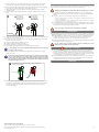
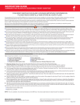
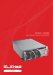
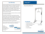
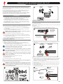
COMMAND POST ADJUSTABLE HEIGHT SEAT POST INSTALLATION GUIDE INTRODUCTION CARBON FRAMES The Command Post seat post provides riders with a way to adjust their saddle height without tools. Although created by the Specialized Suspension team, the Command Post is NOT a suspension seat post. NON-CARBON FRAMES Visit a Specialized authorized dealer if you have any doubt regarding your mechanical proficiency and/or ability to install this product. Specialized recommends that the Command Post be installed by a qualified bicycle mechanic. Please read and understand all the warnings. Failure to follow a warning may result in a catastrophic failure of the Command Post, resulting in serious personal injury or death. This phrase may not be repeated in connection with each and every warning. • SEAT COLLAR I.D. TERMINOLOGY Power position: When the Command Post is at full height. Used when full power is needed, such as climbing a long, steep hill or riding a smooth, flat section. This position provides the full 100mm of available seat post height. Cruiser position: When the Command Post is in the middle position. Used for pedaling on undulating terrain. This position is 35mm below the Power position. Descender position: When the Command Post is at its lowest position. Used for riding downhill/freeride terrain. This position is 100mm below the Power position. Remote Lever: Used to actuate the Command Post. INSTALLATION Take the following items into consideration before installing and using the Command Post. The air pressure in the Command Post is factory set to 25 psi. Air pressure determines the speed at which the Command Post rises. See SETUP AND USE for more information. The Command Post is 30.9mm in diameter. Prior to installation, ensure that this diameter conforms to the diameter of the seat tube. INSTALLING THE REMOTE LEVER The remote lever is connected by cable to the Command Post. A left-handed remote lever ships with the Command Post; however, the remote lever can be positioned on either side of the handlebar, if desired. NOTE: If saddle is already installed, rotate the saddle out of the way, leaving the saddle head lever exposed. To install the remote lever: 1. Determine which side the remote lever will be installed on (see fig. 3). 3 LEFT-HANDED REMOTE LEVER WARNING! Incorrect sizing interface can result in Command Post slippage or failure, causing serious personal injury or death. (CAN BE MOUNTED ON RIGHT SIDE) LEFT GRIP DEVICES (BRAKE, SHIFTER) The Command Post should not have any play inside the frame. The Command Post should slide into the seat tube in a straight, smooth fashion. The seat collar should be positioned so that the slot faces forward to minimize dirt contamination from the rear wheel. RIGHT-HANDED REMOTE LEVER (NOT INCLUDED) If the Command Post exhibits any fit and/or torque issues, it is recommended that the fit tolerance be verified by a Specialized Authorized Dealer. 1. On non-carbon frames only, grease the seat tube I.D. and Command Post O.D. (see fig. 2). 2. Slide the Command Post into the seat tube. 3. Adjust the Command Post to approximate height for proper leg extension. The Command Post ships in the Power (full height) position. While in the Power position, determine saddle height like you would a standard seat post. i RIGHT GRIP DEVICES (BRAKE, SHIFTER) INSTALLING THE COMMAND POST 2. Unscrew the hex on the remote lever using a 4mm hex key, and lightly grease the clamp I.D. (see fig. 4). 4 CARBON HANDLEBARS NON-CARBON HANDLEBARS NO GREASE! REMOTE LEVER I.D. Leave the Command Post in the Power position during installation. This will ensure that the cable housing is at the correct length. 4. Adjust seat collar torque to recommended setting (see fig. 2). i IMPORTANT! Recommended torques in this manual are specific for the Command Post. Consult the bicycle owner’s manual for recommended torque. Always use lower torque recommendation. 4MM WARNING! Only use seat collars approved by Specialized with the Command Post. Use of an unapproved seat collar may result in slippage and potential damage of the Command Post. 15 in-lbf (1.7 N-m) The following 30.9 collars have been tested and recommended: Specialized fixed and Q/R collars NOTE: Do NOT apply grease if the remote lever is to be installed on carbon handlebars. Salsa Flip-Lock Q/Rs Please visit www.specialized.com for future approved collars. NOTE: Do not overtighten. Use only hand pressure on Q/R lever. Only use enough tension to keep the post from slipping. If you are having slipping issues, friction compound pastes or talc powder can be used on aluminum and carbon frames. WARNING! Seat collar torque requirements can vary depending on the specific frame and seat clamp used. Exceeding the max specified torque limit (see fig. 2) can result in damage to the Command Post and/or frame. Consult an authorized dealer for additional information. 3. Clamp the remote lever on the handlebar, ensuring that the remote lever is the handlebar device closest to the stem (see fig. 3). Before installing and tightening the hex screw, operate the remote lever to ensure it doesn’t impede on other devices already on the handlebar, such as shifters and brake levers. 4. Screw the hex on the clamp and torque to 15 in/lbs. using a torque wrench and a 4mm hex key (see fig. 4). 5. Insert the cable through the slot on the remote lever. Pull through until the cable head rests in the slot (see fig. 5). 6. Insert the cable into the 90-degree pipe, making sure to insert the cable through the non-grommeted end (see fig 5). 5 1 b CABLE TO SEAT POST RUN CABLE THROUGH 90-DEGREE PIPE NON-GROMMETED END a BOLT NUT WEDGE NUT AND RAIL CLAMP ASSEMBLY RAIL CLAMP FERRULE c INSERT CABLE INTO NON-FERRULE END OF CABLE HOUSING d ALIGN ARROWS TAB SLOT INSERT CABLE THROUGH SLOT SLOT PULL CABLE UNTIL CABLE HEAD RESTS IN SLOT CABLE HEAD (con’t.) 7. Insert the cable into the non-ferrule end of the cable housing. Pull the cable taught, making sure the housing properly interfaces with the 90-degree pipe (see fig. 5). 8. Run the cable through the barrel adjust on the Command Post. Pull the cable and guide the ferrule on the cable housing into the barrel adjust (see fig. 6). 9. Slide the cable between the lever and hex nut/washer and pull the cable end with needlenose pliers. 10. While keeping the cable taught, tighten the hex nut with a 3mm hex key wrench (see fig. 6). 6 a b PULL THE CABLE AS YOU GUIDE THE FERRULE INTO THE BARREL ADJUST PULL THE CABLE TIGHT WITH PLIERS, THEN TIGHTEN THE HEX NUT/WASHER WITH A 3MM HEX KEY SETUP AND USE The Command Post provides the rider with a simple and convenient way to change saddle height without tools and, sometimes, without having to get off the bike. Adjusting the Command Post position while riding may result in loss of control. Check cable tension if the Command Post suddenly rises or lowers while riding. Ideally, there should be about 1mm of play between the cable ferrule and the barrel adjust. The remote lever is used to change the height of the Command Post: »» To move the saddle up, press the remote lever and guide the saddle upward to either the Cruiser or Power position. »» To move the saddle down, slowly unweight the saddle, press the remote lever and guide the saddle to the Cruiser or Descender position. The Command Post uses an air spring to propel the saddle upwards. The pressure in the Command Post is factory set to 25 psi (1.72 bar). Specialized recommends that body weight be used to guide the saddle up or down. BARREL ADJUST 3MM Never exceed 35 psi (2.41 bar) in the Command Post air chamber. MAINTENANCE CABLE FROM REMOTE LEVER 11. Cut off excess cable with cable cutters, leaving about 1/4” past the hex key/washer. Place a cable tip on the end of the cable. 12. Press the remote lever and make sure the end of the cable and cable tip do not interfere with any of the parts (see fig. 6). 13. Grease the saddle clamp mechanism (see fig. 1). 14. Install the saddle in the clamp mechanism. 15. Adjust the saddle to the desired fore-aft position. 16. Torque saddle head clamp assembly to 120 in-lbf (13.5 N-m) (see fig. 1). i To avoid damage to the seat post/saddle assembly, align the arrows on the bolt and the rail clamp (see fig. 1). 17. Raise the saddle to the Power position, then readjust the Command Post to proper height, if necessary. i Verify cable housing length and check full range of Command Post travel. Make sure the cable housing does not interfere with any bicycle components. In the Power position the cable housing should enter the barrel adjust in a straight trajectory, and the ferrule should have approximately 1mm of play between itself and the barrel adjust (see fig. 7). 7 IN THE POWER POSITION, THE CABLE HOUSING NEEDS TO ENTER THE BARREL ADJUST IN A STRAIGHTFORWARD MANNER. Routine maintenance of the Command Post will provide years of trouble-free performance. Before every ride: Clean the exposed portion of the Command Post shaft with a rag. Every 3 months: Check air pressure, or sooner if you notice a significant decrease in saddle movement speed. Use a standard shock pump to check and increase/ decrease air pressure between the 20 to 30 psi (1.38 to 2.07 bar) range. After 1 year or 150 hours: Have your local Specialized authorized dealer inspect and, if necessary, service the Command Post. The air chamber must be fully discharged before performing any service. Discharge the air chamber in the Power position. ADDITIONAL WARNINGS The Command Post is marked with a minimum insertion line. This is the minimum amount of insertion required for the Command Post to remain structurally safe. However, some frames require additional insertion to ensure that the frame remains structurally sound as well. The base of the Command Post should extend far enough into the seat tube to extend below the underside of the top tube. Specialized Authorized Dealers: Before conducting any service or inspection of the internal parts, make sure the Command Post is at full height (Power position) and completely release all air pressure from the air chamber. WARRANTY For the warranty provisions of this product, please visit http://www.specialized.com. 1MM OF PLAY 18. Using the enclosed zip-ties, secure the cable housing along the length of the top tube, if possible. The cable housing should be oriented in smooth arcs as it leaves the remote lever and as it approaches the saddle head, while maintaining the 1mm of play as it enters the barrel adjust. SPECIALIZED BICYCLE COMPONENTS 15130 Concord Circle, Morgan Hill, CA 95037 (408) 779-6229 Please note that this document is subject to change for improvement without notice. Rev. D, October 2008 2 of 2