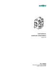
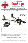
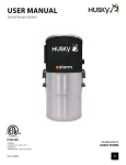
1
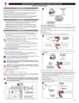
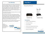
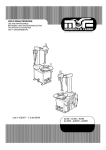
Your Warranty PneuLift™ If a product purchased from Pneumex does not operate properly, Pneumex will repair or replace it at no charge, for up to one year from the date shipped. In the course of repair or replacement, Assembly Manual Pneumex may send you written recommendations on how to prevent a problem from occurring again. Pneumex reserves the right to withdraw this warranty if recommendations are not followed. The customer is responsible for freight charges both to and from Pneumex in all cases. This warranty does not apply to compressors which are covered by the compressor manufacturers. This warranty is exclusive and is in lieu of all other warranties whether written, oral or implied, including the warranty of fitness for any particular purpose. Pneumex liability is in all cases limited to the replacement price of its product. Pneumex shall not be liable for any other damages, whether indirect, consequential, or incidental arising from the sale or use of its products. Pneumex sales personnel may modify this warranty, but only by Key Benefits signing a specific written description of any modifications. Eliminate fear of falling Safety for patient and clinician Freedom for therapists Lifts 150 lbs Use over treadmill Pneumex 2605 Boyer Ave Sandpoint, ID 83864 Pneumex Equipment [email protected] www.pneumex.com 800‐447‐5792 PneuThera Treatment Protocols 32 Patent 5181904 Distributed by Pneumex, Inc. Pneumex, PneuGait Foot Strap, PneuMAP, PneuBack If you find a hole in any point of the air line, you must replace the Chair, PneuWeight and PneuVest are trademarks of line. Tape will not hold during operation of the high pressure Pneumex, Inc. system. Copyright 2003 Pneumex Test the system for proper operation and Unweighting. If problems occur, refer to the troubleshooting guide in this manual. All rights reserved If problems persist, call Pneumex, Inc. at 800‐447‐5792. Visit our web site at www.Pneumex.com Pneumex, Inc. 2605 North Boyer Ave. Sandpoint, ID 83864 Phone 208‐265‐4105 Fax 208‐265‐9651 E‐mail [email protected] Rev 014 Revised Feb 26, 2014 Genuine Pneumex Equipment 2 31 Attaching Air Contents Before using the air compressor, read the instructions supplied by the manufacturer. Preface ‐‐‐‐‐‐‐‐‐‐‐‐‐‐‐‐‐‐‐‐‐‐‐‐‐‐‐‐‐‐‐‐‐‐‐‐‐‐‐‐‐‐‐‐‐‐‐‐‐‐‐‐‐‐‐‐‐‐‐‐ 5 Push one end of air hose into air fitting on air compressor, route hose to your PneuLift (use a route that is out of the way of foot traffic) you can cut hose to desired length and push hose into air fitting on your PneuLift. Use “T” fitting supplied with unit to route air from your unit to other pneumatic equipment such as a Pneu‐ Back Chair. PneuLift ‐‐‐‐‐‐‐‐‐‐‐‐‐‐‐‐‐‐‐‐‐‐‐‐‐‐‐‐‐‐‐‐‐‐‐‐‐‐‐‐‐‐‐‐‐‐‐‐‐‐‐‐‐‐‐‐‐‐‐ 6 Turn the Select Mode switch on the control panel to Off to retract the Unweighting bar's 1. Holes are in base strap if you choose to bolt to floor for greater stability. 2. Turn on the air compressor and open valve. Refer to the compressor manual for operating instructions. 3. Check for air leaks (hissing) and tighten fittings if neces‐ sary. If the fittings are tight and the leak continues, remove the control panel on the upright and check each connection to determine the source of the leak. (Any loosening caused by shipping is noticeable during initial operation.) Liability Notice ‐‐‐‐‐‐‐‐‐‐‐‐‐‐‐‐‐‐‐‐‐‐‐‐‐‐‐‐‐‐‐‐‐‐‐‐‐‐‐‐‐‐‐‐‐‐‐‐‐‐‐ 5 Indications ‐‐‐‐‐‐‐‐‐‐‐‐‐‐‐‐‐‐‐‐‐‐‐‐‐‐‐‐‐‐‐‐‐‐‐‐‐‐‐‐‐‐‐‐‐‐‐‐‐‐‐‐‐‐‐‐ 7 Contraindications ‐‐‐‐‐‐‐‐‐‐‐‐‐‐‐‐‐‐‐‐‐‐‐‐‐‐‐‐‐‐‐‐‐‐‐‐‐‐‐‐‐‐‐‐‐‐‐‐ 7 Using the Unweighting System ‐‐‐‐‐‐‐‐‐‐‐‐‐‐‐‐‐‐‐‐‐‐‐‐‐‐‐‐‐‐‐ 8 Control Panel ‐‐‐‐‐‐‐‐‐‐‐‐‐‐‐‐‐‐‐‐‐‐‐‐‐‐‐‐‐‐‐‐‐‐‐‐‐‐‐‐‐‐‐‐‐‐‐‐‐‐‐‐‐ 9 Unweighting ‐‐‐‐‐‐‐‐‐‐‐‐‐‐‐‐‐‐‐‐‐‐‐‐‐‐‐‐‐‐‐‐‐‐‐‐‐‐‐‐‐‐‐‐‐‐‐‐‐‐‐‐‐ 10 Exercise Mode ‐‐‐‐‐‐‐‐‐‐‐‐‐‐‐‐‐‐‐‐‐‐‐‐‐‐‐‐‐‐‐‐‐‐‐‐‐‐‐‐‐‐‐‐‐‐‐‐ 10 Balance Mode ‐‐‐‐‐‐‐‐‐‐‐‐‐‐‐‐‐‐‐‐‐‐‐‐‐‐‐‐‐‐‐‐‐‐‐‐‐‐‐‐‐‐‐‐‐‐‐‐ 11 PneuVest ‐‐‐‐‐‐‐‐‐‐‐‐‐‐‐‐‐‐‐‐‐‐‐‐‐‐‐‐‐‐‐‐‐‐‐‐‐‐‐‐‐‐‐‐‐‐‐‐‐‐‐‐‐‐‐‐‐‐ 12 Maintenance ‐‐‐‐‐‐‐‐‐‐‐‐‐‐‐‐‐‐‐‐‐‐‐‐‐‐‐‐‐‐‐‐‐‐‐‐‐‐‐‐‐‐‐‐‐‐‐‐‐‐‐‐‐ 14 Air Compressor‐‐‐‐‐‐‐‐‐‐‐‐‐‐‐‐‐‐‐‐‐‐‐‐‐‐‐‐‐‐‐‐‐‐‐‐‐‐‐‐‐‐‐‐‐‐‐‐‐‐‐ 15 Replacing the Control Panel ‐‐‐‐‐‐‐‐‐‐‐‐‐‐‐‐‐‐‐‐‐‐‐‐‐‐‐‐‐‐‐‐‐‐‐ 16 Replacing Air Hose ‐‐‐‐‐‐‐‐‐‐‐‐‐‐‐‐‐‐‐‐‐‐‐‐‐‐‐‐‐‐‐‐‐‐‐‐‐‐‐‐‐‐‐‐‐‐ 17 Replacing Cylinder ‐‐‐‐‐‐‐‐‐‐‐‐‐‐‐‐‐‐‐‐‐‐‐‐‐‐‐‐‐‐‐‐‐‐‐‐‐‐‐‐‐‐‐‐‐‐‐ 18 Replacing Unweighting Bar and Cable ‐‐‐‐‐‐‐‐‐‐‐‐‐‐‐‐‐‐‐‐‐‐ 19 Troubleshooting ‐‐‐‐‐‐‐‐‐‐‐‐‐‐‐‐‐‐‐‐‐‐‐‐‐‐‐‐‐‐‐‐‐‐‐‐‐‐‐‐‐‐‐‐‐‐‐‐‐ 20 Safety Requirements ‐‐‐‐‐‐‐‐‐‐‐‐‐‐‐‐‐‐‐‐‐‐‐‐‐‐‐‐‐‐‐‐‐‐‐‐‐‐‐‐‐‐‐‐ 21 30 3 Specifications ‐‐‐‐‐‐‐‐‐‐‐‐‐‐‐‐‐‐‐‐‐‐‐‐‐‐‐‐‐‐‐‐‐‐‐‐‐‐‐‐‐‐‐‐‐‐‐‐‐‐‐‐‐ 22 Final Assembly Description and Use ‐‐‐‐‐‐‐‐‐‐‐‐‐‐‐‐‐‐‐‐‐‐‐‐‐‐‐‐‐‐‐‐‐‐‐‐‐‐‐‐‐‐‐‐‐‐ 23 Components ‐‐‐‐‐‐‐‐‐‐‐‐‐‐‐‐‐‐‐‐‐‐‐‐‐‐‐‐‐‐‐‐‐‐‐‐‐‐‐‐‐‐‐‐‐‐‐‐‐‐‐‐‐‐ 23 1. Pull the Unweighting bar and cable out through the top of upright. PneuLift Parts ‐‐‐‐‐‐‐‐‐‐‐‐‐‐‐‐‐‐‐‐‐‐‐‐‐‐‐‐‐‐‐‐‐‐‐‐‐‐‐‐‐‐‐‐‐‐‐‐‐‐‐‐‐ 24 2. Remove the 3/8 in. x ¾ in. button head bolt form the top of upright. Unpacking ‐‐‐‐‐‐‐‐‐‐‐‐‐‐‐‐‐‐‐‐‐‐‐‐‐‐‐‐‐‐‐‐‐‐‐‐‐‐‐‐‐‐‐‐‐‐‐‐‐‐‐‐‐‐‐‐‐ 25 3. Position the header assembly across the chairs. Installation ‐‐‐‐‐‐‐‐‐‐‐‐‐‐‐‐‐‐‐‐‐‐‐‐‐‐‐‐‐‐‐‐‐‐‐‐‐‐‐‐‐‐‐‐‐‐‐‐‐‐‐‐‐‐‐‐‐ 25 4. Remove the 3/8 in x ¾ in. button head bolts and washers. Ceiling Height ‐‐‐‐‐‐‐‐‐‐‐‐‐‐‐‐‐‐‐‐‐‐‐‐‐‐‐‐‐‐‐‐‐‐‐‐‐‐‐‐‐‐‐‐‐‐‐‐‐ 25 5. Pass the Unweighting bar and cable through the hole in the header beam, through the cable keeper, over the rollers, and back down through the center hole. Remove Black Hose ‐‐‐‐‐‐‐‐‐‐‐‐‐‐‐‐‐‐‐‐‐‐‐‐‐‐‐‐‐‐‐‐‐‐‐‐‐‐‐‐‐‐‐‐‐‐ 26 Assembly ‐‐‐‐‐‐‐‐‐‐‐‐‐‐‐‐‐‐‐‐‐‐‐‐‐‐‐‐‐‐‐‐‐‐‐‐‐‐‐‐‐‐‐‐‐‐‐‐‐‐‐‐‐‐‐‐‐‐‐ 27 6. Tighten all bolts securely. Tools Required ‐‐‐‐‐‐‐‐‐‐‐‐‐‐‐‐‐‐‐‐‐‐‐‐‐‐‐‐‐‐‐‐‐‐‐‐‐‐‐‐‐‐‐‐‐‐‐‐‐‐‐ 27 Final Assembly ‐‐‐‐‐‐‐‐‐‐‐‐‐‐‐‐‐‐‐‐‐‐‐‐‐‐‐‐‐‐‐‐‐‐‐‐‐‐‐‐‐‐‐‐‐‐‐‐‐‐‐‐ 29 7. Set control to Balance mode. Attaching Air ‐‐‐‐‐‐‐‐‐‐‐‐‐‐‐‐‐‐‐‐‐‐‐‐‐‐‐‐‐‐‐‐‐‐‐‐‐‐‐‐‐‐‐‐‐‐‐‐‐‐‐‐‐‐ 30 8. Raise the upright and header assembly to a vertical position. Warranty ‐‐‐‐‐‐‐‐‐‐‐‐‐‐‐‐‐‐‐‐‐‐‐‐‐‐‐‐‐‐‐‐‐‐‐‐‐‐‐‐‐‐‐‐‐‐‐‐‐‐‐‐‐‐‐‐‐‐‐ 32 9. Insert the 4 (3/8 x 1/2) button head bolts in the base and tighten securely. For proper stability, make sure the stabilization bolt is securely installed in the header beam. Make sure the control is set to Balance mode. 4 29 4. Place upright in base, with the control panel facing out, aligning the pivot bolt with correct height adjustment hole. Preface This manual contains the operating instructions and service re‐ 5. Lay the uprights on the chairs. quirements for the PneuLift Unweighting system. The manual is 6. Tighten the pivot bolts. designed for use by clinical staff use and it is expected that the cli‐ 7. Repeat steps 2‐6 for each base and upright. nicians will instruct their patients and clients in the proper use of 8. Loosen the two 3/8 in. x ¾ in. button head bolts on each base. 9. Fit base straps on floor between bases. Replace bolts and tighten. 10. Base Strap may go on now or after Final assembly. the system and its accessories. Please read the manual carefully, noting the Safety Requirements before using the PneuLift Un‐ weighting system. Liability Notice Failure to follow the conditions set forth below shall absolve Pneumex, Inc. from any responsibility for the safety, reliability, and performance of this equipment. Each operator must read the operator manual in full before Uprights go here using‐ the product for the first time. Each independent user must be instructed in the proper use of the system and its accessories. The electrical wiring within the system's settings, and the electri‐ cal installation of the compressor must comply with the applicable Base strap local or provincial requirements. The equipment must be used in accordance with the instructions for use. It is suggested operators Base of PneuLift receive approved training and certification from Pneumex, Inc. or their designee before operating the equipment. Please call Pneumex at 800‐447‐5792 to find out more about our training and certification programs. 28 5 Assembly PneuLift™ The PneuLift™ Unweighting system uses pneumatic power provided by a small compressor and the PneuVest™ to support the patient. The PneuLift’s™ 0 to 150 lb. Unweighting range allows the patient to perform low‐impact kinetic exercises in an upright, functional position. Activities such as walking, running, stair climbing, jumping and balance may all be performed safely while unweighted. If a patient loses their balance or starts to fall the PneuLift™ systems Balance Mode will support the patient’s entire body weight. The center of the Unweighting system is the PneuVest™. This Unweighting harness fits the patient like a snug vest with a strap positioned on the buttocks. The vest allows the patient to exercise in an upright, controlled and safe position. It effectively grips the body to support all or part of the patients weight. 6 Consider Use The type of exercise equipment used under the system affects the required height. For example, if you are using a treadmill whose walking surface is 6 inches (15.2 cm) from the floor, you should add 6 inches (15.2 cm) to the frame height. Tools Required 7/32 x 6 in. hex key (provided). Air line “T” plus 40’ hose (provided). 2 chairs (or similar stable objects approximately 18 in.) 1. Place the bases facing the same direction, with the open face closest to the wall, about 41 in. (1 m) apart. 2. Loosen the two 3/8 in. x ¾ in. button head bolts on each base top. 3. Place chairs about 65 in. away from the bases. 27 Remove Black Hose Before Use Indications for use 1. Remove the plastic wrap from base of upright and pull air fit‐ Acute and Chronic Backs Back Pain Ruptured Disc Herniated / Bulged Chronic Headache / Upper Thoracic Tightness Post Surgical Osteoporosis Knee, Hip, & Ankle Injury Orthopedic Patients Cardiovascular Overweight Patients Respiratory Ailments Neurological Patients Assist in lifting wheelchair Patients ting out the bottom (should have short black hose attached). 2. Remove one nut from the air fitting, then insert black hose and fitting through air inlet hole in upright top hole. See Fig. 3 Note: Black hose not shown in Fig. 3 Air inlet Air fitting (Inlet hole) Air hose (inside post) Post end Control panel power plug Fig. 3 3. Slip nut (removed in step 2) over black hose and while pulling firmly on black hose tighten nut on air fitting. Contraindications 4. Black hose can now be removed by compressing lock ring on air fitting. See Fig. 4 Tumors on the spine Respiratory conditions which are exacerbated by pressure on the rib cage. Black hose Pull hose out of fitting This can sometimes be compensated for by taking more weight through the legs or by using a thoracic vest Compression ring Fig. 4 Bulkhead air fitting 26 Push down on compression ring 7 Using the Unweighting System Unpacking 1. Turn on the air compressor. Refer to the compressor manual for op‐ erating instructions. Tools Required-Sharp knife Cut all tape and remove corrugated and plastic wrapping. Do not remove the plastic surrounding the air cylinder inside the upright. 2. Gently pull out he unweighting regulator knob and turn counter‐ clockwise until it comes to a stop. 3. Position the mode selector switch in the OFF position. 4. WARNING: Ensure that all personnel and equipment are clear of the unit as sudden system pressurization can cause the cable assembly to retract rapidly. 5. Fit the vest correctly to the subject and connect the vest securely to the Unweighting bar. 6. Turn the Select Mode knob to Exercise. 7. Pull out the Unweighting knob and gradually turn it clockwise until the gauge shows the desired lift. Have the person move up and down a little and confirm that the gauge is at the desired setting. 8. For activity up to 30 inches (76.2 cm) vertical motion, leave the Select Mode knob in Exercise. For activity less than 6 inches (15.2 cm) vertical motion, set the Select Mode knob Balance. 9. To re‐weight, turn the Select Mode knob to Exercise, then turn the Unweighting knob completely to the left. Do not force the knob (to re ‐weight quickly, turn the Select Mode knob to Off). 10. When the Unweighting gauge reaches zero psi, turn the Select Mode knob to Off. 11. Disconnect the person from the system and remove the vest. 8 Remove the operator/service manual, air hose, and vest and store them temporarily in a safe place. The Unweighting bar and the air hose are tucked inside the up‐ rights for safety during shipping. Installation Electrical Requirements The compressor ( if ordered) requires an appropriate AC line for charging. Refer to the manual supplied by the compressor manufacturer for electrical requirements. Ceiling Height Before assembling, determine how high to make the system. The series of holes in the bases provides 4 height options, progressive‐ ly changing by 3 inches (7.6 cm). The total height on a system can be set to any of the following.: 7 ft 10 in (2.41m) 8 ft 1 in (2.49 m). 8 ft 4 in (2.57 m). 8 ft 7 in (2.64 m) For installation, the ceiling height should be at least 1 inch (2.5 cm) higher than the final system height. At minimum height (uprights fully inserted into the base), the system accommodates users up to 6 feet 4 inches (1.93m) tall. 25 Control Panel PneuLift™ Parts Two base supports: package includes instructions, installation hardware, air hose, and vest. Two upright posts with air hose, and Unweighting bar. One header beam assembly One vest The control panel is located on the upright. It has an weighting pressure gauge and two controls. Gauge/Control Un- Function Unweighting pressure Indicates the number of pounds/ gauge Header kilograms the system is Un‐ Unweighting regulator Gradually increases (+) or de‐ Unweighting bar (Cable Assembly) knob creases (‐) the amount of Un‐ Mode selector switch Provides choices of Exercise, Bal‐ ance, or Off (OFF‐EX‐BAL) Control panel PneuVest Exercise Mode Exercise mode lets the user perform long vertical movements, such as jumping or stair climbing, with consistent Unweighting over the full range of movement. All Unweighting adjustments are done in Exercise mode. Balance Mode Upright Base Base Strap 24 Balance mode lets the user perform exercises involving less vertical movement, such as walking, running, or balance activities, without fear of falling. The system supports the entire body weight during loss of balance, allowing a fall of no more than three to six inches. Balance mode frees the assistant to use both hands while assisting the user. OFF OFF mode releases the air from the system quickly. This mode can be used to re‐weight a person quickly if desired. 9 Unweighting Description and Use Exercise Mode The PneuLift Unweighting system supports a person's body weight during exercise. The pneumatic system lifts, or “unweights, “ the user, reducing the amount of strain weight places on the body. As the user becomes stronger and can tolerate additional stress on the body, the weight can be adjusted to make the body do more work. The system can be used with most types of exercise equipment, including, but not limited to: treadmills, steppers, bicycles, mini‐ trampolines, and balance boards. Turn the Pneu‐Weight™ Mode selector switch to exercise mode and using the regulator dial in the desired amount of weight to be unweighted. Note: the usual protocol to determine the amount of weight to be removed is “pain‐free” or “pain tolerable”. This will usually be around 30% to 50% of body weight. Components The exceptions are: Post surgical‐in many cases will be per‐ centage weight bearing dictated by M.D. The PneuLift components include a frame with pneumatic con‐ trols and Unweighting bar, an air compressor, and an exercise vest. Each unit comes with: Installation hardware Neurological or spinal cord injury (SCI)‐ to stabilized or normalized upright state. Quite often this will entail removal of close Operator/service manual PneuVest to 100% of body weight to assist in lift and then adding weight back to patient as desired. Sciatica ‐ quite often require 70% + of body weight off in early stages. Exercise Mode 10 23 Balance Mode Specifications The majority of treadmill activities will be done in the balance mode. The exercise mode is used for adjusting the amount of Capacity 0-150 lb oscillation than balance mode allows, e.g. retraining sit to stand Operating Modes: Exercise 0‐30 in vertical motion pneumatic stop limited down motion Balance or step up/step down activity. You may want to show the patient they cannot fall in the system. Floor space (w x d) 42 in x 50 in Height O.D. 7 ft 10 in to 8 ft 7 in Air hose OD./I.D. 0.25/0/17 Compressor air fitting Unweighting when performing activities that require more vertical ¼ MPT Compressor power Refer to compressor manual supplied by requirements compressor manufacturer. Weight 90 lb Shipping Weight 92 lb Balance Mode To decrease the distance the system will allow a patient to come down: More weight can be removed before switching to balance. Patient can stand on their tiptoes or a stool before switching to balance 22 11 PneuVest Safety Requirements A correctly fitted PneuVest vest is the key to successful Un‐ weighting. When choosing a vest, select one that corresponds to the user’s waist size, not to the chest size. The vests are color‐ coded. (See the PneuVest instruction booklet) Read this manual in full before using the PneuLift. Do not start the PneuLift until you are sure the vest is properly secured. Do not operate this equipment in the presence of flamma‐ ble anesthetic mixtures. To avoid potential safety problems, use parts and acces‐ sories that meet specifications given in this manual. The compressor must be on an appropriate electrical circuit. Read the manual supplied by the compressor manufacturer be‐ fore using the compressor. Before each use, inspect the air tubing for damage, pinched areas, and leaks. Inspect the power receptacle for damage. Do not use if the integrity of these items is questionable. Check all rollers for any wear or groves Check each cable for any rough spots or signs of fraying. With increased use of the PneuLift, we are recommending a weekly inspection of cables, particularly in the area over the rollers, for signs of fraying. Attaching the Vest to the Unweighting Bar 1. Each shoulder strap on the vest has a D‐ring that attaches to the Unweighting bar. Adjust the upright posture of the person being unweighted by moving the D‐ring back or forth on the straps. For example, to flex the person, slide the D‐ring backward. To extend the person, slide the D‐ring forward. 2. Attach D‐rings to the safety snaps on the Unweighting bar. 3. Use the control panel to unweight. Attaching to bar for Wheelchair Users You may need to use extension chains to connect wheelchair users to the Unweighting bar. 1. Place the wheelchair under the bar (for treadmills, you may need to use a ramp to place the person under the bar.) 2. Pull the bar down and connect the chain extension to the unweighting bar. 3. Attach the D‐rings securely to the clips on the extension. 4. Unweight the person from the chair and remove the chair. Adjust the extension as needed. 12 Failure to follow these guidelines can produce a serious or possibly fatal hazard or other injury. 21 Troubleshooting Before Unweighting anyone, be sure the waist belt is snug and that the safety snaps (carabineers) are closed completely. Problem System will not unweight Possible System Leak Solution Check for leaks. Replace as necessary Compressor not set to correct psi Set compressor to 70 psi Kinked hose Check hoses for kinks System unweights only partway Subject weights more than 200 lb. (91 kg) Increase the compres‐ sor setting to 120 psi. The maximum lift is 350 lb (159 kg) Installed new control panel, but system still leaks in Balance mode Fittings are leak‐ ing Reseat or replace the fittings Pneumatic cyl‐ inder faulty Replace the pneumat‐ ic cylinder In Exercise mode, Air compressor Unweighting bar will not disconnected or retract leaking Installed new control panel, but system does not work Wrong psi Hoses not con‐ nected or connect‐ ed incorrectly 20 Check connections and air hose Check compressor setting Check hoses inside control panel. Be sure they are connected securely to the proper fitting. After Unweighting, ask the subject if the vest feels uncomfortable. Be sure that the vest is not wedged into the underarms and that it does not restrict breathing. Be sure that the leg straps are not tight enough to restrict circulation in the legs. Readjust the vest as nec‐ essary. Correcting Vest Problems If the vest rides up under the arms, re‐weight and pull the vest down. Have the person tighten the abdominal muscles, then re‐ tighten the waist straps and leg straps. The JO straps can help to keep the vest in place. See PneuVest manual for instructions. If the chest strap is too tight during exercise, loosen. If the leg cuffs ride up, re‐weight if necessary and replace the cuff centering the front leg strap on the thigh. Some people like the cuff higher up on the thigh, but for most patients the cuff is more comfortable just above the knee. Pull the strap around cuff snugly. If the leg straps are too tight, or seem to pinch try changing the position higher or lower on the thigh. PneuVest Vectors with IT Strap 13 Replacing the Unweighting Bar and Cable Maintenance Cleaning Replace the Unweighting bar or cable if it appears frayed or worn. Use a soft cloth rinsed in warm water to clean the exterior surfaces. When needed, machine‐wash the vest on gentle cycle using regular detergent and cold water. Hang to dry. Disinfections Use procedures established for your facility. The vest can be washed with a mixture of water and disinfectant such as Lysol or equivalent. Do not use bleach on the vest—the color will fade. 1. Remove the control panel. 2. Pull the cotter pin and the clevis pin from the top of the pneu‐ matic cylinder. Cable will fall as soon as you pull the clevis pin. Use Caution not to drop any parts into post. 3. Remove the cable by pulling it out from the top of the upright. 4. Install the new cable down from the top of the upright. 5. Reinstall the clevis pin and the cotter pin. Schedule Service 6. Replace the control panel. No scheduled service is required. See Preventive Maintenance be‐ low. For service, call Pneumex: USA & Canada: 800‐447‐5792 International: 208‐265‐4105 Preventive Maintenance Routinely check the air hose, air fittings, and compressor for leaks. Check the Unweighting bar and cable for loose wires or fraying. 14 19 Replacing Cylinder If you have replaced the control panel and the system still leaks air while in Balance mode, you may need to replace the pneumat‐ ic cylinder. A leak from the cylinder will be very gradual, with no discernible noise. Air Compressor Drain the air compressor at lest once a week. For compressor maintenance and service information, refer to the manual sup‐ plied by the compressor manufacturer. 1. Dismantle the entire system and lay the uprights flat on the floor. 2. Remove the control panel. 3. Disconnect the cable from the cylinder. Remove the cotter pin and the clevis pin from the pneumatic cylinder. 4. Use the 7/32 Allen wrench to remove the two bolts near the base that holds the cylinder axle into the upright. 5. Tilt the upright and pull the pneumatic cylinder out through the bottom. 6. Insert a new pneumatic cylinder, attaching it to the cable and reattaching the clevis cotter pins, axle and axle bolts. 7. Replace the control panel. 8. Reassemble the system following the installation in‐ structions. 18 15 Replacing Control Panel Replacing Air Hose 1. Turn off the compressor, make sure air is off to unit. 1. Disconnect the hose from the air fitting on the bottom or top of 2. Remove the screws that attach the control panel to the upright using the 5/32” short arm provided. Refer to the illustration for the remaining steps. 3. Locate the Select Mode switch on the back of the control panel. Fully depress the stainless collar on the top of the Select Mode switch fitting and remove the black hose that goes from the switch to the pneumatic cylinder. 4. Remove the two red hoses from the fittings on the bottom of the Select Mode switch. 5. Remove the clear air hose from the regulator inlet fitting. 6. Slide the clear hose into the regulator inlet fitting and push until it is secure. Slide the black hose from the pneumatic cylinder se‐ curely into the fitting on the top of the Select Mode switch. Slide the two red hoses securely into the fittings on the bottom of the Select Mode switch. The hoses are interchangeable. 7. Turn the compressor on to 100 psi and pressurize the system to check for leaks. 8. Replace the screws and tighten to secure the panel to the upright. the upright. 2. Remove the control panel. 3. Pull out the old hose from the bottom of the assembly and dis‐ card. 4. Feed the air hose down from the control panel to the bottom of the upright. Attach one end of the air hose to the regulator on the control panel and the other end to the air fitting on the bot‐ tom of the upright. 5. Replace the control panel. Gauge Regulator Select Mode 16 17