1
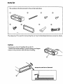
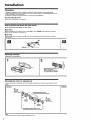
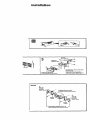
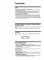
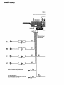
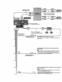
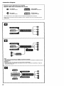
FM/AM
Cassette
Car Stereo
Installation/Connections
XR-C2300X
XR-C2200
Sony Corporation
© 2000
Parts list
The numbers
in the list are keyed to those in the instructions.
O
®
®
®
@
®
®
®
×4
The release key (_) is used for dismounting
the unit. See the Operating
Instructions
Cautions
* Cautionary
notice for handling the bracket O.
Handle the bracket carefully to avoid injuring your fingers.
° Remove the protection
collar @ before installing.
Release the catch lock as illustrated.
manual for details.
Installation
Precautions
* CJhoo_
the
i_st, m_a_ o_ l_
• Avoid
insta[N ng the
in dirge
_u_li_,ht
or
• Use only
the _upplt_l
Mounting
angle
h Ol'Lcm reft;I]y
so that
the _lt
will
not
intel'ferB
wzth
tloz1_al
urdt i_ ar_as subject to d use, dirt, _slve
vibration,
or hJ _
neBr h_ater
duct_.
mo_n_
J_ardware
_F a safe and s_cu_-e instaUatlon.
dri_blg.
temperatures,
su_
_s
adjustment
Adjust
the
ang[_
How
to detach
Before
InstaUlng
mounhng
to le_
ban
__0_.
I
[]
and
the
unit,
attach
detach
the
the
front
front
panel.
panel
To detach
Before
de _c)_iz_
t_e Ero_t p_e[,
b_ su_ to pros
JJ_tle to the leh. and
pull it _ff to'-va='d s you.
[]
Ta
_,
J_re _s _,
then
slide
the
fr_t
panel
a
attach
Attach
part _)
tt_tlJit¢l_ck_.
of the
Mounting
£ront
peunel
to p_rt
_)
of the
u_it
a_ ill ustr_t_l
_d
push
the J_ft _de
into
po_it_on
example
In_lla_lon
Ir_ tl_
dashboard
2
1
bo .
Ught
t
f_..f
n
ry
Plier m
griff_s
po_t assu mr
un_ prm_ _orrl_t_
si n_c_ms_ ir_
Mounting
YOU ma)_
d_aler.
the
_)t
be
able
unit
to bast;sit
in a Japanese
_
u_nlt in
r,onle
car
_ake_
of ]'a]_anese
_:a_
I_ -'.ocha _se,
_onsult
TOYOTA
_,_ny
NISSAN
®
m_x. size
S xB rain
D_si_n
Sxgmm
N_
To Ixev_nt
yo_"
tn_ffu_on,
let.trail
only _vlth
the _;.,Ipplied
$crev*_ _._.
Installation
Fin_
3
parol
Dashboard
Tableau
de
wall
ig nifugl
bord
®
With the UP mrklng
up
Avgc I'inscriptLon
UPvmr_
le halt
NISSAN
max
5×Emm
slz_
Connections
Caution
• This unit is designed for negative ground 1-° V DC operation only.
• Be careful not to pinch any wires between a screw and the body of the caz or this u_t or between any
moving i_rt_ such as fl_eseat railing, etc.
• Before malting connections, di_onnect the ground terminal of the car battery to avoid short drcuits.
• Connect _e yellow and red power input teaclsonly after all other leads have been connected.
• Be sure to connect the red power input lead to the positive 12 V power terminal which i_ energized
when the tgni_on _ is in the acc_ssozT,_it_on.
° Run all ground wires to a common ground point.
• Connect bheye_ow cord to a free car cLrc_t rated higher than the unit's fuse z_lzng. If you connectthis
unit Jn serie_ with other stereo components, the car circuit the" are connected to must be rated higher
than the sum of the individua) component's fu_e rating. If there are no car circuits rated a_ high as the
unit's fuserating, coz_nectthe unit directly to _e battery. If no car c_rcuiteare av_lable for cormecl_ng
this unit, connect the unit to a car cLrcuitrated hi._ er than the u_t'_ fuse rating in sLtCha way that if the
unit blows its fu_e, no other circuits will be cut off.
Warning when installing in a car without ACC (accessory)position on
the ignition key switch
Be sure to press (_
engine.
When you press _
on the unit for two seconds to torn off the clock display aSter turned off the
momentarily,
the dock d_spl_y does not turn off and th_s causes batten,
wear,
Reset button
When the L_st_[at_on and connections are complete,
pen, etc.
be sure to p_s
the reset button with a ball-point
Notes of connection example
Notes on the €ontm/and
povRr supp/y leads
• l_e power antenna control lead (blue) supplies +12 V DC when you turn on the unit.
• When your car has a built-in FM/AM antenna in the rear/side glass, it is necessary to connect the power antenna
control lead (blue) or the accessory power input lead (red) to the power termina I of the extsTing antenna boosten
For details, consult your deale_
• A power antenna Without a relay box cannot be u_ed with th_ uni_
Memo_ hold connection
When the yellow power input lead is €onn_cte_
the ignition switch i_ turned of_
power wi# always be rupplled to th_ memory circuit even when
Notes on speaker connecdon
• Before connecting the speaker;, turn the unit off.
• U_e speakers with an impedance of 4 to 8 ohn_. and with adequate power handling ,apecltle_
Otherwise, the
speaker may be damagect
• Do not connect 11_ terminals of the _peaker system to the car chassis, and do not connect the terminals of the
right speaker with those of the le_ speaker.
• Do not attempt to _onnect the zpeaker_ it_ parallel.
• DO not connect any _tfve speakers (with buitt_n amplifien) to the speaker terminals of the unit. Doing so may
damage the active speakers. Be _ure to connect pesdve speakers to these terminals.
Connection example
Supplied
Foumi a
!
I
XR-C2300X
XR-C2200
Fuse (10 A)
Fusible (10 A)
Blue/white striped
Ray_ bleu/b_an(
White
Gauche
Gray
_ue
Bleu
Gauche
Mauve
c_t
__
to the +12 V power terminal which is en ergi_ed at all times
Be sum to conned the black ground lead first.
Purple
_
Yellow
Jaune
Red
to a me_.al place in the car
first connect the black ground lead, then connect the
yellow and _ power input leads,
_
r_
Black
Noir
_.
Rouge
Supplied with XA-a0
Foumi av_ le XA-C]0
\
Suppl_-_l with the CD/M D changer
Foumi avec le thangeu r de CDIMD
ft'ont a (ar
alltlL_ln_
de I'antenne
de bs voltum
RCA gin acord
(not RCA
supplied)
Cordon
broche
(non foumi)
Blue/white striped
Pray6 bleu/blanc
AMP REM
Max, supply ¢uRent 03 A
Courant ma_ fouml 0,3 A
To AMP REMOTE IN of the optional power amplifier
This connection is only for amplifiers. Connecting any other system may
damage the unit.
to the powlr armmna control kind or power supply kind of antenna
booster amplWmr
Notes
BIU_
Bleu
ANT REM
..._._
• It is not necessary to connect this lead if there is no power antenna or
antenna booster, or with a manually<>perated tele_opi_ antenna.
• When your car has a built-in FM/AM antenna in the reariside glass, see
"Notes on the control and power supply leads."
M_. supply current 0.1 A
Courant max. fourni 0,1 A
to the +12 V power terminal which is ene_jized nt the accessory position of
the ignition key switch
Notes
Red
Rouge
O
• ff there is no accessory position, connect to the +12 V power (battery)
terminal wh_J_ is energized at all ames.
Be sure to connect the black ground to It ftrst.
• When your car has a bullt-ln FM/AM antenna in the reariside glass, see
"Notes On the ,ontrol 8nd power supply le_d$."
Connection
diagram
Equipment
Appareils
used
utilis#s
in illustrations
clans
Fron
Hiut-pa t |p#ker
dgur
les
(not
supplied)
illustrations
(non
fournis)
power
amplifier
Arnpl_ical_ur
frontal
Rear sl_ak_r
Hau_pafleurl_imm
FOr
connecting
Pans le ,_s
indispenxable.
two
du
Dr mole
raccordernent
cha_r_,
de
deux
th_
source
Se_r
¢l_n_u_
ou plus.
before
arnp_f_r
connecting
_ncl do not
avant
_nn_er
XA-C_O
(_o_i_nal)
le s_cteur
de
de
¢D/MD
changer
Chmng_r
de
puimnce
CD/MD
J, n_esx_ry.
source
XA-C30
_ptionnel)
_t
Q
Q
No_e5
- Be sure to conne_:
o If you _nr_ect
_n
¢l*ta_ivefe_
Remarqu_
4 p.ac_'ordez
b_p
sor_r_
B
0
d'_bo_
_st
the ground
optional
_ver
I_ 1_1 d_
d_u_tive.
cord
n_asse
de
the amplifier.
us_ the built-in
I'_n_plifi_ateu_
t)mplifler,
the
beep
sound
will
Sony Corporation
Printed
in USA
SonyOline
http://www.world.sony.com/