1
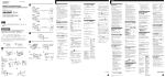
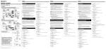
Connection diagram Diagrama de conexión スuク sアオケマ Equipment used in illustrations (not supplied) Equipo utilizado en las ilustraciones (no suministrado) エ。ケマ、、ィマ・ホェコクヒクm。]ォDェ™ーe。^ Active subwoofer Altavoz activo de potenciación de graves ヲウキスカWァCュオエュチnセケ CD/MD changer Cambiador de discos compactos/minidiscos CD/MD ツ犇ォセケ Power amplifier Amplificador de potencia ・¥イvゥ jセケ Front speakers Altavoces delanteros ォeエュチnセケ For connecting two or more changers, the source selector XA-C30 (optional) and the BUS cable RC-61 (1 m) or RC-62 (2 m) (optional) are necessary. Cuando desee conectar dos o más cambiadores, necesitará un selector de fuente XA-C30 (opcionales) y un cable BUS RC-61 (1 m) o RC-62 (2 m) (opcionales). ウsアオ2ャ[ゥホ2ャ[・H、Wツ 犇ォセケョノ。A・イカキィマ・ホュオキスソ ワセケXAC30。]・tチハォ~。^。A・H、ホBUSォHョァツ 犂セィtイホケqニlRC-61。]1m。^ ゥホRC-62。]2m。^。]・tチハォ~。^。C Rear speakers Altavoces traseros ォ盒ュチnセケ A Changer Control Audio Master TV monitor Monitor de TV ケqオ ハオ ケ BUS AUDIO IN Installation/Connections Instalación/Conexiones ヲwクヒ。™スuク sアオ SUB OUT BUS CONTROL IN LINE OUT REAR LINE OUT FRONT WX-C770 Sony Corporation 1998 B BUS CONTROL IN Parts for installation and connections Componentes de instalación y conexiones ヲwクヒ、ホスuク sアオ・ホウ。・ TV tuner unit Unidad de sintonizador de TV ケqオ ユソモセケ XT-40V BUS AUDIO IN Printed in Japan The numbers in the list are keyed to those in the instructions. Los números de la lista corresponden a los de las instrucciones. 、Uュアケマェ フェコシニヲrサPサ。ゥ ム、、ェコシニヲrャO、@ュPェコ。C SUB OUT 1 2 3 Source selector Selector de fuente ュオキスソ ワセケ ×8 (incl. 2 reserve) (se incluyen 2 de reserva) 。]・]ャA2ュモウニ・ホェコチウオキ。^ ×1 For NISSAN cars only Sólo para automóviles NISSAN カネセA・ホ NISSAN オPィTィョ ×1 *I-3-859-833-11* (1) Installation Instalación ヲwクヒ Precautions Precauciones ィマ・ホォeカキェセィニカオ •Do not tamper with the four holes on the upper surface of the unit. They are for tuner adjustments to be done only by service technicians. •Choose the installation location carefully so that the unit will not hamper the driver during driving. •Avoid installing the unit where it would be subject to high temperatures, such as from direct sunlight or hot air from the heater, or where it would be subject to dust, dirt or excessive vibration. •Use only the supplied mounting hardware for a safe and secure installation. •No toque los cuatro orificios de la superficie superior de la unidad. Estos orificios son para ajustes del sintonizador que solamente deberán realizar técnicos de reparación. •Elija cuidadosamente el lugar de montaje de forma que la unidad no interfiera las funciones normales de conducción. •Evite instalar la unidad donde pueda quedar sometida a altas temperaturas, como a la luz solar directa o al aire de calefacción, o a polvo, suciedad, o vibraciones excesivas. •Para realizar una instalación segura y firme, utilice solamente la ferretería de montaje suministrada. •・サセ ~ェ ア、Wェコ4ュモ、ユスミ、」ュnカテァヒ。C・Lュフカネィムコ ラァ゙ウN、Hュ ユセ羶ユソモセケ 、ァ・ホ。C •・サセ ミゥ b、」ァォテェ・qセ rセp、ァウB。C •チラァKァ筵サセ bーェキナ、ァウB。Aヲpカァ・ スアオキモョg。Bキxョ e。Bゥホヲヌケミキ・ヲh。A ナシカテ。A・H、ホキ・ゥ _ーハオ・ヲa、陦C •ャー、Fヲw・™ー_ィ」。Aヲwクヒョノスミィマ・ホェ™ーeェコ、uィ 罍C ヲwクヒィ、ォラ、ァスユセ スミヲb20ォラ・H、コスユセ罔wクヒィ、ォラ。C Ajuste del ángulo de montaje Mounting angle adjustment Ajuste el ángulo de montaje a menos de 20°. Adjust the mounting angle to less than 20°. Mounting the unit in a Japanese car アN・サセ wクヒゥ 鬣サイ」ィTィョクフ Montaje de la unidad en un automóvil japonés You may not be able to install this unit in some makes of Japanese cars. In such a case, consult your Sony dealer. When you mount the supplied bracket to this unit, use the supplied screws 1 from this unit and mount to the appropriate mount holes for your vehicle: T (for TOYOTA), M (for MITSUBISHI) and N (for NISSAN). ヲウェコ、鬣サイ」ィTィョ、」ッ爬wクヒ・サセ Cヲbウoコリア。ァホ、U。AスミアzヲVキ aェコ Sony クgセPーモソヤク゚。C Es posible que no pueda instalar esta unidad en algunos automóviles japoneses. En tal caso, consulte a su proveedor Sony. キ zァ筱™ーeェコヲォャ[ヲwクヒィぇサセ ノ。A スミィマ・ホ・サセ ™ーeェコチウオキ1。Aィテ ヲwクヒィこzィTィョェコャロタウヲwクヒ、ユ、W。R T。]・ホゥ TOYOTA。^。AM。]・ホゥ MITSUBISHI。^。A・H、ホ N。]・ホゥ ISSAN。^。C Para montar el soporte suministrado en la unidad , utilice los tornillos suministrados 1 de esta unidad y móntelo en los orificios de montaje adecuados para el vehículo: T (para TOYOTA), M (para MITSUBISHI) y N (para NISSAN). N T M T M N T T N T N Notes • Do not use excessive force on the buttons of the unit. • Do not push on the display window. • Before mounting, make sure there is nothing on top of the unit. M N オ • 、チ、ナヲb・サセ コォ 荀W・ホ、OケL、j。C • 、チ、ナアターハナ罕ワォフ。C • ヲwクヒォe。Aーネ・イスTォO・サセ コウサ、WィSヲウ・ Notas • No emplee los botones de la unidad con excesiva fuerza. • No ejerza presión sobre el visor. • Antes de realizar el montaje, asegúrese de que no hay nada sobre la unidad. ォナ鬘C NISSAN TOYOTA/MITSUBISHI 1 max. size 1 max. size Tamaño máx.: 5 × 8 mm to dashboard/center console al salpicadero/consola central ヲワサ O。™、、・。アアィ c 5 × 8 mm to dashboard/center console al salpicadero/consola central ヲワサ O。™、、・。アアィ c 5 × 8 mm Tamaño máx.: 5 × 8 mm ウフ、j、リ、o 5。ム8 mm ウフ、j、リ、o 5。ム8 mm This illustration for TOYOTA cars. Esta ilustración es para automóviles TOYOTA. TOYOTA オPィTィョケマ・ワ 1 max. size 5 × 8 mm Existing parts supplied to your car Piezas existentes suministradas con su automóvil 5 × 8 mm Tamaño máx.: 5 × 8 mm Bracket Soporte ヲォャ[ ウフ、j、リ、o 5。ム8 mm Tamaño máx.: 5 × 8 mm Existing parts supplied to your car Piezas existentes suministradas con su automóvil タHィTィョェ™ーeェコウ。・ Note To prevent malfunction, install only with the supplied screws 1. 1 max. size 2 Bracket Soporte ヲォャ[ タHィTィョェ™ーeェコウ。・ Nota Para evitar que se produzcan fallos de funcionamiento, realice la instalación solamente con los tornillos suministrados 1. オ ャーィセ、 o・ヘャGサル。Aヲwクヒョノ・uッ爲マ・ホェ™ーeェコチウオキ1。C ウフ、j、リ、o 5。ム8 mm Connections Conexiones スuク sアオ Caution Precauciones キェN ` •This unit is designed for negative ground 12 V DC operation only. •Before making connections, disconnect the ground terminal of the car battery to avoid short circuits. •Connect the yellow and red power input leads only after all other leads have been connected. •Be sure to connect the red power input lead to the positive 12 V power terminal which is energized when the ignition key is in the accessory position. •Run all ground wires to a common ground point. •Connect the yellow cord to a free car circuit rated higher than the unit’s fuse rating. If you connect this unit in series with other stereo components, the car circuit they are connected to must be rated higher than the sum of the individual component’s fuse rating. If there are no car circuits rated as high as the unit’s fuse rating, connect the unit directly to the battery. If no car circuits are available for connecting this unit, connect the unit to a car circuit rated higher than the unit’s fuse rating in such a way that if the unit blows its fuse, no other circuits will be cut off. •Esta unidad ha sido diseñada para alimentarse con 12 V CC, negativo a masa, solamente. •Antes de realizar las conexiones, desconecte el terminal de puesta a masa de la batería del automóvil a fin de evitar cortocircuitos. •Conecte los cables de entrada de alimentación amarillo y rojo solamente después de haber conectado los demás. •Cerciórese de conectar el cable de entrada de alimentación rojo a un terminal de 12 V positivo que se energice al poner la llave de encendido en la posición para accesorios. •Conecte todos los conductores de puesta a masa a un punto común. •Conecte el cable amarillo a un circuito libre del automóvil que tenga una capacidad superior a la del fusible de la unidad. Si conecta esta unidad en serie con otros componentes estereofónicos, el circuito del automóvil al que se encuentran conectados debe tener una capacidad superior a la de la suma de las capacidades de los fusibles de cada componente. Si ningún circuito del automóvil tiene una capacidad tan alta como la del fusible de la unidad, conecte ésta directamente a la batería. Si el automóvil no dispone de ningún circuito para conectar esta unidad, conéctela a un circuito del automóvil con capacidad superior a la del fusible de la unidad, de forma que si se funde el fusible de ésta, no se interrumpa ningún otro circuito. •・サセ uッ マ爲 ・ホュtキ・アオヲa ェスャyケqキス。C 12 V •ウsアオォe。A・©ゥ゙・hィTィョケqヲタェコアオヲaコン、l。A・HァKオo・ヘオuク C •ャ Mカ筰タヲ qキス篁 ソ Jセノ鬢 スu・イカキヲbゥメヲウィ Lセノ茹 スuウ」ウsアオァケイヲ・Hォ ~ウ皃 sアオ。C +V •ャqキスセノスuーネスミウsアオヲワ 篁 ケqキスコン、l。]クモケqキスコン、lヲbツI、 12 _ーヘウB ゥイァUヲ mず ョノ、~ウqケq。^。C •アNゥメヲウヲaスuウ」ウsアオィ P、@え ヲaツI。C •アNカタヲ ノス篝 uウsアオィ ケjォゥう OタIオキテBゥwョeカqェコ・シヲ ホェコィTィョケqク W。C ュYァ サセ筵MィL・゚ナ 茹 nイユヲィセ 鮹 ロ、ャヲ p。AゥメウsアオェコィTィョケqク eカq・イカキ 、jゥUイユヲィセ OタIオキョeカqェコチ`ゥM。C ュYィSヲウサP・サセ OタIオキテBゥwョeカq、@シヒ、jェコィTィョケqク iQ ク・ホ。A・iァ サセ筵 ェスアオウsアオィ qヲタ、W せ 。C ュYオLセAキ コィTィョケqク i・ホゥ sアオ・サセ Aスミァ サ筵 セ sアオィ jう ゥ サセ OタI オキョeカqェコィTィョケqク W。CウoュシYヒ・。サAセ コォOタIオキソNツ_、]F、。」A ュPゥ チ ツ_ィ 茹 Lケqク C If your car has no accessory position on the ignition key switch — POWER SELECT switch Si el automóvil no dispone de posición para accesorios en la llave de encendido ュYュnヲbィTィョオoーハセ T ィコェノョホ・マィフク — Selector POWER SELECT POWER — SELECT カ}テ The illumination on the front panel is factory-set to be turned on even when the unit is not being played. However, this setting may cause some car battery wear if your car has no accessory position on the ignition key switch. To avoid this battery wear, set the POWER SELECT switch located on the bottom of the unit to the B position, then press the reset button. The illumination is reset to stay off while the unit is not being played. Note The caution alarm for the front panel is not activated when the POWER SELECT switch is set to the B position. La iluminación del panel frontal ha sido ajustada en fábrica para que esté activada aunque la unidad no se encuentre en reproducción. Sin embargo, este ajuste puede provocar cierta descarga de la batería del automóvil si éste no dispone de posición para accesorios en la llave de encendido. Para evitar esto, ponga el selector POWER SELECT, situado en la base de la unidad, en la posición B y, después, presione el botón de reposición. La iluminación estará desactivada cuando la unidad no se encuentre en reproducción. I、_ーヘカ}テ ォeェOェコキモゥ OァYィマヲb、」ィマ・ホョノ、キ]オ|oォG テ Sィ羹 イァUヲ ず mェコィTィョクフィマ・ホ・サセ ケqヲタケq、O-ヲヲ]ケャー、FチラァKヲbウoコリェャコA、Uェコケqヲタョ POWER SELECT カ}テ ]ゥwヲb 、ァウB B ィマ・ホ・サセ ノ 。A キモゥ OォK、」オoォG オ POWESRELECカ}Tテ Qウ]ゥwヲb B ェコクワ Sィ イァUヲ 羹 。C ュYュnヲbィTィョオoーハセ 。A ヲケキモゥ OアNキ、|@ェスョ モ 。A スミァ 。A オMォ 皚 」ォeェOェコュォスユチ 。C コクワ 。A ォeェOェコゼァ@ソ ~トオァi・¥ッ m ず I、 _ーヘカ} モキLカqェコ 筵 サセ ウ、Uェコ 茖Cォ h、」 爿K・「ョト 。C Nota La alarma de precaución del panel frontal no se activará cuando el selector POWER SELECT se encuentre en la posición B. Frequency select switch Selector de frecuencia タWイvソ ワカ}テ The AM (FM) tuning interval is factory-set to the 9 K (50 K) position. If the frequency allocation system of your country is based on 10 kHz (200 kHz) interval, set the switch on the bottom of the unit to the 10 K (200 K) position before making connections. El intervalo de sintonía de AM (FM) ha sido ajustado en fábrica a la posición 9 K (50 K). Si el sistema de asignación de frecuencias de su país se basa en el intervalo de 10 kHz (200 kHz), ponga este selector, situado en la base de la unidad, en la posición 10 K (200 K) antes de realizar las conexiones. AM(FM) スユソモスdウ b・XシtォeウQウ]ゥwヲb (50 K 9K) ヲ ず m、W。CュYカQー イv、ターtィtイホャO・H 10 KHz (200 KHz) スdウ ーー ヲェコ。Aウsアオォe。AスミアN ウ。、Wェコ カ}テ ]ゥwヲb 10 K (200 K) ヲ ず m、W。C Reset button Botón de reposición エ_ヲ っ When the installation and connections are over, be sure to press the reset button with a ballpoint pen etc. Cuando finalice la instalación y las conexiones, cerciórese de presionar el botón de reposición con un bolígrafo, etc. ヲwクヒゥMスuク Reset button Botón de reposición ュォスユチ sアオァケイヲォ ーネスミ・ホュ A 癸 lオァオ・ォ う 」エ_ヲ C茖 っ コタW ・サセ ウ Connection example Ejemplo de conexiónes スuクsアオケマィメ to the +12 V power terminal which is energized at all times Be sure to connect the black ground lead to it first. a un terminal de alimentación de +12V que esté permanentemente energizado Asegúrese de conectar primero a este terminal el conductor de puesta a masa negro ヲワタHョノウ」ウq+ケ1 ケqqェ2キコV スコン、l ーネスミュコ・©アNカツヲ to the +12 V power terminal which is energized in the accessory position of the ignition key switch Be sure to connect the black ground lead to it first. Red Rojo ャ Yellow Amarillo カタヲ a un terminal de alimentación de +12 V que se energice en la posición para accesorios de la llave de encendido Asegúrese de conectar primero a este terminal el conductor de puesta a masa negro ヲワヲbツI、 _ーヘェコサイァUヲ m ず 、Wウq+ ケq 1ケェ2 qコキV スコン、l ーネスミュコ・©アNカツヲ aスu筥 サPィ sアオ莎 。C aスu筥 サPィ sアオ莎 。C TEL MUTE to the interface cable of a car telephone al cable de interfaz de un teléfono para automóvil ヲワィTィョケqクワェコアオ、fケqニl Sky blue Azul celeste 、ムツナヲ to a car’s illumination signal Be sure to connect the black ground to it first. Orange/white striped Naranja con raya blanca セ 筍 ™・ユヲ 箜セ ILLUMINATION to the power antenna control lead or power supply lead of antenna booster amplifier <Note> In case of without power antenna, or antenna booster, not necessary to connect this lead. al cable de control de la antena motorizada, o al cable de fuente de alimentación del amplificador de antena <Nota> En caso de no instalar la antena motorizada o el amplificador de antena, no es necesario conectar este cable. ヲワケqーハ、ムスuアアィ ノスuゥホ、ムスu、ノタ」ゥ jセケェコケqキスセノスu ュYィS <オヲウケqーハ、ムスuゥホ、ムスu、ノタ」セケ。Aォh、」・イウsアオヲケセノスu。C ANT REM ヲワィTィョェコキモゥ ーネスミュコ・©アNカツヲ Blue Azul ヲナツ Max. supply current 0.1 A Corriente máx. de alimentación de 0,1 A ウフ、jィムケqカq 0.1A To connect to AMP REMOTE IN of the optional power amplifier. This connection is only for amplifiers. Connecting any other system may damage the unit. Para conectar a AMP REMOTE IN del amplificador de potencia opcional. Esta conexión es sólo para amplificadores. La conexión de cualquier otro sistema puede dañar la unidad. ウsアオヲワ・tチハェコ・¥イvゥ jセケェコ AMP REMOTE IN。]ゥ jセケササアアソ 鬢 J。^。C ・サウsアオ・u・ホゥ jセケ。Aウsアオ・ L茹 テエイホ・iッ |犢 キlテa・サセ C a una señal de iluminación del automóvil Asegúrese de conectar primero a este terminal el conductor de puesta a masa negro Black Negro カツヲ Hクケ to a metal point of the car First connect the black ground lead, then connect the yellow and red power input leads. a un punto metálico del automóvil En primer lugar conecte el conductor de puesta a masa negro y, a continuación, los cables de entrada de alimentación amarillo y rojo. ヲワィTィョェコェ ンウ。ヲ ュコ・©ウsアオカツヲ AMP REM aスu筥 サPィ sアオ莎 。C aスu。AオMォ 筥 Aウsアオカタヲ 皋 Mャ 筰 qキスソ 篁 Jセノスu。C 鬢 Blue/white striped Azul con raya blanca ツナ。™・ユア セ Max. supply current 0.3 A Corriente máx. de alimentación de 0,3 A ウフ、jィムケqカq 0.3A RCA pin cord (RC-63 (1 m), RC-64 (2 m) or RC-65 (5 m)) (not supplied) Cable con clavijas RCA (RC-63 (1 m), RC-64 (2 m) o RC-65 (5 m)) (no suministrado) RCAーwォャエ。タYケqスuRC-63(1m)RC-64(2m)ゥホ RC-65 (5m)。]ォDェ™ーe。^ White Blanco ・ユヲ Left Izquierdo ェ・ Gray Gris ヲヌ Right Derecho k ・ Green Verde コ Left Izquierdo ェ・ Purple Púrpura オヲ Right Derecho k ・ 3 LINE OUT REAR SUB OUT LINE OUT FRONT RCA pin cord (not supplied) Cable con clavijas RCA (no suministrado) ーR w CォA ャエ。タYケqスu。]ォDェ™ーe。^ from car antenna desde la antena del automóvil ィモヲロィTィョ、ムスu REMOTE IN BUS AUDIO IN RCA pin cord (not supplied) Cable con clavijas RCA (no suministrado) ーR w CォA ャエ。タYケqスu。]ォDェ™ーe。^ Notes on the control leads • The power antenna control lead (blue) supplies +12 V DC when you turn on the tuner or when you activate the ATA (Automatic Tuner Activation) Function. • A power antenna without relay box cannot be used with this unit. Memory hold connection When the yellow power input lead is connected, power will always be supplied to the memory circuit even when the ignition key is turned off. Notes on speaker connection • Before connecting the speakers, turn the unit off. • Use speakers with an impedance of 4 to 8 ohms, and with adequate power handling capacities. Otherwise, the speakers may be damaged. • Do not connect the terminals of the speaker system to the car chassis, and do not connect the terminals of the right speaker with those of the left speaker. • Do not attempt to connect the speakers in parallel. • Do not connect any active speakers (with built-in amplifiers) to the speaker terminals of the unit. Doing so may damage the active speakers. Therefore, be sure to connect passive speakers to these terminals. Fuse (10 A) Fusible (10 A) ォOタIオキ。]10 A。^ BUS CONTROL IN Rotary commander (RM-X2S) (not supplied) (no suministrado) 。ォ]Dェ™ーe。^ BUS cable (not supplied) Cable BUS (no suministrado) BUS ォHョァツ セィtイホケqニl。]ォDェ™ーe。^ 犂 Notas sobre conductores de control • El conductor de control de antena motorizada (azul) suministra +12 V CC al activar el sintonizador o la función ATA (Activación automática del sintonizador). • Con esta unidad no podrá emplearse una antena motorizada desprovista de caja de relé. Conexión para protección de la memoria Si conecta el cable de entrada de alimentación amarillo, el circuito de la memoria siempre recibirá alimentación, aunque ponga la llave de encendido en la posición OFF. Notas sobre la conexión de los altavoces • Antes de conectar los altavoces, desconecte la alimentación de la unidad. • Utilice altavoces con una impedancia de 4 a 8 ohmios, y con la potencia admisible adecuada, ya que de lo contrario podría dañarlos. • No conecte los terminales del sistema de altavoces al chasis del automóvil, ni los del altavoz derecho a los del izquierdo. • No intente conectar los altavoces en paralelo. • No conecte altavoces activos (con amplificadores incorporados) a los terminales de altavoces de la unidad. Si lo hiciese, podría dañar tales altavoces. Por lo tanto, cerciórese de conectar altavoces pasivos a estos terminales. テ アィ ノスu • アオウqスユソモ。セ]ケスケユq ソA モキセT スケゥA ヲホロィーマハ・ウホqケq。^・¥ッ 。]ツナヲ ^筍 ォKッ ム爲 12V オケェスャyケq。C • ・サセ 」ッマ・ホ、爲 」ィ ニト~羌 ケqスcェコケqーハ、ムスu。C ォOォ Oセミェコスuク sアオェk キsアオヲnカタヲ qキス篁 ソ Jケq鬢 スuョノ。AァYィマィTィョオoーハセ ケqキス、エト~ト NケqャyィムオケーOセミ・ホケqスu。A・HォOォ ノ。A牋 ・¥イv、ムスuェコアアィ I_ 、ーヘウQツ bケq爬 キス、チツ_、ァウB。A メーOセミオロェコシニセレ。C ウsアオエュチnセケョノェキコN ェ`ィニカオ • ウsアオエュチnセケケqスu、ァォe。Aスミ・©、チツ_・サセ qキス。C • スミィマ・ホ4ィ ェ©ァワ。Mィティ ウセAヲX罔 ・サセ マ・ホェコケqョeカqェコエュチnセケ。Cァ_ォhキキ|lテaエュチnセケ。C • 、」・iァ ュチnセケ箒 コン、lウsアオィ Tィョゥウお スL。A、]、」・iァ ェエュチn筵 セケゥM・kエュチnセケャロウsアオ。C • エュチnセケ、」・i・ュヲ sアオ。C 豕 • 、」・iウsアオヲウキスエュチnセケ。]、コクヒヲウゥ jセケェフ。^ヲワ・サセ コエュチnセケコン、l。Cァ_ォhキ|lテaエュチn セケ。Cウoィヌコン、l・uッ sアオオLキ犁 スエュチnセケ。C ノスu