1
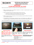
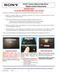
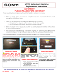
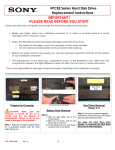
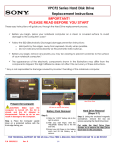
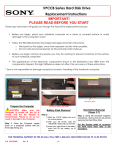
VPCSB Series Optical Disk Drive Replacement Instructions IMPORTANT! PLEASE READ BEFORE YOU START These easy instructions will guide you through the Hard Drive replacement process. Before you begin, place your notebook computer on a clean or covered surface to avoid damage to the computer's case.* Follow the ESD (Electrostatic Discharge) damage prevention instructions: o o Hold parts by the edges, away from exposed circuitry when possible. Do not walk around excessively as this promotes static build-up. Before you begin, remove any jewelry you may be wearing to prevent scratches to the surface of your notebook computer.* The appearance of the electronic components shown in the illustrations may differ from the components shipped. This slight difference does not affect the accuracy of these instructions. * Sony is not responsible for damage caused by incorrect handling of the notebook computer. Prepare the Computer CAUTION: Make sure the Computer is turned off, the lid is closed, and the AC Adapter is disconnected. Failure to do so can result in damage to the Computer. Place the Computer upside down on a protected surface with the front edge facing you. Battery Pack Removal NOTE: If your unit is configured with an Extended Battery Pack, it must be removed before beginning this procedure. Extended Battery Pack Removal Step 1. Using the enclosed magnetic screwdriver, remove the two (2) screws securing the Battery Door. Put the screws aside to re-secure the Door later in the procedure. 1) Slide the “LOCK” battery tab up to the unlock position. 2) Slide the “RELEASE” battery tab to the right and hold. 3) Rotate the battery up to remove. FOR TECHNICAL SUPPORT IN THE US CALL TOLL FREE 1-866-651-7669 FROM 9:00 AM TO 11:00 PM EST P/N 989202618 Rev. B 1/4 VPCSB Series Optical Disk Drive Replacement Instructions Step 2. Slide the Battery Door towards the Bottom edge of the unit to remove. ODD Removal Step 1. Using the enclosed magnetic screwdriver, remove the two (2) screws securing the ODD Assembly. Step 3: The Battery Pack is located as shown. Step 4. Locate the Battery Lock. Slide down to the “UNLOCK” position and hold. Grasp the Battery from the Left side and lift up to remove. Step 2. Insert your fingers in the space between the ODD and the unit. Gently slide the ODD away from the unit. Step 3. Carefully remove the ODD Assembly from the unit. Put the screws aside to re-secure the ODD later in the procedure. ODD Disassembly Step 2. Remove the screws & brackets. Step 1. Identify the four (4) screws which secure the ODD Brackets to the ODD. Put the ODD Brackets and screws aside for transfer to the new ODD. Step 3. Arrange the Brackets & screws as shown above and then set the old ODD aside. FOR TECHNICAL SUPPORT IN THE US CALL TOLL FREE 1-866-651-7669 FROM 9:00 AM TO 11:00 PM EST P/N 989202618 Rev. B 2/4 VPCSB Series Optical Disk Drive Replacement Instructions ODD Assembly NOTE: Identify tabs on the Bezel and tab holes located on the ODD. Step 2. Align the tabs on the Bezel with the tab holes located on the ODD. Carefully press the Bezel into place. Step 4. Using the ODD Screws, install the Brackets onto the new ODD. NOTE: After installation, all brackets should sit flush with the ODD. The stamped letters located on the brackets should all be facing the same direction. Step 1. Take the new ODD and Bezel provided in the CRU kit and prepare for assembly. Old Hard Drive DriveDrive Step 3. Position the new ODD (Label side down) and identify the correct Bracket with the corresponding ODD side (as shown). Take note of the different shapes for each Bracket and the proper alignment of the screw holes. FOR TECHNICAL SUPPORT IN THE US CALL TOLL FREE 1-866-651-7669 FROM 9:00 AM TO 11:00 PM EST P/N 989202618 Rev. B 3/4 VPCSB Series Optical Disk Drive Replacement Instructions ODD Installation Step 1. Align the ODD assembly properly (label side down) and slide into the computer. Step 2. Make sure the new ODD is seated flush on the edge of the Computer. Step 3. Reinstall the two (2) ODD Bay screws to secure. Step 2. Re-attach the Hard Drive/Battery Door by sliding up towards the unit. Verify the Door sits completely flush. Step 3. Re-install the two (2) Hard Drive Door screws to secure the Door. Battery Reinstallation Step 1. Reinstall the Battery into the Battery Bay. Step 4. Reconnect the AC Adaptor. Return the old Optical Drive to Sony using the included shipping instructions. FOR TECHNICAL SUPPORT IN THE US CALL TOLL FREE 1-866-651-7669 FROM 9:00 AM TO 11:00 PM EST P/N 989202618 Rev. B 4/4