1
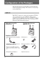
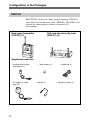
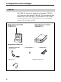
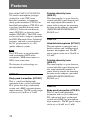
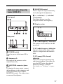
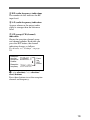
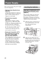
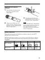
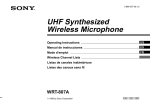
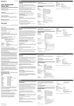
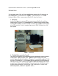
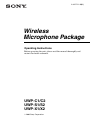
2-347-711-32(2) Wireless Microphone Package Operating Instructions Before operating the unit, please read this manual thoroughly and retain it for future reference. UWP-C1/C2 UWP-S1/S2 UWP-X1/X2 2003 Sony Corporation 2 Table of Contents Configuration of the Packages ............................. 4 UWP-C1 ..................................... 4 UWP-C2 ..................................... 5 UWP-S1 ..................................... 6 UWP-S2 ..................................... 7 UWP-X1 .................................... 8 UWP-X2 .................................... 9 Features .................................. 10 Precautions ............................. 12 Parts Identification ................. 13 Body-pack transmitter (UTX-B1) ................................. 13 Hand-held microphone (UTX-H1) ................................ 14 Portable diversity tuner (URX-P1) ................................. 15 Half-rack size diversity tuner (URX-R1) ................................ 17 Diversity tuner module (URX-M1) ............................... 18 Power Supply ......................... 20 Inserting the batteries ............... 20 Attachment and Installation Procedures ........................ 23 Attaching the supplied accessories to the body-pack transmitter (UTX-B1) .............. 23 Attaching the supplied accessory to the hand-held microphone (UTX-H1) ................................ 24 Attaching the supplied accessories to the portable diversity tuner (URX-P1) ................................. 24 Installing the diversity tuner module (URX-M1) .................. 25 Settings ................................... 28 Setting the transmission channel ..................................... 28 Setting the reception channel ... 29 Detecting and selecting the available channels automatically (diversity tuner module (URX-M1) only) ......... 30 Setting the attenuation level of the audio input ..................... 31 Resetting the accumulated battery use time indication ....... 32 Setting the RF output level ...... 32 Setting the monitor level (portable diversity tuner (URX-P1) only) ....................... 33 Operation ................................ 34 System Configurations .......... 35 Error Messages ...................... 38 Troubleshooting ..................... 39 Specifications ......................... 41 Appendix ................................. 45 Wireless microphone system frequency list ............................ 45 AC adapter for use with the URX-R1 ................................... 47 3 Configuration of the Packages Configuration of the Packages This operation manual is for the UWP-C1/C2/S1/S2/X1/X2 wireless microphone packages. The contents of each package are described below. UWP-C1 The UWP-C1 consists of a body-pack transmitter (UTX-B1) and a portable diversity tuner (URX-P1). When used in conjunction with a compact camcorder, the UWP-C1 makes a mobile system for ENG (Electronic News Gathering) or EFP (Electronic Field Production) purposes. Body-pack transmitter (UTX-B1) (1) Portable diversity tuner (URX-P1) (1) Supplied accessories • Omni-directional lavalier microphone (1) • Wind screen (1) • XLR-BMP conversion cable (for use with the URX-P1 only) (1) • Shoe mount adapter (1) • Belt clip (2) • Stereo mini plug-BMP conversion cable (for use with the URX-P1 only) (1) • Microphone stand adapter (1) 4 • Operation manual (1) • Holder clip (1) UWP-C2 The UWP-C2 consists of a hand-held microphone (UTX-H1) and a portable diversity tuner (URX-P1). When used in conjunction with a compact camcorder, the UWP-C2 makes a mobile system for ENG (Electronic News Gathering) or EFP (Electronic Field Production) purposes. Hand-held microphone (UTX-H1) (1) Portable diversity tuner (URX-P1) (1) Supplied accessories • Microphone holder (1) • Belt clip (1) • Shoe mount adapter (1) • XLR-BMP conversion cable (for use with the URX-P1 only) (1) • Stereo mini plug-BMP conversion cable (for use with the URX-P1 only) (1) • Microphone stand adapter (1) • Operation manual (1) 5 Configuration of the Packages UWP-S1 The UWP-S1 consists of a body-pack transmitter (UTX-B1) and a half-rack size diversity tuner (URX-R1). The UWP-S1 is suitable for constructing a wireless system for AV presentations. Half-rack size diversity tuner (URX-R1) (1) Body-pack transmitter (UTX-B1) (1) Supplied accessories • Unidirectional lavalier microphone (1) • AC adapter (1) (See page 47.) 6 • Wind screen (1) • Belt clip (1) • Holder clip (1) • Operation manual (1) UWP-S2 The UWP-S2 consists of a hand-held microphone (UTX-H1) and a half-rack size diversity tuner (URX-R1). The UWP-S2 is suitable for constructing a wireless system for AV presentations. Hand-held microphone (UTX-H1) (1) Half-rack size diversity tuner (URX-R1) (1) Supplied accessories • Microphone holder (1) • AC adapter (1) (See page 47.) • Operation manual (1) 7 Configuration of the Packages UWP-X1 The UWP-X1 consists of a body-pack transmitter (UTX-B1) and a diversity tuner module (URX-M1). By installing the tuner module into a tuner base unit or a powered mixer, the system construction to meet the desired purpose of use and required system scale becomes possible. Body-pack transmitter (UTX-B1) (1) Diversity tuner module (URX-M1) (1) Supplied accessories • Unidirectional lavalier microphone (1) • Belt clip (1) 8 • Wind screen (1) • Holder clip (1) • Operation manual (1) UWP-X2 The UWP-X2 consists of a hand-held microphone (UTX-H1) and a diversity tuner module (URX-M1) . By installing the tuner module into a tuner base unit or a powered mixer, the system construction to meet the desired purpose of use and required system scale becomes possible. Hand-held microphone (UTX-H1) (1) Diversity tuner module (URX-M1) (1) Supplied accessories • Microphone holder (1) • Operation manual (1) 9 Features Features Each of the UWP-C1/C2/S1/S2/X1/ X2 wireless microphone packages (referred to as the UWP series hereafter) combines a transmitter (body-pack transmitter (UTX-B1) or hand-held microphone (UTX-H1)) and a receiver (portable diversity tuner (URX-P1), half-rack size diversity tuner (URX-R1), or diversity tuner module (URX-M1)). The UWP series can be used with a compact camcorder for ENG (Electronic News Gathering) purposes, and with a powered mixer for AV presentations or as a PA (public address) system. Note The UWP series is not compatible with conventional WRT series transmitters, WRR series tuners, or WRU series tuner units. The features of each package are described below. UWP-C1 Body-pack transmitter (UTX-B1) This is a small and lightweight transmitter with a crystal-controlled PLL (phase lock loop) synthesized system and a BMP-type microphone input connector. The RF power output can be set at 10 mW or at 2 mW. 10 Portable diversity tuner (URX-P1) This tuner employs a space diversity system with little signal dropout and two angle-adjustable antennas. It comes with an adapter for mounting the tuner on the compact camcorder (DSR-PDX10/PDX10P/PD150/ PD150P, etc.). UWP-C2 Hand-held microphone (UTX-H1) This microphone is equipped with a built-in antenna and a unidirectional dynamic microphone unit. The RF power output can be set at 10 mW or at 2 mW. Portable diversity tuner (URX-P1) This tuner employs a space diversity system with little signal dropout and two angle-adjustable antennas. It comes with an adapter for mounting the tuner on the compact camcorder (DSR-PDX10/PDX10P/PD150/ PD150P, etc.). UWP-S1 Body-pack transmitter (UTX-B1) This is a small and lightweight transmitter with a crystal-controlled PLL (phase lock loop) synthesized system and a BMP-type microphone input connector. The RF power output can be set at 10 mW or at 2 mW. Half-rack size diversity tuner (URX-R1) This tuner employs a space diversity system with little signal dropout and two angle-adjustable antennas. It comes with two types of audio connectors (1/4-inch jack and XLR type) on the rear panel. UWP-S2 Hand-held microphone (UTX-H1) This microphone is equipped with a built-in antenna and a unidirectional dynamic microphone unit. The RF power output can be set at 10 mW or at 2 mW. UWP-X2 Hand-held microphone (UTX-H1) This microphone is equipped with a built-in antenna and a unidirectional dynamic microphone unit. The RF power output can be set at 10 mW or at 2 mW. Diversity tuner module (URX-M1) This tuner module can be incorporated into the MB-806A Tuner Base Unit or SRP-X700P Powered Mixer. Half-rack size diversity tuner (URX-R1) This tuner employs a space diversity system with little signal dropout and two angle-adjustable antennas. It comes with two types of audio connectors (1/4-inch jack and XLR type) on the rear panel. UWP-X1 Body-pack transmitter (UTX-B1) This is a small and lightweight transmitter with a crystal-controlled PLL (phase lock loop) synthesized system and a BMP-type microphone input connector. The RF power output can be set at 10 mW or at 2 mW. Diversity tuner module (URX-M1) This tuner module can be incorporated into the MB-806A Tuner Base Unit or SRP-X700P Powered Mixer. 11 Precautions Precautions • The UWP series product must be used within a temperature range of 0°C to 40°C (32°F to 104°F). • Operating the UWP series product near electrical equipment (motors, transformers, or dimmers) may cause it to be affected by electromagnetic induction. Keep the UWP series product as far from such equipment as possible. • The presence of the lighting equipment may produce electrical interference over the entire frequency range. Position the UWP series product so that interference is minimized. • To avoid degradation of the signalto-noise ratio, do not use the UWP series product in noisy places or in locations subject to vibration, such as the following: — near electrical equipment, such as motors, transformers or dimmers — near air conditioning equipment or places subject to direct air flow from an air conditioner — near public address loudspeakers — where adjacent equipment might knock against the tuner Keep the UWP series product as far from such equipment as possible or use buffering material. • Clean the surface and the connectors of the UWP series product with a dry, soft cloth. Never use thinner, benzene, alcohol or any other chemicals, since these may mar the finish. 12 To prevent electromagnetic interference from portable communication devices The use of portable telephones and other communication devices near the UWP series product may result in malfunction and interference with audio signals. It is recommended that portable communication devices near the UWP series product be turned off. Parts Identification Body-pack transmitter (UTX-B1) A AF (audio frequency) indication Appears whenever the input audio signal is stronger than the reference level. B RF (antenna output) indication Appears during signal transmission from the antenna. C RF (antenna output) level indication Shows the RF output level setting. For details, see “Setting the RF output level” on page 32. D BATT (battery) indication Shows the battery condition. For details, see “Power Supply” on page 20. 1 Antenna 2 Audio input connector Connect the supplied lavalier microphone here. E CH (channel) indication Shows the transmission channel. Each time you press the SET button in transmission mode, the channel indication changes as follows. For details, see “Settings” on page 28. 3 Power indicator Lights up red when the transmitter is tuned on. Transmission channel 4 Display section Transmission frequency A B C D AF RF BATT H L Attenuation level of the input signal Press the SET button. Accumulated battery use time CH E 13 Parts Identification 5 + (+ selection) / – (– selection/ reset) buttons Press these buttons to set the transmission channel, frequency, or attenuation level of the input signal. The “–” button resets the accumulated battery use time to “00:00”. 1 Power indicator Lights up red when the microphone is turned on. 6 Battery compartment Accommodates two LR6 (size AA) alkaline batteries. For details on how to insert the batteries, see “Power Supply” on page 20. 3 Battery compartment Accommodates two LR6 (size AA) alkaline batteries. For details on how to insert the batteries, see “Power Supply” on page 20. 7 SET button Press to change and enter display parameters. For details, see “Settings” on page 28. 4 Display section 8 POWER switch Turns the power of the transmitter ON or OFF. Hand-held microphone (UTX-H1) The rear side of the battery compartment 14 2 POWER switch Turns the power of the microphone ON or OFF. A B C D H L E A AF (audio frequency) indication Appears whenever the input audio signal is stronger than the reference level. B RF (antenna output) indication Appears during signal transmission from the antenna. C RF (antenna output) level indication Shows the RF output level setting. For details, see “Setting the RF output level” on page 32. D BATT (battery) indication Shows the battery condition. For details, see “Power Supply” on page 20. Portable diversity tuner (URX-P1) E CH (channel) indication Shows the transmission channel. Each time you press the SET button, the channel indication changes as follows. For details, see “Settings” on page 28. Transmission channel Transmission frequency Attenuation level of the input signal Press the SET button. Accumulated battery use time 5 + (+ selection) / – (– selection/ reset) buttons Press these buttons to set the transmission channel, frequency, or attenuation level of the input signal. The “–” button resets the accumulated battery use time to “00:00”. 6 SET button Press to change display parameters. For details, see “Settings” on page 28. 1 Antennas a/b The angle of the antennas can be adjusted manually. 2 MONITOR connector (3.5-mm diameter stereo mini jack) To monitor the tuner output, connect the headphones to this connector. 3 RF (radio frequency) indicator Indicates the strength of the RF input signal. On in green: RF input is 15 dBµ* or more. Off: RF input is less than 15 dBµ*. ...................................................................................................................................................................... * 0 dBµ = 1 µVEMF 15 Parts Identification 4 Display section C A B RF 5 + (+ selection) / – (– selection/ reset) buttons Press these buttons to set the reception channel and frequency. The “–” button resets the accumulated battery use time to “00:00”. These buttons can also be used to adjust the monitor level. BATT AF CH D A RF (radio frequency) indications The number of dots indicates the RF input level. B AF (audio frequency) indication Appears whenever the output audio signal is stronger than the reference level. C BATT (battery) indication Shows the battery condition. For details, see “Power Supply” on page 20. D GP (group)/CH (channel) indication Shows the reception channel group and channel number. Each time you press the SET button, the channel indication changes as follows. For details, see “Settings” on page 28. Reception channel group and number Reception frequency Accumulated battery use time 16 Press the SET button. 6 Battery compartment Accommodates two LR6 (size AA) alkaline batteries. For details on how to insert the batteries, see “Power Supply” on page 20. 7 SET button Press to change display parameters. For details, see “Settings” on page 28. 8 POWER switch Turns the power of the tuner ON or OFF. 9 OUTPUT (audio output) connector (3.5-mm diameter stereo mini jack) Connect one end of the supplied XLRBMP conversion cable or the stereo mini plug-BMP conversion cable here and the other end to the microphone input on a camcorder, mixer, or amplifier. If the microphone input connector on the device connected to the tuner is a stereo mini jack, connect the straight (BMP) plug (2-pole) to the tuner and the L-shaped (stereo mini) plug (3-pole) to the microphone input connector on the device. Half-rack size diversity tuner (URX-R1) Front panel 4 MONITOR control Turn to adjust the output monitoring level (through the headphones). 5 + (+ selection) / – (– selection/ reset) buttons Press these buttons to set the reception channel and frequency. 6 Display section A B RF Rear panel AF CH C A RF (radio frequency) indications The number of dots indicates the RF input level. 1 POWER switch Turns the power of the tuner ON or OFF. 2 Antennas a/b The angle of the antennas can be adjusted manually. 3 MONITOR connector (phone jack) To monitor the tuner output, connect the headphones to this connector and adjust the monitor level with the MONITOR control. Use either stereo or monaural headphones. B AF (audio frequency) indication Appears whenever the output audio signal is stronger than the reference level. C GP (group)/CH (channel) indication Shows the reception channel group and channel number. Each time you press the SET button, the channel indication changes as follows. For details, see “Settings” on page 28. 17 Parts Identification Reception channel group and number Reception frequency Press the SET button. qs DC IN 9V (DC power input) connector Connect the supplied AC adapter here. Diversity tuner module (URX-M1) 7 RF (radio frequency) indicator Indicates the strength of the RF input signal. On in green: RF input is 25 dBµ* or more. Off: RF input is less than 25 dBµ*. 8 SET button Press to change display parameters. For details, see “Settings” on page 28. 9 TUNER OUTPUT (audio output) connector (XLR type) Connect to the audio input connector of a mixer or amplifier, etc. 0 LEVEL (audio output level) switch Sets the output level of the TUNER OUTPUT connector (XLR type) to –28 dBm or –58 dBm. Select the setting according to the input level of the equipment connected to the tuner. 1 SET button Press to change display parameters. For details, see “Settings” on page 28. 2 RF (radio frequency) indicator Indicates the strength of the RF input signal. On in green: RF input is 25 dBµ* or more. Off: RF input is less than 25 dBµ*. 3 Display section A B RF qa TRS PHONE (tuner audio output) connector (1/4-inch jack) Connect to the audio input connector of a mixer or amplifier, etc. The output level from this connector is –30 dBm. AF CH C ...................................................................................................................................................................... * 0 dBµ = 1 µVEMF 18 A RF (radio frequency) indications The number of dots indicates the RF input level. B AF (audio frequency) indication Appears whenever the output audio signal is stronger than the reference level. C GP (group)/CH (channel) indication Shows the reception channel group and channel number. Each time you press the SET button, the channel indication changes as follows. For details, see “Settings” on page 28. Reception channel group and number Reception frequency Press the SET button. 4 + (+ selection) / – (– selection/ reset) buttons Press these buttons to set the reception channel and frequency. 19 Power Supply Power Supply This section explains the power supply for each component. • Half-rack size diversity tuner (URX-R1) Connect the supplied AC adapter to the DC IN 9V connector on the rear panel, and then connect the AC adapter to a wall outlet. • Diversity tuner module (URX-M1) When incorporated into another component (e.g., MB-806A, SRPX700P, etc.), the tuner module draws its power from that component. For details on the power supply to the diversity tuner module, refer to the operating instructions of the component in which the diversity tuner module is installed. Inserting the batteries Body-pack transmitter (UTXB1)/portable diversity tuner (URX-P1) The procedure below uses the bodypack transmitter (UTX-B1) in the illustrations. Batteries are, however, inserted in the portable diversity tuner (URX-P1) in the same manner. 1 Slide the latches on both sides of the transmitter/tuner at the same time and open the battery compartment. Latch • Body-pack transmitter (UTXB1), hand-held microphone (UTX-H1), and portable diversity tuner (URX-P1) These components can be powered by two LR6 (size AA) alkaline batteries for about six hours of continuous operation (at 25 ºC (77ºF)). Details on inserting the batteries and the battery condition indication are given below: 20 2 Align two new LR6 (size AA) alkaline batteries with the polarity markings and insert them into the battery compartment, and then close the cover. Hand-held microphone (UTX-H1) 1 Turn the grip in the direction of the arrow to open the battery compartment. 3 2 Turn the grip in the direction opposite to the arrow in step 1 to close the battery compartment. Note Align two new LR6 (size AA) alkaline batteries with the polarity markings and insert them into the battery compartment. If you open the battery compartment during signal transmission, the noise may occur. Be sure to turn the microphone off before opening the battery compartment. Battery indication When you turn the power on, the battery condition is shown by the BATT indication in the display section. When the indication in column 4 starts to flash, replace the batteries with new ones. Be sure to check the expiration date printed on the new batteries before using them. 1 2 3 4 BATT indication Lights Lights Lights Flashes Battery status Good Less than 50% charged Less than 20% charged Almost drained 21 Power Supply Note The indicated battery condition may not be correct if the batteries were not new when installed. If you plan to use the component for a long period, it is recommended that you replace the batteries with brand new ones. Notes on batteries Batteries may leak or explode if mistreated. Be sure to follow these instructions. • Be sure to install the batteries with the correct polarity. • Always replace the two batteries together. • Do not use different types of batteries or old and new one together. • The batteries are not rechargeable. • When not using the component for a long period of time, remove the batteries to avoid leakage. If the batteries do leak, clean all leakage from the battery compartment and the component. Leakage left in the compartment and the component may cause poor battery contact. If there seems to be poor battery contact, consult your Sony dealer. 22 Attachment and Installation Procedures This section describes the procedures for attaching the supplied accessories to components and the installation of the diversity tuner module (URX-M1) into the MB-806A Tuner Base Unit or SRP-X700P Powered Mixer. Attaching the supplied accessories to the body-pack transmitter (UTX-B1) Attaching the wind screen to the microphone Insert the microphone into the hole at the bottom of the windscreen. Attaching the belt clip Attaching the microphone Microphone (supplied) For a secure connection, be sure to turn and lock the connector cover. Attaching the holder clip to the microphone Insert one end of the belt clip into one of two holes on either side of the transmitter, and then insert the other end into the hole on the other side. Push the holder clip against the bottom of the microphone until the holder clip clicks into place. 23 Attachment and Installation Procedures Removing the belt clip Insert a pointed object such as a ballpoint pen between the belt clip and the transmitter to make some space between them, and then remove the end of the belt clip from the hole on the side of the transmitter. Attaching the supplied accessories to the portable diversity tuner (URX-P1) Connecting the supplied conversion cable to the OUTPUT connector Example: XLR-BMP conversion cable (supplied) Attaching the supplied accessory to the handheld microphone (UTX-H1) Attaching the microphone holder For a secure connection, be sure to turn and lock the connector cover. Note The supplied conversion cables are for use with the URX-P1 only. Attaching the cable to the audio input connector of the UTX-B1 may cause damage to the transmitter or the device connected to the transmitter. Attaching the belt clip See “Attaching the belt clip” on page 23. Insert the bottom part of the microphone into the holder. 24 Attaching the shoe mount adapter Attaching the microphone stand adapter After attaching the belt clip and the shoe mount adapter, insert the microphone stand adapter into the screw hole at the top of the shoe mount adapter, and then rotate the microphone stand adapter until it is securely attached. Be sure to hold the horizontal part of the belt clip with the horizontal groove on the shoe mount adapter. After attaching the belt clip, insert the shoe mount adapter between the portable diversity tuner (URX-P1) and the belt clip, with the vertical parts of the belt clip aligned with the two vertical parallel grooves on the shoe mount adapter. Then, push the shoe mount adapter in the direction of the arrow, and then catch the horizontal part of the belt clip with the horizontal groove on the shoe mount adapter to hold the belt clip in place. Installing the diversity tuner module (URX-M1) Notes • Before installing the diversity tuner module (URX-M1), make sure the unit into which the diversity tuner module (URX-M1) will be installed is turned off. Do not install or uninstall the diversity tuner module (URX-M1) while the unit is turned on, as this may damage the connector or cause noise. 25 Attachment and Installation Procedures • The buttons and display on the front panel of the diversity tuner module (URX-M1) may be damaged if they are gripped too strongly. Always hold the diversity tuner module by the side. • Do not put your fingers on the connectors on the rear panel of the diversity tuner module (URX-M1) or into the slot on the unit into which the diversity tuner module (URXM1) will be installed. • Keep the diversity tuner module (URX-M1) away from static electricity. 2 Installing a diversity tuner module (URX-M1) into an MB806A Tuner Base Unit Removing a diversity tuner module (URX-M1) On the bottom panel of the MB-806A, locate the lever corresponding to the slot of the diversity tuner module (URX-M1) to be removed and pull the lever forward. The diversity tuner module (URX-M1) is ejected from the slot. The MB-806A Tuner Base Unit can accommodate up to 6 diversity tuner modules (URX-M1). 1 Holding both sides of the diversity tuner module (URX-M1), insert it into the slot. Push it in until you hear a click. 26 To install two or more diversity tuner modules (URX-M1) , detach the necessary number of blank panels by pressing the top and bottom tabs on each panel towards each other and pulling the panel out. Then do step 1 for each module. Lever Installing a diversity tuner module (URX-M1) into an SRP-X700P Powered Mixer SCENE RECALL MASTER A B ECT LINE 4 SEL A B C The SRP-X700P Powered Mixer can accommodate up to 2 diversity tuner modules (URX-M1). 1 D E AF GP F BATT RF GP CH Diversity tuner module (URX-M1) Remove the tuner slot cover from the SRP-X700P and inspect the top and bottom sides of the diversity tuner module. Then, holding the tuner module on both sides, insert it into the slot. Diversity tuner module (URX-M1) SCENE RECALL MASTER A B ECT LINE 4 SEL A B C D E AF F GP BATT RF GP CH Removing the diversity tuner module (URX-M1) Insert a screwdriver with a shaft diameter of between 2 to 4 mm and a shaft length of 30 mm or longer into the hole under the lower part of the tuner slot and remove the tuner module. 27 Settings Settings Setting the transmission channel The procedure below is the same for all UWP series transmitters (UTX-B1/H1). See “Wireless microphone system frequency list” on page 45 for details on the selectable channel groups and channels. 1 Turn on the transmitter while pressing down the SET button. Keep pressing the SET button until the display section parameters that were displayed when the unit was last turned off start to flash. 2 Press the SET button repeatedly until the channel number (or frequency) indication appears. 3 Press the + or – button to select the channel number (or frequency). Pressing the + button cycles the indication in the order shown in the tables in “Wireless microphone system frequency list” on page 45. Pressing the – button cycles the indications in the opposite direction. Hold down the + or – button to change the channel number (or frequency) faster. 28 4 When the desired channel number (or frequency) appears, set the POWER switch to OFF to complete the setting, or press the SET button to set other items. The results are stored in memory. The stored channel number (or frequency) will appear in the display section the next time you turn on the transmitter by setting the POWER switch to ON. Notes • When you are setting the transmission channel, the transmitter cannot be used to transmit signals. • Do not remove the batteries while setting the transmission channel. If they are inadvertently removed, reinsert them immediately and redo the procedure “Setting the transmission channel” from step 1. • Make sure that the selected channel is the same on the transmitter and tuner being used in the same system. • If you turn off the transmitter and then immediately turn it on right after setting the transmission channel, the unit may not operate normally. Wait a few seconds before turning it on again. Hold down the + or – button to change the channel group faster. Setting the reception channel The procedure below is the same for all UWP series tuners (URX-P1/R1/M1). 4 The selected group is entered. The right four digits start to flash to allow the selection of the channel number. See “Wireless microphone system frequency list” on page 45 for details on the selectable channel groups and channels. 1 Press down the SET button for more than one second. Keep pressing the SET button until the display section parameters start to flash. 2 5 Press the + or – button to select the channel number. The channel indication changes in the order shown in the tables in “Wireless microphone system frequency list” on page 45. Press the SET button repeatedly until the channel group and the channel number indications appear. The channel group indication starts to flash. 3 When the desired channel group number appears, press the SET button. Example: When the channel group 00 is selected Press the + or – button to select the channel group. Pressing the + button cycles the indication in the order shown in the tables in “Wireless microphone system frequency list” on page 45. Pressing the – button cycles the indications in the opposite direction. 6 When the desired channel number appears, leave the tuner for about 10 seconds until the selected channel number stops flashing and the selection is stored in memory. 29 Settings To selct the channel by frequency indication 1 Press the SET button for more than one second. Keep pressing the SET button until the display seciton parameters start to flash. 2 Press the SET button repeatedly until the frequency indication appears and starts flashing. 3 Press the + or – button to select the frequency. 4 When the desired frequency appears, leave the tuner for about 10 seconds until the selected channel frequency stops flashing and the selection is stored in memory. Notes • When you are setting the reception channel, the tuner can be used to receive signals. • Do not remove the batteries while setting the reception channel. If they are inadvertently removed, re-insert them immediately and redo the procedure “Setting the reception channel” from step 1. • Make sure that the selected channel is the same on the transmitter and tuner being used in the same system. 30 • If you turn off the tuner and then immediately turn it on right after setting the reception channel, the unit may not operate normally. Wait a few seconds before turning it on again. Detecting and selecting the available channels automatically (diversity tuner module (URX-M1) only) When multiple diversity tuner modules (URX-M1) are installed into the MB-806 to perform simultaneous multiple-channel operation, select the channel group on the tuner module installed into the slot 1 of the MB806, then all the tuner mudules installed into the MB-806 can be set to different channels within the selected channel group. 1 Turn off all the microphones and transmitters. 2 Select the channel group on the tuner module installed into the slot 1 of the MB-806. 3 After confirming that the channel group indication has stopped flashing (about 10 seconds after you have selected the channel group), keep pressing the + button on the tuner module installed into the slot 1 of the MB-806. All the tuner modules installed into the MB-806 are set to the available channels within the selected channel group. After the automatic detection and selection of available channels finish, you can change the group and channel on each tuner module manually. 1 Do the following while there is no signal transmission. Turn on the transmitter while pressing down the SET button, and press the SET button repeatedly until the attenuation level indication appears in the display section. Notes • Do the automatic detection and selection of available channels with the channel group other than channel group 00. • When there are unavailable channels due to extraneous radio wave and the channel could not be selected on some tuner modules, “NO CH” appears on the display of those tuner modules. If this happens, select the channel group with no interference from extraneous radio wave, and repeat the procedure above. Setting the attenuation level of the audio input The procedure below is the same for all UWP series transmitters (UTX-B1/H1). The attenuation level can be set during signal transmission. Do the following while there is signal transmission. Press the SET button repeatedly until the attenuation level indication appears in the display section. 2 Press the + or – button to select the attenuation level. The selectable range is from 0 dB to 21 dB in steps of 3 dB (the factory setting is 0 dB). 3 Do the following while there is no signal transmission. Set the POWER switch to OFF to complete the setting, or press the SET button to set other items. The results are stored in memory. The change becomes effective the next time you turn on the transmitter by setting the POWER switch to ON. 31 Settings Resetting the accumulated battery use time indication The procedure below is the same for all UWP series transmitters (UTX-B1/H1) and the portable diversity tuner (URX-P1). The accumulated battery use time is the total time (in hours and minutes) that the batteries have been used. It is recorded whenever the transmitter/ microphone/tuner is on. Reset the indication to “00:00” whenever you replace the batteries. 1-a For transmitters (UTX-B1/H1) 3 The time indication resets to “00:00.” While “00:00” is still displayed, you can return to previous value by pressing the + button. 4-a For transmitters (UTX-B1/H1) Set the POWER switch to OFF to complete the setting, or press the SET button to set other items. The results are stored in memory. The change becomes effective the next time you turn on the unit by setting the POWER switch to ON. 4-b For the portable diversity tuner (URX-P1) Leave the tuner for about 10 seconds until the time indication stops flashing and the setting is stored in memory. Turn on the unit while pressing down the SET button. 1-b For the portable diversity tuner (URX-P1) Press down the SET button for more than one second. Keep pressing the SET button until the display section parameters start to flash. 2 Press the SET button repeatedly until the accumulated time indication appears in the display section. Setting the RF output level The procedure below is the same for all UWP series transmitters (UTX-B1/H1). You can select an RF output level of H (10 mW) or L (2 mW) in setting mode. Set the RF output level to L (2 mW) for simultaneous operation of multiple channels, and set it to H (10 mW) for long-distance operation. 1 32 Press the – button. Turn on the transmitter while pressing down the SET button. 2 Press the SET button repeatedly until the RF output level indication appears in the display section. 3 Press the + button to select H (10 mW), or press the – button to select L (2 mW). 4 Set the POWER switch to OFF to complete the setting, or press the SET button to set other items. 2 Press the + button to increase the monitor level, or press the – button to decrease the level. When you leave the tuner for about two seconds or more, current monitor level setting is stored in memory and the normal display resumes. Note that monitor level setting is effective after you turn off the tuner, then turn it on again. The results are stored in memory. The change becomes effective the next time you turn on the transmitter by setting the POWER switch to ON. Setting the monitor level (portable diversity tuner (URX-P1) only) You can set the monitor level for monitoring the tuner output within the range of 01 to 24. 1 While the parameters on the display section are not flashing, press the + or – button once. The monitor level indication appears in the display section. 33 Operation Operation The procedure below is the same for all UWP series components (UTX-B1/H1 and URX-P1/R1/M1). 1 Make all necessary connections on the tuner. For examples of UWP series component connections, see “System Configurations” on page 35. 2 Set the transmission channel on the transmitter, and then turn off the unit. For details on setting the transmission channel, see “Setting the transmission channel” on page 28. 3 Turn on the tuner. The parameters that were in the display section when the tuner was last turned off appear again. Note Before turning on the tuner, turn down the volume of the equipment connected to the tuner. Otherwise, noise will be produced when the tuner is turned on. 4 Set the reception channel on the tuner. For details on setting the reception channel, see “Setting the reception channel” on page 29. 5 34 Turn on the transmitter. If noise is heard Depending on the environment where the UWP series components are installed, external noise or radio waves may disrupt transmission on certain channels. When selecting a channel under these circumstances, turn off the transmitter. Then, on the tuner, select a channel for which the RF indications do not appear in the display section or for which the RF indicator does not light up (i.e., a channel free from noise or radio wave interference). Set the same channel on the transmitter. Note To prevent interference or noise, please take the following precautions. • Do not use two or more transmitters with the same wireless channels. • When operating two or more UWP series simultaneously, set each series to a different channel within the same channel group. • Keep the reception antenna and the transmitter separated more than 3 meters (9 feet 11 inches). • When operating two or more UWP series simultaneously with the same channel group, make sure that they are at least 100 meters (330 feet) apart, but within clear sight of each other. (The actual distance may differ depending on the circumstances.) System Configurations The UWP series is used in the following configuration examples. Sample configurations for ENG (Electronic News Gathering) or EFP (Electronic Field Production) with a digital camcorder Portable diversity tuner (URX-P1) (with the shoe mount adapter attached) DSR-PDX10/PDX10P/PD150/PD150P DVCAM Digital Camcorder Body-pack transmitter (UTX-B1) or Portable diversity tuner (URX-P1) (with the shoe mount adapter attached) Hand-held microphone (UTX-H1) DSR-PDX10/PDX10P/PD150/PD150P DVCAM Digital Camcorder 1 XLR-BMP conversion cable (supplied) 2 Lavalier microphone (supplied) 35 System Configurations Sample configurations for AV presentations Portable diversity tuner (URX-P1) (with the shoe mount adapter attached) Hand-held microphone (UTX-H1) Body-pack transmitter (UTX-B1) To DVD player, PC, or VTR, etc. SRP-X700P Powered Mixer or Hand-held microphone (UTX-H1) Half-rack size diversity tuner (URX-R1) To DVD player, PC, or VTR, etc. SRP-X700P Powered Mixer AN-820 UHF antenna Diversity tuner module (URX-M1) Body-pack transmitter (UTX-B1) 1 XLR cable with the XLR-BMP conversion cable (supplied) 2 Lavalier microphone (supplied) 3 BNC cable 4 XLR cable or pin cable 36 Sample configuration of a PA system Hand-held microphone (UTX-H1) AN-820 UHF antenna Diversity tuner module (URX-M1) Body-pack transmitter (UTX-B1) To DVD player, PC, or VTR, etc. SRP-X700P Powered Mixer 1 Lavalier microphone (supplied) 2 BNC cable 3 XLR cable 4 XLR cable or pin cable Diversity tuner module (URX-M1) *1 WD-820A Antenna Divider *2 MB-806A Tuner Base Unit *3 SRP-X100 Audio Mixer 37 Error Messages Error Messages When a problem occurs, one of the following error messages may appear on the display. Messages Meanings Remedy Err 01 An error has occurred in the backup memory data. Contact your Sony dealer. Err 02 The PLL synthesized circuit is abnormal. Restart the unit. If the message appears again, contact your Sony dealer. Err 03* The battery voltage exceeds the allowable limit. Use the specified batteries. * 38 Body-pack transmitter (UTX-B1)/hand-held microphone (UTX-H1)/portable diversity tuner (URX-P1) only. Troubleshooting If you have any problem using the UWP system, use the following checklist. Should any problem persist, consult your Sony dealer. Symptom Meanings/Remedy The unit does not turn on*. The polarity orientation of the batteries in the battery compartment is incorrect. b Insert the batteries with the correct polarity orientation. The batteries are exhausted. b Replace the batteries with new ones. The battery terminals in the transmitter are dirty. b Clean the + and – terminals with a cotton swab. The batteries become drained quickly*. The batteries are exhausted. b Replace the batteries with new ones. Manganese batteries are being used. b Use alkaline batteries. The battery life of a manganese battery is less than half that of an alkaline battery. The UWP series is being used under cold conditions. b The batteries drain quickly under cold conditions. The channel cannot be changed. An attempt was made to change the channel by pressing the SET button only. b Restart the unit while holding down the SET button. Then change the channel with the + and – buttons. There is no sound. The channel setting on the transmitter is different from that on the tuner. b Use the same channel setting on both the transmitter and tuner. The RF indications (RF indicator) on the tuner do not appear at all (or does not turn on). b Confirm that the transmitter is turned on. The sound is weak. The attenuation level on the transmitter is too high. b The output level of the transmitter is low. Press the + button on the transmitter in attenuation level setting mode to decrease the attenuation level. The volume on the amplifier or mixer is low. b Adjust the volume. * Body-pack transmitter (UTX-B1)/hand-held microphone (UTX-H1)/portable diversity tuner (URX-P1) only. 39 Troubleshooting Symptom Meanings/Remedy There is distortion in the sound. The attenuation level of the transmitter is too low. b The input level of the tuner is extremely high. Press the – button on the transmitter in attenuation level setting mode to raise the attenuation level. The transmitter and the tuner are set to different channels. b Set the transmitter to the same channel. There is sound interruption or noise. The RF indications on the tuner appear (the RF indicator lights up) even when the transmitter is off. b Jamming radio waves are being received. Determine which channels are usable (i.e., channels for which the RF indications on the tuner do not appear (or for which the RF indicator on the tuner does not light up) and set the tuner and transmitter to the same usable channel. When two or more transmitters are used simultaneously, use another channel group that is unaffected by jamming radio waves. The transmitter and the tuner are set to different channels. b Set the transmitter to the same channel. Two or more transmitters are set to the same channel. b Set each transmitter to a different channel. The transmitters are not set to the channels within the same channel group. b The channel plan which the UWP series components use is set so that no signal interference occurs when 2 or more transmitters are used simultaneously. Set each transmitter to a different channel within the same channel group. 40 Specifications Transmitters (UTX-B1/ H1) Items common to all transmitters Oscillator type Crystal-controlled PLL synthesizer Carrier frequencies 794 to 806 MHz Operating frequency band 12 MHz RF output level 10 mW/2 mW selectable Pre-emphasis 50 µs Reference deviation ±5 kHz Frequency characteristics 50 Hz to 18 kHz Distortion 1.0% or less Signal-to-noise ratio 60 dB or more Tone signal 32 kHz Attenuation 0 to 21 dB, in 3-dB steps Display Channel, frequency, audio level, RF level, accumulated battery use time Indicator Power on Power requirements 3.0 V DC (two LR6/AAsize alkaline batteries) Battery life Approx. 6 hours Body-pack transmitter (UTX-B1) Antenna 1/4λ (wave length) wire Audio input connector 3.5-mm dia. mini jack Audio input level –60 dBV to –39 dBV Dimensions Mass 63 × 100 × 27 mm (2 1/2 × 4 × 1 1/8 inches) (w/h/d) (excluding the antennas) Approx. 140 g (5 oz) including batteries 41 Specifications Hand-held microphone (UTX-H1) Microphone unit Dynamic Directivity Unidirectional Antenna 1/4λ (wave length) wire (internal) Dimensions Mass φ 52 × 240 mm (2 1/8 × 9 1/2 inches) (dia/length) Approx. 300 g (11 oz) including batteries Tuners (URX-P1/R1/M1) Items common to all tuners Type of reception Space diversity Oscillator type Crystal-controlled PLL synthesizer Reception frequencies 794 to 806 MHz Operating frequency band 12 MHz Signal-to-noise ratio 60 dB or more De-emphasis 50 µs Reference deviation ±5 kHz Frequency characteristics 50 Hz to 18 kHz Distortion 1.0% or less at 1 kHz modulation Tone signal 32 kHz Indicator RF input level Portable diversity tuner (URX-P1) Antenna 1/4λ (wave length) wire (adjustable angle) Squelch level 15 dBµ Audio output level –58 dBm Audio output connector 3.5 mm dia. mini jack Headphones output level 5 mW (16Ω) 42 Display Channel, frequency, audio level, RF level, accumulated battery use time, monitor level Power requirements 3.0 V DC (two LR6/AAsize alkaline batteries) Battery life Approx. 6 hours Dimensions Mass Half-rack size diversity tuner (URX-R1) Antenna 1/4λ (wave length) wire (adjustable angle) Squelch level 25 dBµ Balanced audio output level –28 dBm (LINE level)/–58 dBm (MIC level) selectable Unbalanced audio output level –30 dBm Audio output connectors XLR-3-32 type, balanced 1/4-inch jack, unbalanced (LINE level only) Headphones output level 5 mW (16Ω) Display Channel, frequency Power requirements 9.0 V DC Dimensions 63 × 100 × 30 mm (2 1/2 × 4 × 1 3/16 inches) (w/h/d) (excluding the antennas) Approx. 180 g (6 oz) including batteries 212 × 44 × 209 mm (8 3/8 × 1 3/4 × 8 1/4 inches) (w/h/d) (excluding the antennas) 43 Specifications Mass Approx. 1.3 kg (2 lb 14 oz) Diversity tuner module (URXM1) Squelch level 25 dBµ Display Channel, frequency Dimensions Mass 57 × 26 × 121 mm (2 1/4 × 1 1 /16 × 4 7/8 inches) (w/h/d) Approx. 150 g (5 oz) Design and specifications are subject to change without notice. 44 Appendix Wireless microphone system frequency list The following tables show the channels and frequencies selectable on your wireless microphone, transmitter and tuner. The group 00 permits the unit to operate on any of 47 carrier frequencies in 125 kHz steps of TV channels 68 and 69. For the setting procedures of the transmitting channels/frequencies on your unit, refer to the Instruction Manual of your unit. Be sure to save this list together with the Instruction Manual of your unit. Guidance on the use of a multi-channel system When building up a multi-channel system, Sony recommends that one of the groups listed under “Groups for the tuner” is selected to avoid mutual interference from other Sony wireless microphones/transmitters. Group for transmitter and tuner Group 00 TV-68 CH 68-01 68-02 68-03 68-04 68-05 68-06 68-07 68-08 68-09 68-10 68-11 68-12 68-13 68-14 68-15 68-16 68-17 68-18 68-19 68-20 68-21 68-22 68-23 68-24 TV-69 MHz 794.125 794.250 794.375 794.500 794.625 794.750 794.875 795.000 795.125 795.250 795.375 795.500 795.625 795.750 795.875 796.000 796.125 796.250 796.375 796.500 796.625 796.750 796.875 797.000 CH 68-25 68-26 68-27 68-28 68-29 68-30 68-31 68-32 68-33 68-34 68-35 68-36 68-37 68-38 68-39 68-40 68-41 68-42 68-43 68-44 68-45 68-46 68-47 MHz 797.125 797.250 797.375 797.500 797.625 797.750 797.875 798.000 798.125 798.250 798.375 798.500 798.625 798.750 798.875 799.000 799.125 799.250 799.375 799.500 799.625 799.750 799.875 CH 69-01 69-02 69-03 69-04 69-05 69-06 69-07 69-08 69-09 69-10 69-11 69-12 69-13 69-14 69-15 69-16 69-17 69-18 69-19 69-20 69-21 69-22 69-23 69-24 MHz 800.125 800.250 800.375 800.500 800.625 800.750 800.875 801.000 801.125 801.250 801.375 801.500 801.625 801.750 801.875 802.000 802.125 802.250 802.375 802.500 802.625 802.750 802.875 803.000 CH 69-25 69-26 69-27 69-28 69-29 69-30 69-31 69-32 69-33 69-34 69-35 69-36 69-37 69-38 69-39 69-40 69-41 69-42 69-43 69-44 69-45 69-46 69-47 MHz 803.125 803.250 803.375 803.500 803.625 803.750 803.875 804.000 804.125 804.250 804.375 804.500 804.625 804.750 804.875 805.000 805.125 805.250 805.375 805.500 805.625 805.750 805.875 45 Appendix Groups for tuner Group 11 Grouping 11 channels. CH 68-05 68-14 68-25 68-41 68-47 69-12 69-16 69-30 69-37 69-40 69-42 MHz 794.625 795.750 797.125 799.125 799.875 801.500 802.000 803.750 804.625 805.000 805.250 Group A1 Grouping 8 channels. CH 68-06 68-20 68-24 68-40 69-04 69-17 69-23 69-47 MHz 794.750 796.500 797.000 799.000 800.500 802.125 802.875 805.875 Group L1 Grouping 7 channels. CH 68-09 68-11 68-19 68-25 68-30 68-34 68-37 MHz 795.125 795.375 796.375 797.125 797.750 798.250 798.625 Group H1 Grouping 7 channels. CH 69-09 69-11 69-19 69-25 69-30 69-34 69-37 46 MHz 801.125 801.375 802.375 803.125 803.750 804.250 804.625 Group 12 Grouping 8 channels. CH 69-01 69-05 69-11 69-25 69-28 69-36 69-41 69-43 MHz 800.125 800.625 801.375 803.125 803.500 804.500 805.125 805.375 Group A2 Grouping 7 channels. CH 69-11 69-22 69-30 69-36 69-40 69-43 69-45 MHz 801.375 802.750 803.750 804.500 805.000 805.375 805.625 Group L2 Grouping 7 channels. CH 68-10 68-13 68-17 68-22 68-28 68-36 68-38 MHz 795.250 795.625 796.125 796.750 797.500 798.500 798.750 Group H2 Grouping 7 channels. CH 69-10 69-13 69-17 69-22 69-28 69-36 69-38 MHz 801.250 801.625 802.125 802.750 803.500 804.500 804.750 Group 13 Grouping 8 channels. CH 68-03 68-13 68-18 68-26 68-37 68-40 68-44 68-46 MHz 794.375 795.625 796.250 797.250 798.625 799.000 799.500 799.750 Group A3 Grouping 7 channels. CH 68-10 68-21 68-29 68-35 68-39 68-42 68-44 MHz 795.250 796.625 797.625 798.375 798.875 799.250 799.500 AC adapter for use with the URX-R1 Please prepare an AC adapter which satisfies the following conditions for normal operation of the URX-R1 Half-rack Size Diversity Tuner. • Specifications AC input voltage: Differs according to the countries. DC output voltage: 9.0 V DC Rated load current: more than 300 mA DC • The size of the DC output connector (DC jack) 47 Sony Corporation Printed in Korea