1
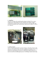
Implementation of Real‐time control system using SHARK kernel Hardware Setup The hardware setup of the real‐time control system consists of a PC computer, an ISA MultiQ‐3 data acquisition board, amplifiers, a DC servo‐motor and a 3DOF helicopter. Each of these components will be briefly described below. 1. Computer As shown in Figure1, A standard PC serves as the controller for the real‐time control system. It means it is responsible for the computation of control update, receiving the sampling data from the A/D convertor and send the control output to the D/A convertor. It has a Pentium III processor, 256M RAM and runs Free‐ DOS system. Figure 1. Computer 2. MultiQ3 data acquisition board The MultiQ‐3 is a general purpose data acquisition board with 8 analog inputs, 8 analog output, 16 bits of digital input, 16 bits of digital output and up to 8 encoder inputs decoded in quadature. The system is accessed through the PC ISA bus and is adressable via a 16 consecutive memory mapped locations which are selected through a DIP switch located on the board. The MultiQ‐3 board consists an main board which reside inside the PC by inserting it into the ISA slot, and a terminal board which is an extensive part of the main board to interact with other components, as shown in Figure 2.1 and 2.2. Figure 2.1 MultiQ‐3 Main Board Figure 2.2 MultiQ‐3 terminal Board 3. Amplifiers Since we are dealing with controlling phsical plant including DC Servo‐motor and Helicopter using standard PC, power amplifiers are needed to supply enough power to drive the plant. The power mudules PA‐0103 and UMP 2405 are used for driving DC motor and helicopter respectively. See Figure 3.1 and 3.2 for a snapshot. Figure 3.1 PA‐0103 Figure 3.2 UMP 2405 4. DC Servomotor The DC servo-motor model SRV-02 is shown in Figure 4. The plant consists of a DC motor in a solid aluminum frame. The motor is equipped with a gearbox. The gearbox output drives external gears. The basic unit is equipped with a potentiometer to measure the output/load angular position. It is also equipped with an optical encoder used to measure the load shaft angular position. It offers high resolution (4096 counts in quadrature), and measures the relative angle of the shaft. Figure 4 SRV‐02 Motor 5. 3DOF Helicopter The 3DOF Helicopter consists of a base upon which an arm is mounted. The arm carries the helicopter body on one end and a counterweight on the other. The arm can pitch about an “elevation” axis as well as swivel about a vertical (travel) axis. Encoders mounted on these axes allow for measuring the elevation and travel of the arm. Two motors with propellers mounted on the helicopter body can generate a force proportional to the voltage applied to the motor. The helicopter is shown in Figure 5. Figure 5. 3DOF Helicopter Besides the hardware components that are listed above, the system cable connection scratches for the real‐time control system (DC motor and Helicopter) are shown in Figure 6.1 and Figure 6.2 Figure 6.1 Cable Connection for Motor control system Figure 6.2 Cable Connection for Helicopter control system Implementation of Real‐time control system using S.Ha.R.K. kernel Software part I Cong Chen [email protected] The S.Ha.R.K(Soft and Hard Real-time Kernel) kernel is basically a set of libraries , that the developers can statically link together to form an application (bootable image). The application is executed using the X.EXE DOS memory extender under the DOS operating system or directly run when the system is booted using GRUB. The S.Ha.R.K. kernel provides various kernel-level services that application developer scan call at the development stage, including task management, context switching, scheduling algorithms, etc. It has also provided drivers for most common computer hardware, so that the developer can focus more on the application level instead of worrying about the interaction between the hardware and software. For more details about the SHARK kernel, please refer to the Document vol1 and vol4, which you can download at the homepage of S.Ha.R.K. project: http://shark.sssup.it/. Typically developing an S.Ha.R.K. application involves two major software components: an initialization file and a program source file. The initialization file is responsible for initializing the device drivers, registering the modules needed (both scheduling and resource modules), including the headfiles, etc. The program sources file is where the classical main entrance function resides. The main function will be automatically called after the application starts. Here we list a simple application to briefly explain these two major components. The application will simply print “Hello world” in the screen. Comments are included to help understand the functionality of these subroutines. HelloWorld Application: 1. Initialization file /*including necessary system head*/ #include "kernel/kern.h" #include "rr/rr/rr.h" #include "dummy/dummy/dummy.h" /*+ sysyem tick in us +*/ #define TICK 300 /*+ RR tick in us +*/ #define RRTICK 10000 /*The kernel calls this function to register the modules that will be used in this application*/ TIME __kernel_register_levels__(void *arg) { struct multiboot_info *mb = (struct multiboot_info *)arg; /*The round-robin and dummy scheduling modules are registered */ RR_register_level(RRTICK, RR_MAIN_YES, mb); dummy_register_level(); /* a TICK value (in microseconds) is returned, which is the time will be used for programming the periodic timer interrupt of the PC*/ return TICK; } /*This function is called to initialize the device drivers(keyboard, graphic, etc.) and modules*/ TASK __init__(void *arg) { struct multiboot_info *mb = (struct multiboot_info *)arg; /*Initialize the Hartik Port Layer*/ HARTPORT_init(); __call_main__(mb); return (void *)0; } 2. Program source file /*Including system head*/ #include "kernel/kern.h" int main(int argc, char **argv) { /*The main function simply display string “Hello, world” on the screen (console print) and switch to new line*/ cprintf("Hello, world!\n"); return 0; } Now you might have the idea about what does an S.Ha.R.K application look like. Then you are on your way to build your own application and we’ll show you how to compile, build and execute your application step by step. Typically, the development environment for S.Ha.R.K application could be either Linux or DOS. In Lab A63, we develop the application in those computers running RedHat Linux Workstation version. There are several C source code editing tools that are available under Linux system, including emacs, vim, gedit, etc. You can choose either editing tool based your own preference. The GCC compiler will be used to compile your C source code under Linux. It has already been installed and upgraded to the latest version, which is GCC4. Before you start working on your own application, make sure that the S.Ha.R.K kernel, libraries, modules and common device drivers have been correctly built in the system (Check out http://shark.sssup.it/ for more details about how to build SHARK kernel). After you have done editing your S.Ha.R.K. application, the next step is to compile all the source files and link them together with the required libraries to form an executable image. In Linux system, using the GNU makefile utility, you can complete this process by simply typing “make” in the command line. The makefile is a special script file that can be invoked by the “make” command (if you don’t know makefile at all, check out the official GNU site for make utility). A typical makefile example for S.Ha.R.K. application is shown as followed: 1 2 3 4 5 6 7 8 9 10 11 12 # # makefile # ifndef BASE BASE=../.. endif include $(BASE)/config/config.mk PROGS= App_Name include $(BASE)/config/example.mk App_Name: make -f $(SUBMAKE) APP=App_Name OTHEROBJS="source2.o source3.o " SHARKOPT="__LINUXC26__ __PCI__ __INPUT__ __FB__" The example makefile is trying to build an application called App_Name. In this application, the main function is included in the source file App_Name.c. The other source files, including source2.c and source3.c in this case, should also be contained to build the App_Name application. To compile these other source files you should put the name of the source files with the “.o” extension(not “.c” extension) in the field after “OTHEROBJS=” shown in the example. The compiler will automatically compile all the .c source file (including App_Name.c). So if you are going to develop an application called my_app, you should replace “App_Name” in the example file at line 8, 10 and 11 with your application name “my_app”. You should also replace the source2.o and source3.o with the name of the other source files (appended with “.o” extension). For instance, if you have only one other source file initfile.c other than my_app.c, you should replace “source2.o source3.o” with “initfile.o”. After you modify the makefile in order to build your own application with the name you identify, you can now type “make” command in the terminal under the application directory. If the make process is successful, an executable file will be generated within the current directory. Otherwise, some error messages generated by the compiler will appear in the terminal and you have to reexamine your source codes to fix the corresponding problem. Since the application cannot run in the Linux Desktop, we’ll need a floppy to copy the executable file to the target machine running the FreeDOS system. In Linux console, type the following command to mount the floppy, mount /mnt/floppy Before doing this, make sure the floppy has already been inserted into the computer. Then you can type cp /AppDirectory/my_app /mnt/floppy AppDirectory represents the directory you build the application. After finishing copying, type umount /mnt/floppy to unmount the floppy. Then you can insert the floppy to the target computer and access the floppy driver in FreeDOS by typing the command B:/ and you should be in the Floppy directory. Finally you can run your application by typing X my_app That’s basically all you need to do to compile and execute an S.Ha.R.K application. Really simple, isn’t it? Note that there is an alternative way to execute the application in the target machine. You can use the A: drive, which is a high speed RAM cache, to run the executable. Basically you only need to explicitly copy the executable file from the floppy drive (B:) to A drive by typing A:/ copy B:\my_app X my_app Then you’ll notice that the executing speed of the application is enhanced significantly (cause you are reading the memory now instead of reading the floppy drive). Implementation of Real‐time Control system using S.Ha.R.K. kernel Cong Chen [email protected] Software Part II The S.Ha.R.K. kernel has made available device drivers of most computer hardware for application developers, including keyboard input, graphic card, network card, USB device, etc. The source files of these drivers reside in the “driver” folder under Shark kernel’s root directory. For more information about the device drivers and programming libraries, see the S.Ha.R.K. User Manual Volume II for details (which you can download at http://shark.sssup.it/). In our implementation, as we mentioned in previous section, we use MultiQ3 data acquisition board to perform conversion between analog signal and digital signal. We need to develop the driver for MultiQ3 board that is compatible with S.Ha.R.K. kernel. The driver should be able to provide services containing analog to digital input, digital to analog output, encoder input, etc. For servo motor control experiment, we only need the first two services to control the motor and collect data from the motor’s sensor. In the helicopter experiment, since the sensor data are measured with encoders, we’ll further need to write the encoder input routine in the driver to properly control the helicopter. In the following discussion, we’ll list the MultiQ3 driver source code for S.Ha.R.K. kernel, as well as the process to integrate the driver into the kernel so the application developer can access the driver function in a quite easy way. 1. MultiQ driver source code /* multiq.c driver of multiQ3 board for SHaRK */ #include "math.h" #include <kernel/kern.h> #define base_port 0x320 #define digin_port #define digout_port #define dac_cs #define ad_cs #define status_reg #define control_reg #define clk_reg #define enc_reg1 #define enc_reg2 #define AD_SH base_port + 0x00 base_port + 0x00 base_port + 0x02 base_port + 0x04 base_port + 0x06 base_port + 0x06 base_port + 0x08 base_port + 0x0c base_port + 0x0e 0x200 #define AD_AUTOCAL #define AD_AUTOZ #define AD_MUX_EN #define AD_CLOCK_4M 0x100 0x80 0x40 0x400 #define CONTROL_MUST (AD_SH | AD_CLOCK_4M) #define BP_RESET 0X01 #define TRSFRCNTR_OL 0X10 #define CLOCK_DATA 0 #define CLOCK_SETUP 0x18 #define INPUT_SETUP 0x41 #define QUAD_X4 0x38 #define CNTR_RESET 0x02 #define EFLAG_RESET 0x06 unsigned short control_word = CONTROL_MUST; //Interger(16bit) to voltages (-5 – 5v) conversion float itov(int iv) { return ( 5*( (float) iv/4095.)); } // voltages (-5 – 5v) to Interger(16bit) conversion int vtoi(float v) { return(ceil( v*2048/5.+2047)); } //Read the analog to digital input int adin( int ch) { unsigned short hb,lb; short toolong,maxcnt; maxcnt = 30; // nosound(); control_word = CONTROL_MUST | AD_MUX_EN | (ch<<3); outpw(control_reg, control_word); toolong = 0; while( ((inpw(status_reg)&0x8) == 0x00 ) && (toolong < maxcnt) ) toolong++; outpw(control_reg, control_word); toolong = 0; while( ((inpw(status_reg)&0x8) == 0x00 ) && (toolong < maxcnt) ) toolong++; //if(toolong >= maxcnt) sound(400); outp(ad_cs,0); while( (inpw(status_reg)&0x10) == 0x00 ); hb = inp(ad_cs) & 0xff; lb = inp(ad_cs) & 0xff; outpw(control_reg,CONTROL_MUST); return ( (hb<<8) | lb); } //perform digital to analog output int daout( int ch, float voltage) { int ivalue; if (voltage > 5) voltage = 5; else if (voltage < -5) voltage = -5; else ivalue = vtoi(voltage); outpw( control_reg, 0x1800 | ch | CONTROL_MUST); outpw( dac_cs, ivalue); outpw( control_reg, CONTROL_MUST); return 0; } // Read encoder input int enc_in(int ch) { unsigned char low_byte, mid_byte, high_byte; unsigned short low_word, high_word; unsigned int result; control_word = CONTROL_MUST|AD_MUX_EN|(ch<<3); //select channel outp(control_reg, control_word); outp(enc_reg2, BP_RESET); outp(enc_reg2, TRSFRCNTR_OL); low_byte = inp(enc_reg1) & 0xff; mid_byte = inp(enc_reg1) & 0xff; low_word = (low_byte) | (mid_byte<<8) & 0xffff; high_byte = inp(enc_reg1) & 0xff; high_word = high_byte & 0xffff; if(high_word & 0x80) high_word = high_word | 0xff00; result = ((unsigned int)high_word << 16) | low_word; return (int) result; // convert to signed 32 bit } //Reset Analog to digital input channels void reset_ad(void) { outpw(control_reg, AD_AUTOCAL | CONTROL_MUST); outpw(control_reg, CONTROL_MUST); while((inpw(status_reg)&0x08)==0x00); } //Reset Digital to Analog output channels void reset_da(void) { float zero_v; zero_v = 0.0; daout(0, zero_v); daout(1, zero_v); daout(2, zero_v); daout(3, zero_v); daout(4, zero_v); daout(5, zero_v); daout(6, zero_v); daout(7, zero_v); } // reset encoder channels void enc_reset( int ch) { //outpw(enc_reg1, ch); //if( (ch == 0) || (ch == 2) || (ch == 4)) outp(enc_reg1,((ch&0x07)|0x8)); //if( (ch == 1) || (ch == 3) || (ch == 5)) outp(enc_reg1,((ch&0x07)|0x10)); control_word = CONTROL_MUST | (ch<<3); outp(control_reg, control_word); outp(enc_reg2, EFLAG_RESET); outp(enc_reg2, BP_RESET); outp(enc_reg1, CLOCK_DATA); outp(enc_reg2, CLOCK_SETUP); outp(enc_reg2, INPUT_SETUP); outp(enc_reg2, QUAD_X4); outp(enc_reg2, CNTR_RESET); } //Read digital input int digin(void) { return inpw(digin_port); } //Perfom digital output void digout(int dig_value) { outpw(digout_port, dig_value); } 2. Compiling the driver Assume the driver source file is named “multiq.c”, we need a head file containing the function declarations for the source file. Create a head file named “multiq.h”, and the content should look like this: #ifndef _MY_MULTIQ_ #define _MY_MULTIQ_ #include "ll/sys/cdefs.h" __BEGIN_DECLS float itov(int iv); /* integer to voltage */ int vtoi(float v); /* voltage to integer */ int adin(int ch); /* analog to digital (in) */ int daout (int ch, float voltage); /* digital to analog (out) */ void reset_da(void); void reset_ad(void); int digin (void); /* digital input */ void digout (int dig_value); /* digital output */ __END_DECLS #endif Then we should put these files in the “drivers” directory within the shark folder. Go to the “drivers” directory and create a new folder named “multiq”. Copy the “multiq.c” file into the “multiq” folder and create a new folder called “include”. Go to the include folder and create a new folder called “drivers”. Then copy the “multiq.h” file into the “drivers” directory that is just created. We’ll then move on to compile the source code to produce the object file that can be used by application developers. Create a makefile in “multiq” directory. In this case, our makefile has the following content: # The MultiQ library ifndef BASE BASE=../.. endif include $(BASE)/config/config.mk LIBRARY OBJS_PATH = multiq = $(BASE)/drivers/multiq OBJS = multiq.o include $(BASE)/config/lib.mk After you finish editing the makefile, type “make” command in the terminal (make sure you are currently in the “multiq” directory). The compiler should produce two new files called “multiq.o” and “libmultiq.a”. The “multiq.o” is an object file compiled from the original “multiq.c” source file. The “libmultiq.a” is a library file can be added into the shark library and referred by the developer. Now the driver source file has been successfully compiled, we’ll show how to integrate the driver into the shark library so that the application developer can call the driver routine without caring much about the driver itself. 3. Integrating the driver into the S.Ha.R.K. library In the previous section, you probably have noticed that, in the sample makefile for developing an S.Ha.R.K. application, the device drivers is used by identify SHARKOPT="__LINUXC26__ __PCI__ __INPUT__ __FB__". This means that the application is going to use the Linux 2.6 compatibility layer, which is always required when the drivers are used, the PCI driver, the Input driver (to manage the input devices like keyboard, mouse, etc.) and the Frame Buffer driver for the graphical display. The list of all the available libraries can be found into the “Lib” directory within shark folder. In order to use the MultiQ driver in the similar, meaning by add “__MULTIQ__ “ into the SHARKPORT string, we have to do the following two steps. Firstly, copy the “libmultiq.a” file we get after compiling into the “lib” directory within the “shark” folder to make the MultiQ library available to application developer. Second, go to the “config” directory within the “shark” folder and open a file called “libdep.mk”. Add following content into the file, # MultiQ # ---------------------------------------------------------------ifeq ($(findstring __MULTIQ__,$(USELIB)) , __MULTIQ__) INCL += -I$(BASE)/drivers/multiq/include ifeq ($(LIB_PATH)/libmultiq.a,$(wildcard $(LIB_PATH)/libmultiq.a)) LINK_LIB += -lmultiq LIB_DEP += $(LIB_PATH)/libmultiq.a endif Then save the file, it’s done! 4. Using the driver After all the previous work, finally it’s time to user the MultiQ driver. Recall that we have discussed in the precious section, typically an S.Ha.R.K. application has two major software component: the initialization file and the program source file. In order to use the driver properly, we need to first explicitly include the driver head file in the program source file. In this case, for instance we use my_app.c as the source file, the following content should be contained in the beginning of the program source code to include the driver head file. #include <drivers/multiq.h> In addition, as mentioned previously, we should also explicitly add “__MULTIQ__” to the SHARKPORT string to tell the compiler to locate the MultiQ library in the “lib” directory. The result should look like this, SHARKOPT="__LINUXC26__ __PCI__ __INPUT__ __FB__ __MULTIQ__". Then you are free to call any driver function in your application. Have fun! Implementation of Real-time control system using S.Ha.R.K. kernel Cong Chen Department of Electrical Engineering University of Norte Dame [email protected] Software 3 In this section, we are going to explain the helicopter control application, with emphasis on the software program. The purpose of developing the helicopter real-time control application is that we can further perform experiment to explicitly evaluate the eventtrigger control approach and the traditional periodic-trigger control approach on a 3DOF helicopter model based on the experimental platform we built. The platform contains several hardware components we mentioned earlier in previous section, as well as an S.Ha.R.K. application that runs on a computer serving as the real-time controller. In the following discussion, we will briefly introduce the hardware components as well as the software function. The hardware setup for the helicopter real-time control application consists of a computer running DOS operating system, a MultiQ3 data acquisition board, two UMP 2405 power amplifiers and a 3DOF helicopter model. The system diagram and relationship between each component is shown in Fig 4.1. Computer (control task) MultiQ 3 board Power Amplifier 3DOF Helicopter Figure 4.1 Hardware diagram As figure 4.1 shows, the control signal is produced by control task being executed by the Computer’s CPU. Through the MultiQ3 board, the output digital signal is converted into analog signal. In order to drive the motors in the 3DOF helicopter, the outputs of the D/A convertor are then applied to the helicopter using power amplifiers. Similarly, the sensor data collected from the helicopter model (the encoders) goes through the MultiQ3 board so that the computer is able to process and update the control computation. The software program of the helicopter control application consists of several concurrently running tasks. Typically, the real-time tasks can be divided into two categories, hard task and soft task. Hard tasks normally perform critical actions and have strict timing condition constraints (deadline), which might include control computation task, event detector task, etc. Comparing to hard tasks, soft tasks have relatively loose constraint in terms of deadlines, which means that missing deadlines is tolerable to some extent and will not cause system failure. These tasks usually include screen graphic tasks, statistic data collection task, keyboard input task, and etc. In our helicopter control application, we’ll have three hard tasks and three soft tasks. The hard tasks are helicopter control task, event detector task, and a graphic task that can be triggered by user input. The reason for having a graphic hard task here is that we can simulate multiple control-loop environment by simply adding graphic hard task instead of introduce new control plant, which is not necessary to conduct the experiment. The soft tasks are task execution statistics collection task, system load estimation task and a graphic soft task. The graphic soft task is very similar to the graphic hard task. Both of them will simply move an object on the screen horizontally and the only difference is the object shape and moving speed. The hard task model is a moving box while the soft one is a moving circle. In this uni-processer real-time system, single CPU is shared by various tasks running at the same time. Scheduling algorithms are used to allocate the CPU resource to different tasks and guarantee that the timing constraints can be meet. In this application, we use EDF (Earliest Deadline First) scheduling algorithm to schedule hard tasks and RRSoft (Round Robin for soft tasks) scheduling algorithm to schedule the soft tasks. General RR (Round Robin) algorithm is used to schedule the non-realtime tasks. The scheduling algorithms can be identified in the initialization file and registered at run time when the program starts. The main program is listed as followed. The program is self-explanatory since comments have been added for each block. /* S.Ha.R.K. application for real-time 3DOF Helicpter * control system with both periodic trigger and event-trigger approach * * A63 System & Control Lab * Department of Electrical Engineering * University of Notre Dame * Program Writer: Cong Chen * */ #include #include #include #include #include <kernel/kern.h> <sem/sem/sem.h> <stdlib.h> <math.h> <fs/syscall.h> #include #include #include #include <drivers/shark_linuxc26.h> <drivers/shark_keyb26.h> <drivers/shark_fb26.h> <drivers/multiq.h> #include #include #include #include #include <kernel/func.h> <kernel/descr.h> <edf/edf/edf.h> <kernel/model.h> <kernel/var.h> #define DEBUG #define #define #define #define #define #define #define #define #define CHN_IN 4 CHN_OUT 6 CHN_IN_TRV 0 CHN_IN_PTH 1 CHN_IN_ELV 2 CHN_OUT_FRT 0 CHN_OUT_BCK 1 CHN_JOYX 2 CHN_JOYY 3 // // // // // // // #define #define l task #define #define #define #define #define #define PERIOD_CTRLLER 100000 WCET_CTRLLER 2000 // Period for control task (In microseconds) // WCET(worst case execution time for contro PERIOD_JETDUMMY 100000 WCET_JETDUMMY 400 WCET_JETCTRLLER 400 PERIOD_JETCTRLLER 100000 PERIOD_EVENT_DET 5000 WCET_EVENT_DET 2000 // Period for event detector task // WCET for event detector task #define HVEL #define SVEL #define MAX_T 5 3 50 Encoder Input Channel for travel Encoder Input Channel for pitch Encoder Input Channel for elevation Output Channel for Front propeller Output Channel for Back propeller Input Channel for Joystick-X Input Channel for Joystick-Y // Velocity for Hard box task // Velocity for Soft circle task // Max number of addable tasks // Parameters to draw the display senario #define #define #define #define #define #define #define #define XMIN XMAX YMIN YMAX YCTL XMID D YMID 100 540 30 450 250 300 3 260 // Parameters for jet_dummy task #define DUMMY_PID 2 #define JET_DUMMY_WIDTH 210 #define JET_DUMMY_HEIGHT 80 #define JET_DUMMY_X 110 #define JET_DUMMY_Y 160 #define JET_SLIDE_WIDTH 50 #define JET_SLIDE_X 576 #define PI 3.1415926 #define LEN 25 float gain double Kep double Kpp double Ked double Kei double Kpd = = = = = = // lowpass filter length 1; 0; 0; 0; 0; 0; // useful colors int white; int black; int red; int gray; PID controller_PID; PID jet_dummy_PID; PID event_PID; int int int int PID hard_period soft_period hard_wcet = soft_wcet = pid; = 5000; = 10000; 500; 500; // // // // // desire output float desire_out_f = 0.0; float desire_out_b = 0.0; // Mutex for accessing the print utility sem_t prt_mutex; // Count for graphic task numbers int h_count; int s_count; Hard Soft Hard Soft graphic graphic graphic graphic task task task task period period WCET WCET // Task model HARD_TASK_MODEL m; SOFT_TASK_MODEL n; int travel_c, pitch_c, elevation_c; float travel, pitch, elevation; float curr_vel_trv, curr_vel_pth, curr_vel_elv; float Kf[5] = { -1.7, -0.79, -0.97, -1.09, 0.65 }; otor float Kb[5] = { -1.69, -0.77, 0.98, 1.10, -0.78 }; tor float travel_offset= 0; float pitch_offset = 0; float elevation_offset = 0; // // // // encoder input (counts) actual value (in radius) current velocity control gain for front m // control gain for back mo // State feedback control gain float gain_elevation = 0; float gain_pitch = 0; float gain_travel =0; float gain_elevation_def = 0; float gain_pitch_def = 0; float gain_travel_def = 0; // Helicopter state 1: // value 0: cruise control status Value 1: accelerate Value -1: deccelerate int heli_state_1 = 0; // Helicopter state 2: // value 0: cruise control status Value 1: increse pitch angle by 0.3 radius, Val ue -1: decrease pitch angle by 0.3 radius int heli_state_2 = 0; // EDF task descriptor typedef struct { int flags; TIME period; TIME rdeadline; TIME offset; struct timespec release; struct timespec adeadline; int dl_timer; int eop_timer; int off_timer; int dl_miss; int wcet_miss; int act_miss; int nact; } EDF_task_des; // Level descriptor typedef struct { level_des l; int flags; /* /* /* /* /* /* /* /* /* /* /* /* /* task flags period (or inter-arrival interval) relative deadline release offset release time of current instance latest assigned deadline deadline timer end of period timer timer offset deadline miss counter WCET miss counter activation miss counter number of pending periodic jobs /* standard level descriptor /* level flags */ */ */ */ */ */ */ */ */ */ */ */ */ */ */ IQUEUE ready; bandwidth_t U; EDF_task_des tvec[MAX_PROC]; } EDF_level_des; /* the ready queue /* used bandwidth /* vector of task descriptors */ */ */ // Helicopter control task TASK servo_ctrl(void *arg) { float ctrller_f, ctrller_b; //front and back propeller controller char str1[100]; char str2[100]; char str3[100]; char str4[100]; float JoyY; float JoyX; while(1) { // Read Joystick input JoyX = itov((short)adin(CHN_JOYX)); JoyY = itov((short)adin(CHN_JOYY)); // Set the status of the helicopter to deccelerate if user pull the joystick down, at the same time release the traval control loop if ((heli_state_1 == 0) && (JoyY <= -2.5)) { heli_state_1 = -1; gain_travel = 0; } // Set the status to accelerate if user push joystick up and realease the tra vel control loop else if ((heli_state_1 == 0) && (JoyY >= 1)) { heli_state_1 = 1; gain_travel = 0; } // Set the status to cruise control if user stop using the joystick, reset th e travel gain and offset to maintain current state. else if ( (JoyY < 0.5 ) && (JoyY > -2.0) && (heli_state_1 != 0)) { heli_state_1 = 0; gain_travel = gain_travel_def; travel_offset = curr_vel_trv; elevation_offset = elevation; } // If the user pulls the joystick to the left, the desired pitch angle decrea ses by 0.3 radius if ( (JoyX <= 1) && (heli_state_2 == 0) ) { pitch_offset += -0.3; heli_state_2 = -1; } // If the user pulls the joystick to the right, the desired pitch angle incr eases by 0.3 radius else if ( (JoyX >= 3) && (heli_state_2 == 0)) { pitch_offset += 0.3; heli_state_2 = 1; } // If the user dosen't pull the joystick in the horizental dicrection (X), it maintains cruise control status else if ((JoyX > 1.2)&&(JoyX < 2.8) && (heli_state_2 != 0)) { heli_state_2 = 0; } // The state feedback control output computation, for front motor and back mo tor separately ctrller_f = (gain_elevation *(Kf[0] * curr_vel_elv + Kf[1] * (elevation - ele vation_offset)) + gain_pitch * (Kf[2] * curr_vel_pth + Kf[3] * (pitch -pitch_off set)) + gain_travel * Kf[4] * (curr_vel_trv - travel_offset)) ; ctrller_b = ( gain_elevation* (Kb[0] * curr_vel_elv + Kb[1] * (elevation - el evation_offset)) + gain_pitch * (Kb[2] * curr_vel_pth + Kb[3] *( pitch - pitch_of fset)) + gain_travel * Kb[4] * (curr_vel_trv - travel_offset)); // If the current status of the helicopter is accelerating, the control gain depends on the joystick input, otherwise the control gains are updated in the pre vious computation if (heli_state_1 ==1 ) { JoyY = (JoyY - 1)/3.0; ctrller_f += JoyY*4; ctrller_b += JoyY*4; } else if (heli_state_1 == -1 ) { JoyY = (JoyY - (-2.5))/3.2; ctrller_f += JoyY*4; ctrller_b += JoyY*4; } // Make sure the absolute value of output voltage is not larger than 5 if (ctrller_f <= -4.99) ctrller_f = -4.99; else if (ctrller_f >= 4.99) ctrller_f = 4.99; if (ctrller_b <= -4.99) ctrller_b = -4.99; else if (ctrller_b >= 4.99) ctrller_b = 4.99; // Output the control signal to MultiQ board daout(CHN_OUT_FRT, ctrller_f); daout(CHN_OUT_BCK, ctrller_b); // Print the control information in the screen sem_wait(&prt_mutex); sprintf(str1,"travel: %6d, pitch: %6d, elevation: %6d", travel_c, pitch_c, el evation_c); sprintf(str2,"the output of the travel rate controller is %8.6f, %8.6f", ctrl ler_f, ctrller_b); sprintf(str3,"curr_vel_elv: %6.4f, curr_vel_pth: %6.4f, curr_vel_trv: %6.4f", curr_vel_elv, curr_vel_pth, curr_vel_trv); sprintf(str4,"travel: %8.5f, pitch: %8.5f, elevation: %8.5f", travel, pitch, elevation); grx_text(str1, XMIN, YMIN+70, gray, black); grx_text(str2, XMIN, YMIN+80, gray, black); grx_text(str3, XMIN, YMIN+90, gray, black); grx_text(str4, XMIN, YMIN+100, gray, black); sem_post(&prt_mutex); task_endcycle(); } } // Event detector task TASK event_det(void *arg) { /* float Q[2][2] = {{1, 0.9},{0.9, 0.81}}; float beta = 0.5; float M[2][2]; float N[2][2]; M[0][0] = (1-beta*beta)+Q[0][0]; M[0][1] = Q[0][1]; M[1][0] = Q[1][0]; M[1][1] = (1-beta*beta)+Q[1][1]; N[0][0] = 1.0/2*(1-beta*beta)+Q[0][0]; N[0][1] = Q[0][1]; N[1][0] = Q[1][0]; N[1][1] = 1.0/2*(1-beta*beta)+Q[1][1]; */ int prev_trv_c , prev_pth_c, prev_elv_c; float prev_vel_trv, prev_vel_pth, prev_vel_elv; float vel_elv, vel_pth, vel_trv; // Array for low pass filter implementation float filt1[LEN]; float filt2[LEN]; float filt3[LEN]; // Parameters // Previous encoder input // Previous velocity // Current velocity long k = 0; int i = 0; float sum1 = 0; float sum2 = 0; float sum3 =0; #ifdef DEBUG char str[100], str1[100]; #endif TIME cmax, csum; int n; // Initialization prev_trv_c = 0; prev_pth_c = 0; prev_elv_c = 0; prev_vel_trv = 0; prev_vel_pth = 0; prev_vel_elv = 0; while(1) { // Read the encoders input travel_c = enc_in(CHN_IN_TRV); pitch_c = enc_in(CHN_IN_PTH); elevation_c = enc_in(CHN_IN_ELV); // Transform counter value to radius value travel = (travel_c)/8192.0 * 2*PI; pitch = (pitch_c/4096.0)* 2* PI; elevation = (elevation_c)/4096.0 *2 *PI; // Compute the velocity of elevation, pitch and travel vel_elv = (elevation_c - prev_elv_c)/ ((float)PERIOD_EVENT_DET/1000000.0) / 4096.0 * 2* PI; vel_pth = (pitch_c - prev_pth_c)/ ((float)PERIOD_EVENT_DET/1000000.0) / 409 6.0 * 2 * PI; vel_trv = (travel_c - prev_trv_c)/ ((float)PERIOD_EVENT_DET/1000000.0) / 81 92.0 * 2 * PI; // Low pass filter if (k < LEN) { sum1 = 0; sum2 = 0; sum3 = 0; filt1[k] = vel_elv; filt3[k] = vel_pth; filt2[k] = vel_trv; for (i=0;i<=k;i++) { sum1 += filt1[i]; sum2 += filt2[i]; sum3 += filt3[i]; } curr_vel_elv = sum1/(k+1); curr_vel_pth = sum2/(k+1); curr_vel_trv = sum3/(k+1); } else { curr_vel_elv = prev_vel_elv+ vel_elv/LEN - filt1[0]/LEN; curr_vel_pth = prev_vel_pth+ vel_pth/LEN - filt2[0]/LEN; curr_vel_trv = prev_vel_trv+ vel_trv/LEN - filt3[0]/LEN; for (i=0; i<LEN-1; i++) { filt1[i] = filt1[i+1]; filt2[i] = filt2[i+1]; filt3[i] = filt3[i+1]; } filt1[LEN-1] = vel_elv; filt2[LEN-1] = vel_pth; filt3[LEN-1] = vel_trv; } k++; // Update the previous state value prev_elv_c = elevation_c; prev_pth_c = pitch_c; prev_trv_c = travel_c; prev_vel_elv = curr_vel_elv; prev_vel_pth = curr_vel_pth; prev_vel_trv = curr_vel_trv; with current value task_endcycle(); } } // This task is responsible for collecting information of the current system load and displaying results on the screen TASK jetdummy_task(void *arg) { TIME now_dummy, last_dummy, diff_dummy, slice; struct timespec now, last, diff; float f_now_dummy, f_last_dummy, f_diff_dummy, f_slice; int x = 0; int height; char s[50]; NULL_TIMESPEC(&last); last_dummy = 0; for (;;) { task_nopreempt(); jet_getstat(DUMMY_PID, NULL, NULL, NULL, &now_dummy); sys_gettime(&now); task_preempt(); SUBTIMESPEC(&now, &last, &diff); slice = diff.tv_sec * 1000000 + diff.tv_nsec/1000; diff_dummy = now_dummy - last_dummy; height = (int)(JET_DUMMY_HEIGHT*((float)diff_dummy)/((float)slice)); #ifdef DEBUG f_diff_dummy=(float)diff_dummy; f_now_dummy = (float)now_dummy; f_last_dummy = (float)last_dummy; f_slice = (float)slice; sprintf(s,"the height is %d, diff_dummy is %f, last is %f, now is %f, slice i s %f", height, f_diff_dummy, f_last_dummy, f_now_dummy, f_slice); grx_text(s, XMIN, YMAX, gray, black); #endif TIMESPEC_ASSIGN(&last, &now); last_dummy = now_dummy; grx_line(JET_DUMMY_X+x,JET_DUMMY_Y, JET_DUMMY_X+x,JET_DUMMY_Y+height ,black); grx_line(JET_DUMMY_X+x,JET_DUMMY_Y+height, JET_DUMMY_X+x,JET_DUMMY_Y+JET_DUMMY_HEIGHT,white); grx_line(JET_DUMMY_X+(x+1)%JET_DUMMY_WIDTH,JET_DUMMY_Y, JET_DUMMY_X+(x+1)%JET_DUMMY_WIDTH,JET_DUMMY_Y+JET_DUMMY_HEIGHT,255); x = (x+1)%JET_DUMMY_WIDTH; task_endcycle(); } } // A jet task to collect control task and event-detector task execution informati on and display on the screen TASK jet_ctller(void *arg) { TIME sum, max; char st[50],st2[50], st1[50]; int n; EDF_level_des *lev = (EDF_level_des *)level_table[proc_table[controller_PID].ta sk_level]; for (;;) { // Get the mean execution time, max execution time (In microseconds) and nu mbers of missing deadlines for control task if (jet_getstat(controller_PID, &sum, &max, &n, NULL)!=-1) { if (!n) n=1; sprintf(st, "%6d %6d %10s", (int)sum/n, (int)max, proc_table[controller _PID].name); grx_text(st, 300, YMIN+120+16, gray, black); sprintf(st2, " task has missed %d deadlines", (lev->tvec[controller_PID ]).dl_miss); grx_text(st2, 300, YMIN+120+16+16, gray, black); } // Get the mean execution time, max execution time (in microseconds) for ev ent-detector task if (jet_getstat(event_PID, &sum, &max, &n, NULL)!=-1) { if (!n) n=1; sprintf(st1, "%6d %6d %10s", (int)sum/n, (int)max, proc_table[event_PID ].name); grx_text(st1, 300, YMIN+120+16+8, gray, black); } task_endcycle(); } } // Draw circle on the screen void draw_cir (int x, int y, int c) { grx_disc (x, y, D, c); } // Draw box on the screen void draw_box (int x, int y, int c) { grx_box (x, y, x + 4, y + 4, c); } // Graphic circle task (moving horizontally on the screen) TASK cir (void *arg) { int x, y; int ox, oy; int dx; int col, red; int outx; int i = (int) arg; x = ox = XMIN; y = oy = YMID + 2 * i; dx = HVEL; red = 100 + 10 * i; if (red > 255) red = 255; col = rgb16 (red, 0, 50); while (1) { x += dx; outx = (x >= XMAX) || (x <= XMIN); if (outx) { x = x - dx; dx = -dx; x += dx; // color of circle } sem_wait draw_cir draw_cir ox = x; oy = y; sem_post (&prt_mutex); (ox, oy, 0); (x, y, col); (&prt_mutex); task_endcycle (); } } // Graphic box task (moving horizontally on the screen) TASK box (void *arg) { int x, y; int ox, oy; int dx; int col, blue; int outx; int i = (int) arg; x = ox = XMAX-4; y = oy = YMID + 1 + 2 * i; dx = - SVEL; blue = 100 + 10 * i; if (blue > 255) blue = 255; col = rgb16 (50, 0, blue); while (1) { x += dx; outx = (x >= XMAX) || (x <= XMIN); if (outx) { x = x - dx; dx = -dx; x += dx; } sem_wait draw_box draw_box ox = x; oy = y; sem_post // color of box (&prt_mutex); (ox, oy, 0); (x, y, col); (&prt_mutex); task_endcycle (); } } // Initialize and create helicopter control task and event-detector task (Hard ta sks) void init_servo(void) { HARD_TASK_MODEL sv, ed; // Initialize the Hard task model with parameters for event-detector task hard_task_default_model(ed); hard_task_def_ctrl_jet(ed); hard_task_def_wcet(ed, WCET_EVENT_DET); hard_task_def_mit(ed, PERIOD_EVENT_DET); hard_task_def_usemath(ed); hard_task_def_group(ed,1); // Create a new event-detector task event_PID = task_create("event_detector", event_det, &ed, NULL); if (event_PID == NIL) { sys_shutdown_message("Could not create task <event_detector>"); exit(1); } // Initialize the Hard task model with parameters for helicopter control task hard_task_default_model(sv); hard_task_def_ctrl_jet(sv); hard_task_def_wcet(sv, WCET_CTRLLER); hard_task_def_mit(sv, PERIOD_CTRLLER); hard_task_def_usemath(sv); hard_task_def_group(sv,1); // Create a new helicopter control task controller_PID = task_create("servo_controller", servo_ctrl, &sv, NULL); if (controller_PID == NIL) { sys_shutdown_message("Could not create task <servo_controller>"); exit(1); } } // Draw the frame scenario on the screen void scenario(void) { grx_rect (XMIN - D - 1, YCTL - D - 1, XMAX + D + 1, YMAX + D + 1, rgb16 (0, 255 , 0)); grx_rect (XMIN - D - 1, YMIN + 60 - D - 1, XMAX + D + 1, YCTL -10 + D + 1,rgb1 6 (0, 255, 0)); grx_text ("The controller's in/out state:", XMIN, YMIN+60, rgb16(0,0,255), 0); grx_text ("system load",XMIN, YMIN+120, rgb16(0,0,255),0); grx_text(" Mean Max Name ", 300, YMIN+120, gray, black); grx_text ("Servo controller, hard circle and soft box", XMIN, YMIN + 10,rgb16 (255, 255, 255), 0); grx_text ("press 'h' create a hard circle", XMIN, YMIN + 20, rgb16 (255, 255, 2 55),0); grx_text ("press 's' create a soft box", XMIN, YMIN + 30, rgb16 (255, 255, 255) ,0); grx_text ("press 'ESC' exit to DOS", XMIN, YMIN + 40, rgb16 (255, 255, 255), 0); } // Initialize and create Soft tasks, including jet-dummy task and jet-controller task void init_jet(void) { SOFT_TASK_MODEL j1; SOFT_TASK_MODEL jc; PID pc; soft_task_default_model(j1); soft_task_def_level(j1,2); soft_task_def_period(j1, PERIOD_JETDUMMY); soft_task_def_met(j1, WCET_JETDUMMY); soft_task_def_group(j1, 1); soft_task_def_usemath(j1); soft_task_def_ctrl_jet(j1); jet_dummy_PID = task_create("jdmy", jetdummy_task, &j1, NULL); if ( jet_dummy_PID == -1) { sys_shutdown_message("Could not create task <jetdummy> errno=%d", errno); exit(1); } soft_task_default_model(jc); soft_task_def_level(jc,2); soft_task_def_period(jc, PERIOD_JETCTRLLER); soft_task_def_met(jc, WCET_JETCTRLLER); soft_task_def_ctrl_jet(jc); soft_task_def_group(jc, 1); pc = task_create("jet_ctrller", jet_ctller, &jc, NULL); if (pc == -1) { sys_shutdown_message("Could not create task <jet_ctrller> errno=%d", errno); exit(1); } } // Keyboard Callback function (Terminate control task, reset the AD/DA board and exit the application) void endfun(KEY_EVT *k) { task_kill(controller_PID); sleep(1); reset_ad(); reset_da(); exit(0); } // Keyboard Callback function ( Clean the task execution statistic data) void zerofun(KEY_EVT *k) { int i; for (i=0; i<MAX_T; i++) jet_delstat(i); } // Keyboard Callback function ( create and activate new graphic task) void hook_func(KEY_EVT *k) { switch (k->ascii) { case 'h': hard_task_default_model (m); hard_task_def_ctrl_jet (m); hard_task_def_arg (m, (void *) h_count); hard_task_def_wcet (m, hard_wcet); hard_task_def_mit (m, hard_period); hard_task_def_usemath (m); pid = task_create ("hardcircle", cir, &m, NULL); if (pid == NIL) { sys_shutdown_message ("Could not create task <hardcircle>"); exit (1); } task_activate (pid); h_count++; break; case 's': soft_task_default_model (n); soft_task_def_ctrl_jet (n); soft_task_def_arg (n, (void *) s_count); soft_task_def_met (n, soft_wcet); soft_task_def_period (n, soft_period); soft_task_def_usemath (n); pid = task_create ("softbox", box, &n, NULL); if (pid == NIL) { sys_shutdown_message ("Could not create task <softbox>"); exit (1); } task_activate (pid); s_count++; break; case 'p': desire_out_f += 0.1; desire_out_b += 0.1; break; case 'o': desire_out_f -= 0.1; desire_out_b -= 0.1; break; } } int main (int argc, char **argv) { short test_inp; float ad_inp; float test_outp; int in_channel, out_channel; char c; char str[50]; int i; // Read the program's command-line arguments and set the default gain respeciti vely if (argc == 4) { gain_elevation_def = atof(argv[1]); gain_pitch_def = atof(argv[2]); gain_travel_def = atof(argv[3]); } else exit(1); // Initialize parameters gain_travel = 0; gain_elevation = gain_elevation_def; gain_pitch = gain_pitch_def; travel_offset = 0; pitch_offset = 0; elevation_offset = 0; h_count=0; s_count=0; char pids[100]; // Userful colors white = rgb16(255,255,255); black = rgb16(0,0,0); red = rgb16(255,0,0); gray = rgb16(128,128,128); test_outp = 0; in_channel = 4; out_channel = 6; // Reset the MultiQ D/A output, A/D input and Encoders reset_da(); reset_ad(); for (i=0;i<8;i++) { enc_reset(i); } // Initialize print mutex and call initilization function to draw frame graph a nd create hard and soft tasks sem_init(&prt_mutex, 0, 1); init_servo(); init_jet(); scenario(); // Hookup keys to different Keyboad Callback functions KEY_EVT k; k.flag = 0; k.scan = KEY_H; k.ascii = 'h'; k.status = KEY_PRESSED; keyb_hook(k,hook_func,FALSE); k.flag = CNTL_BIT; k.scan = KEY_C; k.ascii = 'c'; k.status = KEY_PRESSED; keyb_hook(k,endfun,FALSE); k.flag = ALTL_BIT; k.scan = KEY_Z; k.ascii = 'z'; k.status = KEY_PRESSED; keyb_hook(k,zerofun,FALSE); k.flag = 0; k.scan = KEY_S; k.ascii = 's'; k.status = KEY_PRESSED; keyb_hook(k,hook_func,FALSE); k.flag = 0; k.scan = KEY_P; k.ascii = 'p'; k.status = KEY_PRESSED; keyb_hook(k,hook_func,FALSE); k.flag = 0; k.scan = KEY_O; k.ascii = 'o'; k.status = KEY_PRESSED; keyb_hook(k,hook_func,FALSE); // Activate the created tasks group_activate(1); return 0; }


![[Script Editor basics - v1.5] 700 KB](http://vs1.manualzilla.com/store/data/005726068_1-0a14f792b169a78eb7f0605403a4865d-150x150.png)
![[User manual (English) - v1.6] 1.7 MB](http://vs1.manualzilla.com/store/data/005855357_1-51a3ddd110ebec5d1eef2b5791ba3868-150x150.png)