1
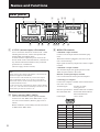
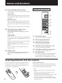
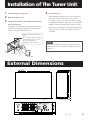
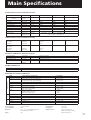
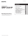
2-347-110-21 (1) CONTENTS POWERED MIXER SRP-X351P Operating Instructions Safety Information .................... 2 Main Feature .............................. 3 Names and Functions ............... 4 Installation of The Tuner Unit .. 9 External Dimensions ................ 9 Block Diagrams ......................... 10 Main Specifications .................. 11 Troubleshooting ........................ Back Cover Thank you for purchasing this Sony product. Please be sure to read this manual before using this product. After reading, keep the manual in a safe place for future reference. 1999 by Sony Sound Tec Corporation 1 Warning English Italiano WARNING ATTENZIONE To prevent fire or shock hazard, do not expose the unit to rain or moisture. Per evitare il pericolo di incendi o scosse elettriche, l’apparecchio non deve essere esposto alla pioggia o all’umidià. To avoid electrical shock, do not open the cabinet. Refer servicing to qualified personnel only. Per evitare scosse elettriche, non aprire l’apparecchio. Per le riparazioni rivolgersi solo a personale qualificato. • Operate the unit only on 230V AC, 50/60 Hz. • Far funzionare l’apparecchio con corrente alternata a 230 V, 50/60 Hz. Français AVERTISSEMENT Afin d’éviter tout risque d’incendie ou d’électrocution, ne pas exposer l’appareil à la pluie ou à l’humidité. Afin d’écarter tout risque d’électrocution, garder le coffret fermé. Ne confier l’entretien de l’appareil qu’à un personnel qualifié. • Faites uniquement fonctionner cet appareil sur une tension Norsk ADVARSEL For å hindre brann og støtfare må enhetens overflate ikke utsettes for regn eller fuktighet. For å unngå elektrisk støt må kassen ikke åpnes. Service må bare utføres av kvalifisert personell. • Enheten må bare betjenes ved 230 V vekselstrøm, 50/60 Hz. de 230 V CA, 50/60 Hz. Suomi Español ADVERTENCIA Para evitar incendios o el riesgo de electrocución, no exponga la unidad a la lluvia ni a la humedad. Para evitar descargas eléctricas, no abra la caja. En caso de avería solicite los servicios de personal cualificado solamente. VAROITUS Tulipalon ja iskuvaaran välttämiseksi ei laitetta saa altistaa sateelle ja kosteudelle. Sähköiskun välttämiseksi ei koteloa saa avata. Anna vain asiantuntijan suorittaa huolto. • Laite käyttää 230 V:n vaihtovirtaa, jonka taajuus on 50/60 Hz. • Alímente la unídad sólo con 230 V CA, 50/60 Hz. Dansk Deutsch VORSICHT Um die Feuergefahr und die Gefahr eines elektrischen Schlages zu vermeiden, darf das Gerät weder Regen noch Feuchtigkeit ausgesetzt werden. Um einen elektrischen Schlag zu vermeiden, darf das Gehäuse nicht geöffnet werden. Überlassen Sie Wartungsarbeiten stets nur einem Fachmann. ADVARSEL For at undgå faren for brand eller elektrisk stød må udstyret ikke udsættes for regn eller kraftig fugt. Åbn ikke kabinettet, da der er risiko for elektriske stød. Overlad alle reparationer til kvalificeret servicepersonale. • Betjen kun enheden med 230 V veksetlstrøm, 50/60 Hz. • Betreiben Sie das Gerät ausschließlich an 230 V Wechselspannung, 50/60 Hz. Nederlands WAARSCHUWING Stel het apparaat niet bloot aan regen of vocht, om gevaar van brand of een elektrische schok te voorkomen. Open niet de behuizing, om gevaar van elektrische shokken te vermijden. Laat reparatiles aan de erkende vakhandel over. • Last dit toestel enkel werken op 230 V wisselstroom, 50/60 Hz. Svenska VARNING Utsätt inte apparaten för regn och fukt för att undvika riskerna för brand och/eller elektriska stötar. Öppna inte höljet. Det kan resultera i risk för elektriska stötar. Överlåt allt reparations- och underhållsarbete till fackkunniga tekniker. • Du kan endast driva apparaten med 230 V växelström, 50/60 Hz. 2 Português ADVERTÊNCIA Para evitar o risco de incêndio ou de choques eléctricos, não exponha o aparelho à chuva nem à humidade. Para evitar descargas eléctricas, não abra o aparelho. Peça assistência somente a técnicos especializados. • O apparelho só deve ser utilizado com corrente de 230 V CA, 50/60 Hz. Main Feature For the customers in Europe This product with the CE marking complies with both the EMC Directive(89/336/EEC) and the Low Voltage Directive (73/23/EEC) issued by the Commission of the European Community. Compliance with these directives implies conformity to the following European standards: •EN60065 :Product Safety •EN55103-1:Electromagnetic Interference(Emission) •EN55103-2:Electromagnetic Susceptibility(Immunity) This product is intended for use in the following Electromagnetic Environment(s): E1(residential),E2(commercial and light industrial),E3 (urban outdoors) and E4(controlled EMC environment ex. TV studio). Peak inrush current (1)Power ON,current probe method: 29A (240V) (2)Hot switching inrush current, measured in accordance with European standard EN55103-1: 25A (230V) Powered Mixer Has 170W+170W(4Ω) Power Amplifier, and 4 Microphones, 3 Line Inputs. Built-in power amplifier satisfy a small PA system with 170W+170W (4Ω) output. Mixing of 4 microphone inputs and 3 stereo (line) inputs Line input (ST3) can be select 4 AV's one. Wireless Tuner Unit Can Be Installed Two UHF SYNTHESIZED TUNER UNIT WRU-801A or WRU-806A can be installed. Wireless microphone system can be easy to set up. Wireless Remote Controller supplied AV input selection, master volume and MUTING can be controlled. Simple work of Sony's CD player or MD player, Cassette Deck can be operated*. * AV equipment supplied with a wireless remote control or with Control-S terminal only Pour les clients européens Ce produit portant la marque CE est conforme à la fols à la Directive sur la compatibilité électromagnétique (EMC) (89/ 336/CEE) et à la Directive sur les basses tensions (73/23/ CEE) émises par la Commission de la Communauté européenne. La conformité à ces directives implique la conformité aux normes européennes suivantes: •EN60065 :Sécurité des produits •EN55103-1:Interférences électromagnétiques (émission) •EN55103-2:Sensibilité électromagnétique (immunité) Ce produit est prévu pour être utilisé dans les environnements électromagnétiques suivants: E1(résidentiel),E2(commercial et lndustrie légère),E3 (urbain extérieur) et E4(environnement EMC contrôlé ex. studio de télévision). Appel de courant de créte (1)Mise sous tension (ON), méthode de sondago du courant: 29A (240V) (2)Mesuré conformément à la norme européenne EN55103-1: 25A (230V) Für Kunden in Europa Exclusive Input Connectors for Recording Equipment Line input (ST2) is separated from REC bass to avoid oscillation come from flowing of its own signal. Enough Number of Input/Output Terminals, Various Function 1 The master input to connect equalizer or limiter. 2 The ECHO SEND/RETURN terminals for connect Echo equipment 3 The ASSIGN SWITCH cuts the microphone signals from MASTER OUTPUT. 4 Tone control (BASS, TREBLE), BALANCE switch of stereo/monaural and MUTING button. 5 The MIC GROUP knob for centralized control of summing signal from 4 microphone inputs. 6 The CONTROL-S terminal 7 The RS-232C REMOTE terminal 8 EIA standard 19 inch rackmountable (3U high) Dieses Produkt besitzt die CE-Kennzeichnung und erfüllt sowohl die EMV-Direktive (89/336/EEC) als auch die Dilevtive Niederspannung (73/23/EEC) der EG-Kommission. Die Erfüllung dieser Direktiven bedeutet Konformität für die folgenden Europäischen Normen: •EN60065 :Produktsicherheit •EN55103-1:Elektromagnetische Interferenz(Emission) •EN55103-2:Elektromagnetische Empfindlichkeit(Immunität) Dieses Produkt ist für den Einsatz unter folgenden elektromagnetischen Bedingungen ausgelegt: E1(Wohnbereich),E2(kommerzleller und in beschränktem Maße industrieller Bereich),E3(Stadtbereich im Freien) und E4(kontrollierter EMV-Bereich, z.B. Fernsehstudio). Spitzenstrom (1)Einschaltstrom, Stromsonde: 29A (240V) (2)Gemossen in EN55103-1: 25A (230V) 3 Names and Functions Front panel 1 2 3 MIC1 MIC2 4 MIC3 MIC4 5 ST1 ST2 6 7 8 9 0 !¡ ST3 CLIP ECHO RETURN PROTECTION EMG +45V ECHO/ AUX SEND ØON øOFF RF/ SIGNAL ØON øOFF RF/ SIGNAL SIGNAL SIGNAL SIGNAL SIGNAL SIGNAL +10 +10 +10 +5 +5 +5 0 0 0 -5 -5 -5 -15 -15 -15 -25 -25 -25 MASTER VOLUME MUTING A B C MIC GROUP MIC4 BASS D MIN !™ !£ !¢ !∞ PLAYER PLAYER/RECORDER !§ !¶ 1 POWER button Pressing it turns on the power. 2 Wireless remote control sensor It catches the signal from the infrared wireless remote control. If this sensor is covered by something, the remote control may not function correctly. Place the unit so that the sensor will be easy to receive the remote control signal. 3 ECHO/AUX SEND knob It adjusts the mixed signals after each channel fader and outputs to the ECHO SEND terminal. 4 RF/SIGNAL indicators They light up regardless of the position of channel fader when sound signal of more than -20dB to the standard input level are input. As for MIC 1/MIC 2 would be light up when it received the signal while the wireless tuner unit is installed and switch of the microphone is turned on. 5 ECHO RETURN switch When it is ON, the signal from the ECHO RETURN input are assigned to L/R and Rec Bus. 6 MUTING button Use muting outputs from MASTER OUTPUT, MASTER INSERT, ECHO SEND, MIC GROUP OUT, and SPEAKER output terminals. 4 !• !ª @º MAX TREBLE MIN MAX BALANCE L R @¡ @™ @£ 7 CLIP indicator Too high an output level will cause signal distortion and make the CLIP indicator light up. When this happens, lower the MASTER volume or the MIC/ LINE level knob until the indicator turns off. If too much signal output for an extended period, it may cause the equipment to overheat or to damage the speakers. 8 PROTECTION indicator It lights up while the protection circuit is working. When the power is turned on, it also lights up for few seconds and it turns off when the amplifier become stable. 9 EMG indicator It lights up when the unit receives a signal from the emergency broadcast facilities and turns to standby. As for EMG, refer to P. 75. 0 +48V indicator It lights up while the Phantom power (DC+48V) is supplied through the MIC input terminal. !¡ MASTER VOLUME Use to adjust the volume of MASTER OUTPUT and SPEAKER terminal. !™ MIC 4 terminal This is input terminal in front for wired microphone. If the wired microphones are connected to the MIC 4 terminals both at front and rear panel, the front input is given priority. Note : When you use the MIC 4, check the balanced connection. !ª SELECT buttons !£ MIC 1/MIC 2 fader knobs Use to adjust the mixing level of MIC 1/MIC 2. Either the wireless microphone or the wired microphone can be used in MIC 1/MIC 2. (Refer to page 6 and page 9.) When the WRU-801A or WRU-806A (optional) is put in to the tuner unit compartment at the rear panel, the wireless microphone is given priority while it is on. Use to select one of the unit connected to ST3 A to D input. S VIDEO and VIDEO signal from the selected input is directly output to the MASTER OUTPUT and the REC OUTPUT. The mixing level of the sound signal can be adjusted by ST3 fader knob. @º MIC GROUP knob !¢ MIC 3 fader knob Use to adjust the mixing level of MIC 3. Only the wired microphone can be used in MIC 3. !∞ MIC 4 fader knob Use to adjust the level of the signal after mixing in MIC 1 to 4 in a lump. The signal will be output from the MIC GROUP OUT terminal. @¡ Bass control knob Use to adjust the mixing level of MIC 4. Use to adjust low frequency among the sound from the MASTER OUTPUT or SPEAKER terminal. !§ ST1 fader knob Use to adjust the mixing level of ST1. A playback unit will be connected to it mainly. @™ TREBLE control knob Use to adjust high frequency among the sound from the MASTER OUTPUT or SPEAKER terminal. !¶ ST2 fader knob Use to adjust the mixing level of ST2. The sound signal of this channel is not output to the REC OUTPUT terminal; you can use without being bothered about oscillation from signal loop. @£ BALANCE adjustment knob Use to adjust the balance of left and right of the sound from the MASTER OUTPUT or SPEAKER terminal. Recorder/Player SRP-X351P INPUT OUTPUT ST2 When recording Note ×REC OUTPUT Sound signal of except ST2 INPUT MASTER !• ST3 Fader knob Use to adjust the level of the signal from AV equipment selected by the SELECT button stated in !ª. When the PROTECTION indicator lights up The protection circuit triggers and the PROTECTION indicator lights up in following conditions. In this case, the speaker and amplifier are protected by cutting output. • When direct-current voltage appears in the SPEAKER terminal from a malfunction. • When rated temperature of amplifier internal heat sink is exceeded. • When impedance of the connected speaker is too low, or when speaker outputs are shorted. When the above happens, turn off the POWER switch, find and fix the cause of the problem, and restart. 5 Names and Functions Rear panel 1 3 2 8 9 0 !¡ 1 ANT IN (antenna input) A/B terminals Use to connect the antenna for wireless tuner. When installing the tuner unit, connect the optional UHF antenna WRU-801A/WRU-806A. As these terminals output DC power of 9V for the booster inside of the connected antenna, connection of any antenna other than stated above may cause bad performance or a malfunction. (the max supply current is 20 mA) Note Before locating and connecting the antenna, read carefully the instructions supplied with the antenna. Incorrect location of the antenna may cause a bad reception such as intermittent sounds. If it is not easy to relocate the antenna after location, check carefully if the performance will be satisfied with the location. Use the coaxial cable of impedance 50 ohms/75 ohms (5D-FB, 5C-2V, etc.). The cable can be extended up to about 50 m with 5D-FB, and up to about 25 m with 5C-2V. 2 Tuner unit slot (MIC1, MIC2) These are for installation of the optional 800MHz wireless tuner unit WRU-801A/ WRU-806A. Up to two units can be installed. (Refer to page 9 how to install.) Before installation, read carefully also the instructions of WRU-801A/ WRU-806A. 6 4 5 6 !™!£ !¢ 7 !∞ !§ 3 REMOTE terminals CONTROL S input terminal Connect to the S output terminal of another equipment. When this terminal is plugged in, the sensor of this unit is not functioning. Input signals are directly output from control S output terminal. CONTROL S output terminal This terminal outputs the signal input from CONTROL S input terminal or the sensor. RS-232C (serial input/output) terminal Use to control this unit with a personal computer. Connecting to a computer Connect the computer to the RS-232C terminal of this unit with a cross cable. Terminal figure : D-sub 9 pin, male, inch type screw Electrical specification : Based on RS-232C standard Recommended cable : Plural leads shield cable for data communication Cable length : 15m or under 1 5 6 Pin No. 9 Signal Function 1 N.C Not connected 2 RD Received data 3 TD Transmission data 4 ER Data terminal ready 5 SG Signal line grand 6 DR Data set ready 7 RS Transmission request 8 CS Transmission approval 9 N.C Not connected 4 MASTER INSERT (Tip: output, Ring: input, Sleeve: GND) These are input/output terminals for MASTER OUTPUT. An external equipment can be inserted before master volume. This terminal receives signal from the emergency broadcast facilities and makes this unit be in standby. In this case, the EMG indicator on the front panel lights up. Select one of following two ways of connection as follows. When using the BREAK CONTACT terminal Remove the short bar and connect the Relay of the emergency broadcast facilities. When the relay is contact is breaked, all AUDIO outputs of this unit will be cut off. When using the +24V IN terminal This terminal receives signals of DC24V from the emergency broadcast facilities. When DC24V is cut off, all AUDIO outputs of this unit will be cut off. Remove the short bar of the BREAK CONTACT terminal ’ This is the input terminals for microphones. In MIC1 and MIC2, wireless microphone has priority while the tuner unit is used. (Refer to page 44.) 9 +48V button 5 EMG input terminals ‘ 8 MIC input terminals (1:GND 2:HOT 3:COLD) (+24V IN) BREAK CONTACT It supplies the Phantom power (DC+48V) to the MIC 1 - 4 terminals for condenser microphones. When it is ON, DC+48V is output for the MIC terminals except for the MIC4 on the front panel. Notes • Make sure to turn the MIC fader toward minimum before connecting or disconnecting any cable or turning the +48 button to ON. • Make sure to connect a line equipment to ST1 to ST3 inputs. • When using a microphone powered by +48V and a dynamic microphone simultaneously, the dynamic microphone may not show its performance to the full. 0 ST1/ST2 input terminals Use them for inputs from audio equipment. Connect a playback equipment mainly to ST1 and a record player to ST2. !¡ ST3 (AV) input terminals Use them for inputs from AV equipment. Each of input A to D is selected by the SELECT button on the front panel. !™ MASTER OUTPUT terminals Relay !£ REC OUTPUT terminals <- or -> ‘ ’ Signal routed through the Master Volume are output here. ‘ ’ (+24V output) The emergency broadcast facilities Signal not routed through the tone control (BASS, TREBLE), BALANCE and Master Volume are output here. Video signal is the same as for MASTER OUT signal. 6 CIRCUIT BREAKER When over-current flows into the unit, the circuit breaker cuts the power. In this case, remove the cause of over-current and reset the breaker by pressing RESET button. 7 SPEAKER output terminals Connect with the speakers. Connect + of the speaker to the red terminal and - to the black terminal. Use the speaker of 4 to 16 impedance. 7 Names and Functions !¢ ECHO SEND/RETURN terminals Remote control Connect effectors such as reverbrators and delay units to this terminal. SEND terminal This terminal outputs audio signals mixed by ECHO/ AUX SEND knob of MIC1 to MIC4 and ST1 to ST3 in monaural A B C D 1 DISC SKIP 2 CD RETURN terminals This is an input terminal for signal returned from the effector. When the ECHO RETURN switch on the front panel is set to ON, these are assigned to L and to R. Adjust the input level using effector's level controller. MD 3 TAPE DECK A 4 TAPE DECK B !∞ MIC GROUP and ASSIGN switch MASTER VOLUME MIC GROUP OUTPUT terminal It outputs signal of which level is adjusted by MIC GROUP knob. ASSIGN switch This is normally on. When this switch is set to OFF, the microphone signal for MASTER OUTPUT and SPEAKER terminals are cut off. Using this, turn it OFF when a PA system with ceiling speakers and external power amplifier. INSERT terminal (Tip: output, Ring: input, Sleeve: GND) Use it to connect an external graphic equalizer or a feedback reducer. MUTING 5 6 1 FUNCTION button Use to select one of ST3 A to D input. 2 CD deck operation buttons Use to operate the Sony CD deck. 3 MD deck operation buttons Use to operate the Sony MD deck. 4 TAPE deck operation buttons (A, B) Use to operate the Sony TAPE deck. 5 MASTER VOLUME operation knob !§ MODE switch It will be monaural when MASTER INSERT, MASTER OUTPUT and SPEAKER output are set to MONO. Use to adjust the master volume level. 6 MUTING button Use to mute the output signal from MASTER OUTPUT, MASTER INSERT, ECHO SEND, MIC GROUP OUTPUT or SPEAKER output terminals. Inserting batteries into the remote 8 You can control this unit with using the supplied remote. When to replace batteries Insert two R6 (size AA) batteries by matching the + and – With normal use, the batteries should last for about six on the batteries. When using the remote, point it at the remote sensor on the equipment. months. When the remote no longer operates the equipment, replace all the batteries with new ones. Notes • Do not leave the remote near an extremely hot or humid place. • Do not drop any foreign object into the remote casing, particularly when replacing the batteries. • Do not expose the remote sensor to direct sunlight or lighting apparatuses. Doing so may cause a malfunction. • If you don't use the remote for an extended period of time, remove the batteries to avoid possible damage from battery leakage and corrosion. Installation of The Tuner Unit 4 Turn off the power of this unit. Fix the tuner cover. Remove the tuner cover. After installation of the tuner unit, turn on the power of the unit and turn on the power of the wireless Check the up and down sides of the tuner unit, and microphone to check it is receiving. While receiving, insert it into the slot. the RF/SIGNAL indicator lights up. Note that the RF/ SIGNAL indicator will not light up when the setting The upper slot corresponds to MIC1 and the lower slot to MIC2. (Set the group and channel of the tuner unit channel of the microphone is different from the setting of the tuner unit, or when the microphone power is to same as wireless microphone's one.) consumed. Insert it deeply into the compartment. Do not insert or remove the tuner unit while the power is on. This may be cause of noise or malfunction of the connector. NOTICE To prevent breakdown or injury, do not put your hand inside of the slot except when you install or remove the tuner unit. Tuner unit Tuner cover 24 52 238 350 13 30 External Dimensions MIC1 MIC2 MIC3 MIC4 ST1 ST2 ST3 CLIP ECHO RETURN PROTECTION EMG +45V ECHO/ AUX SEND SIGNAL SIGNAL SIGNAL SIGNAL +10 +10 +10 +5 +5 +5 0 0 0 -5 -5 -5 -15 -15 -15 -25 -25 -25 MASTER VOLUME MUTING SIGNAL 57.2 ØON øOFF RF/ SIGNAL A B 132 ØON øOFF RF/ SIGNAL C MIC GROUP MIC4 D BASS MIN PLAYER MAX TREBLE MIN MAX BALANCE L R PLAYER/RECORDER 336 482 8 1 2 3 Unit ; mm 9 10 L REMOTE CONTROL S IN IR REMOTE RS-232C R CH Fader LCF Signal IND ECHO BUS MIC ASSIGN SW C D Mute MIC GROUP Main Controller A B MIC GROUP BUS ECHO ECHO ECHO ECHO ECHO ECHO RS-232C Controller CH Fader Signal IND ECHO RETURN Same as ST3 Ach ST 3 Dch L Same as ST3 Ach ST 3 Cch ECHO RETURN HA Signal IND Signal IND Same as ST3 Ach +48V LCF RF/Signal IND Same as MIC1 HA Same as MIC4 (without phone jack) ST 3 Bch R L Video S-Video R for Player/ Recorder ST 2 -10dBu -10dBu ST 3 Ach R L for Player ST 1 -10dBu MIC 4 -54dBu MIC 2 -54dBu MIC 3 -54dBu MIC 1 -54dBu +48V WIRELESS WRU-801A or WRU-806A REC R REC L MODE MONO STEREO BALANCE TREBLE BASS M MASTER +48V +48V EMG PROTECTION CLIP MASTER INSERT -5dBu -10dBu AC IN CIRCUIT BRAKER POWER SW EMG CONTROL REMOTE CONTROL-S OUT R L Video S-Video REC OUTPUT R L Video S-Video MASTER OUTPUT SREAKERS OUTPUT 125W+125W 8Ω R 170W+170W 4Ω L R L ECHO SEND -10dBu MIC GROUP INSERT -10dBu MIC GROUP OUTPUT -10dBu Block Diagrams Main Specifications AUDIO INPUT/OUTPUT SPECIFICATIONS Name MIC IN Connector Type Number of channels Standard input/output level Max input/output level Input/output impedance (REAR) XLR-3-31 4 -54dBu -24dBu 2.2kΩ (FRONT) PHONE ST1 input Phono Jack 1(Stereo) -10dBu +20dBu 20kΩ ST2 input Phono Jack 1(Stereo) -10dBu +20dBu 20kΩ ST3 input(A,B,C,D) Phono Jack 4(Stereo) -10dBu +20dBu 20kΩ Echo return input Phono Jack 1(Stereo) -10dBu +10dBu 20kΩ Mic group output Phono Jack 1 -10dBu +10dBu 470Ω Echo send Phono Jack 1 -10dBu +10dBu 470Ω Master output Phono Jack 1(Stereo) -5dBu +15dBu 470Ω Rec output Phono Jack 1(Stereo) -10dBu +10dBu 470Ω Screw type 1(Stereo) Speakers output Rated output 125W + 125W (8Ω 1kHz THD 0.1%) binding terminal 170W + 170W (4Ω 1kHz THD 0.1%) VIDEO INPUT/OUTPUT SPECIFICATIONS ST3 input(A,B,C,D) (S-VIDEO) Mini-DIN (VIDEO) Phono Jack 4 1Vp-p(Y) 75Ω 1Vp-p 75Ω Master output Rec output (S-VIDEO) Mini-DIN (VIDEO) Phono Jack 2 1Vp-p(Y) 75Ω 1Vp-p 75Ω CONTROL TERMINAL SPECIFICATIONS RS-232C terminal CONTROL-S input D-sub 9 male φ 3.5 jack 1 1 7 function is controled CONTROL-S output φ 3.5 jack 1 Through out from input EMG CONTROL Screw type 1 Break contact, 24V signal control (Active "break") 2 DC 9V out terminal OTHER TERMINALS Antenna in BNC +48Vphantom power Power supply for MIC 1 to 4 XLR terminals only 20mA max ELECTRICAL CHARACTERISTICS ITEM MEASUREMENT CONDITIONS STANDARD Frequency characteristics 20 to 20kHz, 1kHz reference, master output +0.5, -1dB Total harmonic distortion MIC IN-Master output, 1kHz -54dBu input less than 0.05% AUDIO SYSTEM Input conversion noise level ST input -Master output, 1kHz -10dBu input less than 0.01% MIC IN input, 150Ω termination, IHF-A less than -126dBu S/N ratio ST input, input short, IHF-A more than 85dB Rasidual noise level Master volume 0, IHF-A, Speaker output less than 100µV Crosstalk 1kHz, between L-R channels less than -60dB 1kHz, between input channels less than -80dB TONE MIC L.C.F fc=100Hz -12dB/oct TREBLE 10kHz (shelving type) ±12dB BASS 60Hz (peaking type) ±12dB VIDEO SYSTEM Frequency characteristics 50 to 10MHz, reference 3.58MHz +0.5dB, -1dB Crosstalk 3.58MHz, 1Vp-p less than -50dB S/N ratio 100kHz, H.P.F, 5MHz, L.P.F more than 65dB S-VIDEO Frequency characteristics 50 to 10MHz, reference 3.58MHz +0.5dB, -1dB Crosstalk 3.58MHz, 1Vp-p less than -50dB S/N ratio 100kHz, H.P.F, 5MHz, L.P.F more than 65dB Power requirment Power consumption Dimensions Weight AC 230V 50/60Hz 400W 482 × 132 × 350 (width/height/depth) mm not includeing max protrusion 15kg Operating temp. Storage temp. Suplied accessories 0°C to 40°C -20°C to 60°C Operating instructions (1) Remote control (SRP-351RM) (1) Battery R6 SIZE AA (2) 11 Troubleshooting Power will not turned on. • Is the power cord unplugged? • Is the curcuit breaker working? (See page 7.) No sound. • Does the EMG indicator turn off? (See pages 4 and 7.) • Does the PROTECTION indicator turn off? (See page 4.) No sound is output to MASTER OUTPUT or SPEAKER terminals from microphone. • Has the ASSIGN switch been set to OFF? (See page 8.) • Has the MIC GROUP knob been set to –∞? (See page 5.) No sound from wireless microphone. • Is the channels of microphone and tuner unit matching? And does the RF/SIGNAL indicator light on when the microphone is turned on? (See page 9.) • Is the antenna connected correctly? Sound is heard in monaural. Has the MODE switch been set to STEREO? (See page 8.) Sound is distorted. Is the CLIP indicator lighting on? (See page 4.) No sound from MIC4. Has another microphone been connected to MIC4 terminal on the front panel?(See page 4.) Wireless remote control does not function. • Has a plug been connected to CONTROL-S input terminal on the rear panel?(See page 6.) • Are the remote control batteries dead?(See page 8.) Signal of the ST2 can not be recorded. 12 Signal from ST2 does not output to REC OUTPUT. (See page 5.) Printed in Japan