1
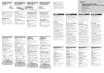
3-810-741-13(1) English Français Deutsch If it still persists... Features Powered Monitor Speaker System Operating Instructions Mode d'emploi Bedienungsanleitung • Professional quality inputs with high handling capacity (Balanced terminal +22 dB, Standard and Pin terminals +8 dB). • Allows mixing of two different input sources. • Magnetically shielded design allows placement near display monitors, TVs, etc. • Full range speaker and wood cabinet designed for high fidelity. • Beautiful front panel finished in synthetic marble. This speaker was designed as a reference for use in recording studios to provide an accurate reproduction of the mix balance. In order to convey the full realistic expression and power of the artist while maintaining a supreme musical charm, we've carefully considered each of the individual parts as well as every inch of the circuit board. We are confident you’ll enjoy this unique speaker both in and out of the studio. Cautions regarding usage • Be sure to turn the volume to “0” when switching the power of the input source on and off. • Remove the protective cover after you have connected the speaker and placed it in its final position. Check that there is no other source of magnetism* near the TV set. Any other source of magnetism can cause color irregularity due to an interaction with the speaker. * Examples of sources of magnetism: Rack, magnets attached to secure the doors of the TV stand, health tools, magnets used with a toy, etc. On installation • Do not install the speaker near heat sources such as radiators or air ducts, or in a place subject to direct sunlight, excessive dust, mechanical vibration or shock. • Good ventilation is essential to prevent internal heat buildup in the speaker. Place the speaker in a location with adequate air circulation. Do not place the speaker on a soft surface or too close to a wall as this may obstruct the ventilation hole on the back. On cleaning the cabinet Clean the cabinet with a soft cloth lightly moistened with water. Do not use any type of abrasive pad, scouring powder or solvent such as alcohol or benzine. If you have any questions or problems concerning your speaker that is not covered in this manual, please consult your nearest Sony dealer. Speaker Connections and Placement Placement Be sure to remove the protective cover before using the speaker. SMS-1P Caractéristiques •Entrées de qualité professionnelle à tenue de puissance élevée (prise symétrique +22 dB, prises standard classiques et miniature +8 dB). •Mélange de deux sources différentes possible. •Blindage antimagnétique permettant l’installation à proximité d’un moniteur, téléviseur, etc. •Enceinte pleine gamme avec coffret en bois, conçue pour la haute fidélité. •Magnifique panneau frontal en marbre synthétique. Cette enceinte a été conçue comme enceinte de référence pour l’utilisation en studios d’enregistrement et assure une reproduction exacte de la balance de mélange. Afin de reproduire de manière réaliste toute l’expression et la puissance de l’artiste tout en conservant un charme musical extrême, chaque pièce et chaque centimètre du circuit ont été attentivement étudiés. Nous sommes sûrs que cette enceinte exceptionnelle fera votre joie au studio ou chez vous. Précautions d’utilisation • Veillez à régler le volume sur “0” avant la mise sous ou hors tension de la source, d’entree. • Enlevez le panneau de protection seulement après avoir raccordé l’enceinte et l’avoir placée dans sa position définitive. • The speaker can be placed vertically or horizontally. • Two of these speakers placed sideways will fit into an EIA 3U size rack. • When installing the speaker(s) on a stand or rack, use the nuts located in the bottom of the speaker. (Compatible with pitch 60 mm or M5 screws.) OR P WE SPEA Ne pas oublier d’enlever le panneau de protection avant d’utiliser l’enceinte. The model and serial numbers are located on the rear of the unit. Record the serial number in the space provided below. Refer to them whenever you call upon your Sony dealer regarding this product. Model No. SMS–1P Serial No. For the customers in Canada S KER WE PO POWER ATTENTION This symbol is intended to alert the user to the presence of uninsulated “dangerous voltage” within the product’s enclosure that may be of sufficient magnitude to constitute a risk of electric shock to persons. POUR PREVENIR LES CHOCS ELECTRIQUES, NE PAS UTILISER CETTE FICHE POLARISSE AVEC UN PROLONGATEUR, UNE PRISE DE COURANT OU UNE AUTRE SORTIE DE COURANT, SAUF SI LES LAMES PEUVENT ETRE INSEREES A FOND SANS EN LAISSER AUCUNE PARTIE A DECOUVERT. OR NIT P MO RD SMS-1 KER SPEA Pour tout problème ou toute question au sujet de l’enceinte, non couverts dans ce manuel, veuillez consulter votre revendeur Sony. Position et raccordement de l’enceinte Sicherheitshinweise zum Betrieb • Stellen Sie beim Ein- und Ausschalten der Eingangsquelle stets den Lautstärkepegel auf 0. • Nachdem Sie den Lautsprecher angeschlossen und an den vorgesehenen Ort gestellt haben, nehmen Sie die Schutzabdeckung ab. Vor Verwendung des Lautsprechers die Schutzabdeckung abnehmen. • L’enceinte peut être installée à la verticale ou à l’horizontale. • Deux enceintes de ce type rentrent dans un rack de dimensions EIA 3U. • Lorsque vous installez l’enceinte (ou deux enceintes) dans un meuble ou un rack, utilisez les écrous se trouvant sous l’enceinte. (Compatibles avec un pas de vis de 60 mm ou des vis M5.) Wenn danach die Farben immer noch beeinträchtigt sind... Stellen Sie den Lautsprecher weiter vom TVGerät entfernt auf. Wenn auch dann das Problem noch nicht behoben ist... Überprüfen Sie, ob sich noch ein anderes Gerät etc., von dem Magnetfelder ausgehen*, in der Nähe des TV-Geräts befindet. Bedenken Sie, daß sich die Magnetfelder gegenseitig beeinflussen und verstärken können. * Magnetfelder gehen beispielsweise aus von: Metallgestellen, Magnetverschlüssen an Türen eines TV-Ständers, medizinischen Geräten und Spielzeug. Zur Aufstellung • Stellen Sie den Lautsprecher nicht in die Nähe von Wärmequellen wie Heizung oder Warmluftauslässen und auch nicht an Plätze, die direktem Sonnenlicht, starker Staubentwicklung, mechanischen Vibrationen oder Stößen ausgesetzt sind. • Stellen Sie den Lautsprecher so auf, daß ausreichende Luftzirkulation gewährleistet ist, damit es nicht zu einem internen Hitzestau kommt. Stellen Sie den Lautsprecher nicht auf eine weiche Unterlage und auch nicht zu dicht an die Wand, da sonst die Ventilationsöffnungen blockiert werden können. Zur Reinigung des Gehäuses Reinigen Sie das Gehäuse mit einem weichen, leicht mit Wasser angefeuchteten Tuch. Scheuerschwämme, Scheuerpulver und Lösungsmittel wie Alkohol oder Benzin dürfen nicht verwendet werden. Bei weiterführenden Fragen wenden Sie sich bitte an den nächsten Sony Händler. Anschluß und Aufstellung des Lautsprechers S Aufstellung OR P PO WE SPEA KER NIT MO RD SMS-1 Raccordements OFF Ne pas oublier de régler l’interrupteur POWER sur le panneau arrière sur OFF avant de raccorder l’enceinte. • Der Lautsprecher kann wahlweise vertikal oder horizontal aufgestellt werden. • In ein 3U-EIA-Gestell passen zwei Lautsprecher nebeneinander. • Bei Aufstellung des Lautsprechers auf einem Ständer oder in einem Gestell befestigen Sie ihn an der Unterseite mit M5-Schrauben (Gewindesteigung 60 mm). Anschluß • When listening at large volumes, we reccomend keeping the sound at a level where it does not distort. • Do not take apart or modify the enclosure, it may damage the speaker. • When moving the speaker, be sure to attach the supplied protective cover. AC IN CH 2 IN CH 1 IN To a wall outlet • Lorsque vous écoutez à volume élevé, veillez à régler le timbre de sorte qu’aucune distorsion n’apparaisse. • Ne pas démonter ou modifier le caisson pour ne pas endommager l’enceinte. • Quand vous changez l’enceinte de place, veillez à mettre le panneau de protection. • Stellen Sie die Lautstärke nur so hoch ein, daß keine Verzerrungen auftreten. • Nehmen Sie das Gehäuse nicht auseinander und modifizieren Sie es nicht, da es sonst beschädigt werden kann. • Beim Transport bringen Sie die mitgelieferte Schutzabdeckung wieder an. POWER ON OFF Stellen Sie den POWER-Schalter an der Rückseite auf OFF, bevor Sie Anschlüsse vornehmen. POWER ON OFF Audio pin cord Precautions Standard plug cord AC IN Précautions CH 2 IN CH 1 IN On safety • Do not attempt to open the enclosure or modify the speaker unit. • Before operating the speaker, be sure that the operating voltage of your speaker is identical with that of your local power supply. • Unplug the speaker from the wall outlet if it is not to be used for an extended period of time. To disconnect the cord, pull the cord by grasping the plug. Never pull the cord itself. • Should any liquid or solid object fall into the speaker, unplug the speaker and have the speaker checked by qualified personnel before operating it any further. • AC power cord must be changed only at the qualified service shop. This symbol is intended to alert the user to the presence of important operating and maintenance (servicing) instructions in the literature accompanying the appliance. When turning on or off other equipment CAUTION In case color irregularity is observed on the nearby TV screen You are cautioned that any changes or modification not expressly approved in this manual could void your authority to operate this equipment. Nettoyage du coffret Der SMS-1P ist dank der Mischmöglichkeit und der natürlichen Klangreproduktion ein idealer Monitorlautsprecher für Aufnahmestudios. Die mechanischen und elektrischen Bauteile dieser Box wurden mit größter Sorgfalt so ausgelegt, daß die Stimme des Künstlers und die Begleitmusik in allen Nuancierungen unverfälscht übertragen wird. Überall dort, wo es auf hohe Klangneutralität ankommt, ist der SMS-1P ist ein idealer Lautsprecher. ON CAUTION TO PREVENT ELECTRIC SHOCK, DO NOT USE THIS POLARIZED AC PLUG WITH AN EXTENSION CORD, RECEPTACLE OR OTHER OUTLET UNLESS THE BLADES CAN BE FULLY INSERTED TO PREVENT BLADE EXPOSURE. Installation • Ne pas installer l’enceinte près d’une source de chaleur, comme un radiateur ou un conduit d’air, ou dans un endroit exposé à la lumière directe du soleil, à une poussière excessive, à des vibrations mécaniques ou à des chocs. • Une bonne ventilation est essentielle pour éviter toute surchauffe interne de l’enceinte. Installez l’enceinte dans un endroit où la circulation de l’air est suffisante. Ne la posez pas sur une surface molle ou trop près d’un mur afin de ne pas obstruer l’orifice de ventilation à l’arrière de l’enceinte. • Verschiedenartige Eingangsbuchsen (symmetrische Buchse (+22 dB), Klinkenbuchse und Minibuchse (+8 dB)). • Zwei verschiedene Eingangsquellen können gemischt werden. • Dank magnetischer Abschirmung kann der Lautsprecher auch direkt neben ein TV-Gerät, einen Monitor usw. aufgestellt werden. • Breitbandchassis in Holzgehäuse für höchtsmögliche Klangqualität. • Ansprechende Frontplatte mit Marmormusterung. Position NIT MO RD SMS-1 Owner’s record Vérifiez s’il n’y a pas une autre source de magnétisme* près du téléviseur. Toute source de magnétisme peut causer des anomalies de couleurs par interaction avec l’enceinte. * Exemples de sources de magnétisme: Rack, aimants de portes de meuble de téléviseur, appareils paramédicaux, aimants sur des jouets, etc. Nettoyez le coffret avec un chiffon doux légèrement imprégné d’eau. Ne pas utiliser de tampons abrasifs, de poudre récurante ni de solvant, comme l’alcool ou la benzine. Be sure to set the POWER switch on the back panel to OFF before making any connections. PO Besondere Merkmale S’il n’y a aucune amélioration... Connections To prevent fire or shock hazard, do not expose the unit to rain or moisture. Eloignez les enceintes du téléviseur. S Sony Corporation 1996 Printed in China WARNING Si vous observez encore des anomalies... Lower the volume of the speaker to minimum. With the magnetically shielded type of the speaker system, the speakers can be installed near a TV set. However, color irregularity may still be observed on the TV screen depending on the type of your TV set. If color irregularity is observed... Turn off the TV set once, then turn it on after 15 to 30 minutes. If color irregularity is observed again... Place the speakers further apart from the TV set. Balanced (XLR) cord To the output terminals of an electronic instrument, mixing console, computer, or audio device (etc.). Balanced terminal polarity 1 : GND 2 : HOT 3 : COLD 2 3 1 Notes • We reccomend not connecting more than one sound source to each channel. • Use a commercially available adapter plug if you wish to reverse the HOT and COLD polarity of the balanced terminal. • Pass high impedance sources (like electric guitars) and low impedance sources (like microphones) through a mixer before connecting to the speaker. vers une prise murale Sécurité • Ne pas essayer d’ouvrir le caisson ni de modifier le haut-parleur. • Avant d’utiliser l’enceinte, assurez-vous que sa tension de fonctionnement est identique à celle de l’alimentation secteur locale. • Débranchez l’enceinte de la prise murale si vous prévoyez de ne pas l’utiliser pendant longtemps. Pour débrancher le cordon, tirez sur la fiche. Ne jamais tirer sur le cordon proprement dit. • Si un liquide ou un solide tombait dans l’enceinte, débranchez l’enceinte et faites-la vérifier par un professionnel avant de la remettre en service. • Le cordon d’alimentation secteur doit être changé par un professionnel. Cordon audio à fiche miniature Cordon à fiche standard Cordon à fiche symétrique (XLR) Aux prises de sortie d’un instrument électronique, console de mixage, ordinateur ou appareil audio (etc.) Polarité de la prise symétrique Avant de mettre un appareil sous ou hors tension 1 : GND 2 : HOT 3 : COLD Réduisez complètement le volume de l’enceinte. Si des anomalies de couleur apparaissent sur l’écran du téléviseur à proximité de l’enceinte Ayant un blindage magnétique, l’enceinte peut être normalement installée près d’un téléviseur. Cependant, avec certains téléviseurs, vous pouvez observer des anomalies de couleurs. Si vous observez des anomalies de couleurs... Eteignez le téléviseur puis remettez-le sous tension 15 à 30 minutes plus tard. 2 3 1 Remarques • Il est conseillé de ne pas raccorder plus d’une source à chaque canal. • Utilisez un adaptateur si vous voulez inverser la polarité HOT (chaud) et COLD (froid) de la prise symétrique. • Raccordez les sources à impédance élevée (guitares électriques) et celles à basse impédance (microphones) à un mixeur avant de les raccorder à l’enceinte. Zur besonderen Beachtung AC IN CH 2 IN CH 1 IN Zur Sicherheit • Versuchen Sie nicht, das Gehäuse zu öffnen oder zu modifizieren. • Vergewissern Sie sich vor dem Betrieb des Lautsprechers, daß die Betriebsspannung mit der örtlichen Netzspannung übereinstimmt. • Trennen Sie den Lautsprecher von der Wandsteckdose ab, wenn er längere Zeit nicht verwendet wird. Zum Abziehen des Kabels fassen Sie stets am Stecker und niemals am Kabel selbst an. • Sollte Flüssigkeit oder ein fester Gegenstand in den Lautsprecher gelangen, trennen Sie ihn ab und lassen Sie ihn von einem Fachmann überprüfen, bevor Sie ihn weiterverwenden. • Das Netzkabel darf nur von einer Fachwerkstatt ausgewechselt werden. Ministecker Klinkenstecker Symmetrischer XLR-Stecker Anschlußkabel für elektrisches Musikinstrument, Mischkonsole, Computer, Audiogerät usw. Belegung der symmetrischen XLR-Buchse Beim Ein- und Ausschalten der Signalquelle 1 : GND 2 : HOT 3 : COLD Stellen Sie die Lautstärke auf den Minimalpegel Wenn es durch den Lautsprecher zu Farbbeeinträchtigungen auf einem TV-Monitor kommt Dank seiner magnetischen Abschirmung kann der Lautsprecher normalerweise problemlos direkt neben ein TV-Gerät gestellt werden. Sollte es bei bestimmten TV-Geräten dennoch einmal zu Farbbeeinträchtigungen kommen, verfahren Sie wie folgt: Bei Farbbeeinträchtigungen... Schalten Sie das TV-Gerät einmal aus und dann nach 15 bis 30 Minuten wieder ein. An eine Wandsteckdose 2 3 1 Hinweise • Schließen Sie an jedem Kanal nur eine Signalquelle an. • Falls erforderlich, kann Phase (HOT) und Erde (COLD) des symmetrischen XLR-Anschlusses mit einem handelsüblichen Adapter vertauscht werden. • Schließen Sie Signalquellen hoher Impedanz (Elektrogitarre usw.) und niedriger Impedanz (Mikrofon usw.) über einen Mischer an den Lautsprecher an. English Français Deutsch 3 Names and Functions of Parts 4 Front CH 2 IN Standard terminal Standard input terminal for channel 2. Connect to the output terminal of an electronic instrument (etc.). 5 CH 1 IN Standard terminal Standard input terminal for channel 1. Connect to the output terminal of an electronic instrument (etc.). 6 CH 1 IN Pin plug terminal Pin plug input terminal for channel 1. Connect to the output terminal of an audio component (etc.). Nomenclature Avant 4 5 S 6 POWER MONITOR SPEAKER SYSTEM SMS-1P S Specifications POWER MONITOR SPEAKER SYSTEM SMS-1P POWER BASS – 1 1 2 3 4 TREBLE + 2 – + 3 VOL. CH 1 0 10 POWER – VOL. CH 2 0 AUDIO POWER SPECIFICATIONS POWER OUTPUT AND TOTAL HARMONIC DISTORTION: With 4 ohm load driven, from 40 Hz - 20 kHz; rated 14 watts minimum RMS power, with more than 0.9 % total harmonic distortion from 250 mW to rated output. 10 4 POWER indicator Lights when the POWER switch is set to the ON position. BASS knob Turn to the right to increase the level of the bass. Turn to the left to decrease the level of the bass. (Increasing the level of the bass when listening at high volumes may cause the sound to distort.) TREBLE knob Turn to the right to increase the level of the treble. Turn to the left to decrease the level of the treble. VOL. (volume) CH 1 and CH 2 knobs Turning the VOL. CH 1 or VOL. CH 2 knob to the right increases the volume of the source connected to the respective input. If nothing is connected to one of the input terminals, set the respective knob to the “0” position. These knobs can also be used to adjust the mix balance of sound sources connected to CH 1 and CH 2. Rear POWER ON OFF BASS 1 1 1 Speaker Speaker system Full range bass reflex Speaker unit 10 cm (315⁄16 inches) dia. cone type Nominal Impedance 4 ohms Power handling capacity Nominal 25 W Maximum 50 W Sensitivity 88 dB/W/m Frequency range 80 Hz - 16 kHz (– 10 dB) Enclosure volume Approx. 3.2 liters Amplifier Output 15 W Inputs CHANNEL 1 Pin jack x 1 Standard jack x 1 CHANNEL 2 Balanced terminal x 1 Standard jack x 1 Input level Balanced terminal : + 4 dB Standard jack : – 10 dB Pin jack : – 10 dB Input impedance Balanced terminal : 600 ohms Standard jack : 10 kilohms Pin jack : 10 kilohms Tone controls BASS 100 Hz : ±6 dB TREBLE 10 kHz : ±6 dB 2 3 4 TREBLE + 2 – + VOL. CH 1 0 10 3 VOL. CH 2 0 10 Indicateur d’alimentation (POWER) Il s’allume quand l’interrupteur POWER est réglé sur la position ON. AC IN Bouton de réglage du grave (BASS) Tournez le bouton vers la droite pour augmenter le niveau du grave et vers la gauche pour le réduire. (Une trop forte augmentation du grave lors de l’écoute à volume élevé peut causer de la distorsion.) Bouton de réglage de l’aigu (TREBLE) Tournez le bouton vers la droite pour augmenter le niveau de l’aigu et vers la gauche pour le réduire. Boutons de réglage du volume des canaux 1 et 2 (VOL. CH 1 et VOL. CH 2) Tournez les boutons VOL. CH 1 ou VOL. CH 2 vers la droite pour augmenter le volume de la source raccordée à l’entrée correspondante. Si rien n’est raccordé à l’une des prises d’entrée, réglez le bouton correspondant sur la position “0”. Ces boutons peuvent aussi être utilisés pour équilibrer le mélange de sources sonores raccordées à CH 1 et CH 2. Arrière 3 2 3 AC socket Connect to a wall outlet (120 V in U.S.A. or Canada, 220-230 V in Europe) using the supplied power cord. CH 2 IN Balanced terminal Balanced input terminal for channel 2. Connect to the output terminal of a professional mixing console (etc.). CH 1 IN-Minibuchse Diese Minibuchse von Kanal 1 dient zum Anschluß von Signalquellen wie elektronische Musikinstrumente usw. POWER MONITOR SPEAKER SYSTEM SMS-1P POWER BASS – 1 TREBLE + – + VOL. CH 1 VOL. CH 2 0 0 10 10 2 3 4 1 POWER-Anzeige Leuchtet auf, wenn der POWERSchalter eingeschaltet ist. 2 BASS-Regler Durch Drehen nach rechts werden die Bässe angehoben und durch Drehen nach links verringert. (Bei hoher Lautstärke kann die Baßanhebung zu Verzerrungen führen.) 3 4 TREBLE-Regler Durch Drehen nach rechts werden die Höhen angehoben und durch Drehen nach links abgesenkt. VOL.CH 1- und CH 2-Regler Durch Drehen nach rechts wird der Pegel des betreffenden Kanals erhöht. Wenn an einem Kanal keine Signalquelle angeschlossen ist, stellen Sie den Regler auf 0. Darüber hinaus kann mit diesen Reglern auch die Mischbalance der an CH 1 und CH 2 angeschlossenen Signalquellen eingestellt werden. Rückseite General Dimensions Approx. 132 × 210 × 230 mm (w/h/d) (53⁄16 × 81⁄4 × 91⁄16 inches) excluding projecting parts and controls Mass Approx. 3.3 kg (7 lb 4 oz) Supplied accessories Power cord (1) Protector (1) 1 2 AC IN Design and specifications are subject to change without notice. ON OFF Dimensions hors tout Env. 132 x 210 x 230 mm (l/h/p) (53⁄16 × 81⁄4 × 91⁄16 pouces) Poids Environ 3,3 kg (7 li. 4 on) Accessoires fournis Cordon d’alimentation (1) Protection (1) 1 2 AC IN CH 2 IN CH 1 IN La conception et les spécifications peuvent être modifiées sans préavis. 3 CH 2 IN 4 5 6 CH 1 IN 1 1 POWER-Schalter Mit diesem Schalter wird der Lautsprecher eingeschaltet (ON) bzw. ausgeschaltet (OFF). Stellen Sie vor dem Einschalten stets den VOL. CH 1- und VOL. CH 2-Regler auf 0. 2 AC-Anschluß Das mitgelieferte Netzkabel an dieser Buchse und an einer Wandsteckdose (USA und Kanada: 120 V, Europa: 220230 V) anschließen. 2 3 Symmetrische CH 2 IN-Buchse Diese symmetrische Eingangsbuchse von Kanal 2 dient zum Anschluß von Profigeräten (Mischkonsole usw.). 4 5 6 Interrupteur d’alimentation (POWER) Pour mettre l’enceinte sous ou hors tension (ON/OFF). (Avant de la mettre sous tension, veillez à régler les deux boutons VOL. CH 1 et VOL. CH 2 sur la position “0”.) Prise secteur (AC) Reliez cette prise à une prise murale (120 V Etats-Unis et Canada, 220-230 V Europe) à l’aide du cordon secteur fourni. Output sound pressure, Frequency characteristics / adjustable range of tone controls Niveau de pression sonore, caractéristiques des fréquences/ plage de réglage des commandes du timbre Schalldruckpegel und Einfluß der Klangregler auf den Frequenzgang 100 90 HI MAX 80 FLAT 60 1 HI MIN FLAT 50 Lautsprecher 40 System Breitbandtyp, Baßreflex Bestückung Konus-Lautsprecherchassis mit 10 cm Durchmesser Nennimpedanz 4 Ohm Nennbelastbarkeit 25 W Max. Belastbarkeit 50 W Kennschalldruckpegel 88 dB/W/m Frequenzgang 80 Hz - 16 kHz (– 10 dB) Gehäusevolumen ca. 3,2 Liter 30 LOW MIN 20 10 0 20 50 100 200 500 Ausgangsleistung 15 W Eingänge Kanal 1 (CH1) Minibuchse x 1 Klinkenbuchse x 1 Kanal 2 (CH2) Symmetrische Buchse x 1 Klinkenbuchse x 1 Eingangspegel Symmetrische Buchse: +4 dB Klinkenbuchse: – 10 dB Minibuchse: – 10 dB Eingangsimpedanz Symmetrische Buchse: 600 Ohm Klinkenbuchse: 10 kOhm Minibuchse: 10 kOhm Klangregler BASS: ±6 dB bei 100 Hz TREBLE: ±6 dB bei 10 kHz Abmessungen ca. 132 x 210 x 230 mm (B/H/T), ausschl. vorspringender Teile und Bedienungselemente Gewicht ca. 3,3 kg Mitgeliefertes Zubehör Netzkabel (1) Schutzabdeckung (1) Änderungen, die dem technischen Fortschritt dienen, bleiben vorbehalten. 1K 2K 2 1 2 Output sound pressure level (dB) Frequency (Hz) Input : Pin Jack (– 30 dB) Volume : VOL. CH 1 max Anechoic room : 1 meter Verstärker Allgemeines POWER 4 5 6 POWER switch Turns the power to the speaker ON/ OFF. (Before turning the power ON, be sure the VOL. CH 1 and VOL. CH 2 knobs are set to the “0” position.) 6 Technische Daten S Spécifications Sortie 15 W Entrées CHANNEL 1 Prise miniature x 1 Prise standard x 1 CHANNEL 2 Prise symétrique x 1 Prise standard x 1 Niveau d’entrée Prise symétrique: + 4dB Prise standard: – 10 dB Prise miniature: – 10 dB Impédance d’entrée Prise symétrique: 600 ohms Prise standard: 10 kohms Prise miniature: 10 kohms Commandes du timbre BASS 100 Hz : ±6 dB TREBLE 10 kHz : ±6 dB CH 1 IN-Klinkenbuchse Diese Klinkenbuchse von Kanal 1 dient zum Anschluß von Signalquellen wie elektronische Musikinstrumente usw. LOW MAX Prise pour fiche miniature (CH 1 IN) Prise d’entrée de fiche miniature pour le canal 1. Reliez la prise de sortie d’un appareil audio, par exemple, à cette prise. Amplificateur 5 70 Généralités ON 3 1 Prise standard (CH 1 IN) Prise d’entrée standard pour le canal 1. Reliez la prise de sortie d’un instrument électronique, par exemple, à cette prise. Système d’enceinte Bass-reflex pleine gamme Haut-parleur 10 cm (315⁄16 pouces) à cône Impédance nominale 4 ohms Tenue en puissance Nominale 25 W Maximum 50 W Sensibilité 88 dB/W/m Plage de fréquences 80 Hz - 16 kHz (– 10 dB) Volume de l’enceinte Environ 3,2 litres CH 2 IN-Klinkenbuchse Diese Klinkenbuchse von Kanal 2 dient zum Anschluß von Signalquellen wie elektronische Musikinstrumente usw. POWER CH 2 IN CH 1 IN Vorderseite Prise standard (CH 2 IN) Prise d’entrée standard pour le canal 2. Reliez la prise de sortie d’un instrument électronique, par exemple, à cette prise. Enceinte 4 Bezeichnung der Bedienungselemente 4 OFF 2 Prise symétrique (CH 2 IN) C’est la prise d’entrée symétrique pour le canal 2. Reliez la prise de sortie d’une console de mixage professionnelle, par exemple, à cette prise. Characteristic data Données caractéristiques Kenndiagramm 1 2 Niveau de pression sonore (dB) Fréquence (Hz) Entrée: Prise miniature (– 30 dB) Volume: VOL. CH 1 maximum Chambre anéchoïque: 1 mètre 1 2 Schalldruckpegel (dB) Frequenz (Hz) Eingang: Minibuchse (– 30 dB) Lautstärke: VOL. CH 1-Regler auf max. Schalltoter Raum: 1 m 5K 10K 20K 50K