1
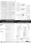
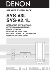
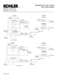
3-858-673-12(1)
Powered Monitor
Speaker System
Operationg Instructions
EN
Mode d’emploi
F
Bedienungsanleitung
D
SMS-2P
©1997 by Sony Corporation
WARNING
To prevent fire or shock hazard, do not
expose the unit to rain or moisture.
To avoid electrical shock, do not open the cabinet.
Refer servicing to qualified personnel only.
Do not install the appliance in a confined space,
such as a bookcase or buitl-in cabinet because
the mains power switch (MAIN POWER) is
located on the rear exterior.
NOTICE FOR THE CUSTOMERS IN THE
U.S.A.
This symbol is intended to alert the
user to the presence of uninsulated
“dangerous voltage” within the
product’s enclosure that may be of
sufficient magnitude to constitute a
risk of electric shock to persons.
This symbol is intended to alert the
user to the presence of important
operating and maintenance (servicing)
instructions in the literature
accompanying the appliance.
CAUTION
You are cautioned that any changes or modification
not expressly approved in this manual could void
your authority to operate this equipment.
Owner’s record
The model and serial numbers are located on
the rear of the unit. Record the serial number
in the space provided below. Refer to them
whenever you call upon your Sony dealer
regarding this product.
Model No. SMS–2P
Serial No.
2
NOTICE FOR THE CUSTOMERS IN
CANADA
CAUTION:
TO PREVENT ELECTRIC SHOCK, DO NOT USE
THIS POLARIZED AC PLUG WITH AN
EXTENSION CORD,
RECEPTACLE OR OTHER OUTLET UNLESS THE
BLADES CAN BE FULLY INSERTED TO PREVENT
BLADE EXPOSURE.
Table of Contents
Precautions .............................................. 4
Speaker connections and placement ... 5
Names and Functions of parts .............. 6
Specifications .......................................... 8
Characteristic data .................................. 9
Features
• Professional quality inputs with high
handling capacity (Balanced terminal +24
dB, phone and phono terminals +10 dB).
• Allows mixing of two different input
sources.
• Magnetically shielded design allows
placement near display monitors, TVs, etc.
• 2 way speaker and wood cabinet designed
for high fidelity.
• Use of sandwich construction in baffle
board damping.
• Up to 20 of these speakers can be
connected via cascade connections.
This speaker was designed as a reference for
use in recording studios to provide an
accurate reproduction of the mix balance. In
order to convey the full realistic expression
and power of the artist while maintaining a
supreme musical charm, we've carefully
considered each of the individual parts as
well as every inch of the circuit board.
EN
We are confident you’ll enjoy this unique
speaker both in and out of the studio.
3
Precautions
• Remove the protective cover after you have
connected the speaker and placed it in its
final position.
• When listening at large volumes, we
recommend keeping the sound at a level
where it does not distort.
• To prevent damage to the speaker unit, be
sure to attatch the supplied protective
cover when moving the speaker or placing
it in storage.
on safety
• Do not attempt to open the enclosure or
modify the speaker unit.
• Before operating the speaker, be sure that
the operating voltage of your speaker is
identical with that of your local power
supply.
• Unplug the speaker from the wall outlet if
it is not to be used for an extended period
of time. To disconnect the cord, pull the
cord by grasping the plug. Never pull the
cord itself.
• Should any liquid or solid object fall into
the speaker, unplug the speaker and have
the speaker checked by qualified personnel
before operating it any further.
• AC power cord must be changed only at
the qualified service shop.
When turning on or off other
equipment
Lower the volume of the speaker to
minimum.
In case color irregularity is
observed on the nearby TV screen
With the magnetically shielded type of the
speaker system, the speakers can be installed
near a TV set. However, color irregularity
may still be observed on the TV screen
depending on the type of your TV set.
If color irregularity is observed...
Turn off the TV set once, then turn it on after
15 to 30 minutes.
If color irregularity is observed again...
Place the speakers further apart from the TV
set.
4
If it still persists...
Check that there is no other source of
magnetism* near the TV set. Any other source
of magnetism can cause color irregularity due
to an interaction with the speaker.
* Examples of sources of magnetism: Rack,
magnets attached to secure the doors of the
TV stand, health tools, magnets used with
a toy, etc.
On installation
• Do not install the speaker near heat sources
such as radiators or air ducts, or in a place
subject to direct sunlight, excessive dust,
mechanical vibration or shock.
• Good ventilation is essential to prevent
internal heat buildup in the speaker. Place
the speaker in a location with adequate air
circulation. Do not place the speaker on a
soft surface or too close to a wall as this
may obstruct the ventilation hole on the
back.
On cleaning the cabinet
Clean the cabinet with a soft cloth lightly
moistened with water. Do not use any type
of abrasive pad, scouring powder or solvent
such as alcohol or benzine.
If you have any questions or problems
concerning your speaker that is not covered
in this manual, please consult your nearest
Sony dealer.
Speaker Connections
and Placement
Placement
The speaker can be placed vertically or
horizontally.
Connections
Be sure to set the POWER switch on the back
panel to OFF before making any connections.
TW LEVEL
NORMAL
–
MASTER VOL.
+
0
10
BASS
–
–
• We reccomend not connecting more than one
sound source to each channel.
• The RETURN terminal should only be used to
input the sound output from the SEND terminal
(after looping it through an effector, etc.) or when
connecting several speakers. Connections made to
the RETURN terminal for other purposes will not
allow the sound input to the CH1 and CH2
terminals to be output.
• Pass high impedance sources (like electric guitars)
and low level sources (like microphones) through
a mixer before connecting to the speaker.
To connect several speakers
Be sure to set the POWER switch on the back
panel to OFF before making any connections.
Connect the CASCADE OUT terminal on the
first speaker to the RETURN terminal on the
second speaker, etc. (You can connect up to
20 speakers.)
TREBLE
+
Notes
+
CH 1 IN
VOL
SEND
3HOT 2HOT
0
10
CH 2 IN
Connect only one.
VOL
CASCADE
OUT
RETURN
CH IN
0
3HOT 2HOT
DIRECT
10
Balanced(XLR)cord
phone plug cord
TW LEVEL
NORMAL
–
ON
0
10
BASS
–
TW LEVEL
NORMAL
TREBLE
+
–
–
+
MASTER VOL.
+
0
10
BASS
–
TREBLE
+
–
+
CH 1 IN
CH 1 IN
VOL
VOL
SEND
3HOT 2HOT
3HOT 2HOT
0
0
10
10
CH 2 IN
CH 2 IN
VOL
VOL
CASCADE
OUT
RETURN
CH IN
0
POWER
MASTER VOL.
+
SEND
3HOT 2HOT
DIRECT
CASCADE
OUT
RETURN
CH IN
0
10
3HOT 2HOT
DIRECT
10
Audio phono cord
POWER
POWER
ON
ON
BREAKER
BREAKER
BREAKER
OFF
OFF
OFF
To the output
terminals of an
electronic
instrument,
mixing console,
computer, or
audio device
(etc.).
AC IN
To a wall
outlet
AC IN
First
Speaker
To the RETURN
terminal on the
next speaker.
AC IN
Second
Speaker
How to use the slip stoppers
This unit comes
supplied
Balanced
(XLR)with
cord 4 round (15
mm diameter) slip stoppers. Attach one
under each of the speaker's four corners to
prevent the speaker from moving when
subject to slight vibrations (etc.).
Balanced terminal polarity
When the balanced
input terminal
polarity switch is set
to 2HOT.
When the balanced
input terminal
polarity switch is set
to 3HOT.
1 : GND
2 : HOT
3 : COLD
2
3
1
1 : GND
2 : COLD
3 : HOT
2
3 1
5
Names and Functions
of Parts
Rear
1
2
3
TW LEVEL
NORMAL
–
MASTER VOL.
+
0
10
BASS
–
TREBLE
+
–
+
CH 1 IN
VOL
SEND
3HOT 2HOT
0
10
CH 2 IN
VOL
CASCADE
OUT
RETURN
CH IN
0
3HOT 2HOT
DIRECT
10
4
5
6
7
8
POWER
ON
BREAKER
9
OFF
AC IN
10
11
12
13
1 SEND terminal
Outputs a mix of the sounds input to
channel 1 and channel 2. Connect to an
effector or recording device (etc.). The
sound is output as adjusted by the BASS
and TREBLE.
2 TW LEVEL control
Adjusts the output level of the tweeter.
Turn toward the right to increase. Turn
toward the left to decrease.
3 MASTER VOL. (volume) control
Turning to the right increases the level of
the sound output from the speaker.
4 Bass control
6
Turn to the right to increase the level of the
bass. Turn to the left to decrease the level
of the bass. (Increasing the level of the bass
when listening at high volumes may cause
the sound to distort.)
5 TREBLE control
Turn to the right to increase the level of the
treble. Turn to the left to decrease the level
of the treble.
6 CH 1 IN (channel 1 input)
See next page for details.
7 CH 2 IN (channel 2 input)
See next page for details.
8 Rear panel guards
Protect the controls on the rear of the
speaker. Located on the left and right.
9 POWER switch
Turns the power to the speaker ON/OFF.
(Before turning the power ON, be sure the
MASTER VOL. control is set to the “0”
position.)
10 AC socket
Connect to a wall outlet (120 V in U.S.A. or
Canada, 220-230 V in Europe) using the
supplied power cord.
11 BREAKER
Press if the pilot lamp on the front panel
does not light when the power is turned
on. This resets the power supply so you
can use the speaker.
12 RETURN terminal
Use to input an external sound source
directly to the speaker’s power amp.
Use this terminal to input sound output to
an effector, or when connecting several
speakers.
13 CASCADE OUT terminal
Allows you to output a mix of the sounds
input to channel 1 and channel 2. Use to
output sound when connecting several
speakers.
4 DIRECT switch (Only for Balanced
CH 1 input
CH 1 IN
VOL
3HOT 2HOT
0
10
4
1 2 3
5
1 INPUT VOL. (channel 1 input level)
control
Turning to the right increases the level of
the sound output from the channnel 1
input terminal)
Setting this switch to DIRECT allows you
to bypass the tone controls and send the
sound from a mixer (etc.) directly to the
speaker's power amplifier. In this case,
BASS and TREBLE adjustments are not
possible. Only the MASTER VOL. and TW
LEVEL can be adjusted.
Note
When the DIRECT switch is set to DIRECT, no
sound will be output to the other speakers (if
other speakers are connected).
5 Balanced input terminal
2 Pin plug input terminal
Phono plug input terminal for channel 1.
Connect to the output on a piece of audio
equipment (etc.).
6 Balanced input terminal polarity
switch
3 Standard plug input terminal
phone plug input terminal for channel 1.
Connect to the output on a musical
instrument (etc.).
Front
4 Balanced input terminal
Balanced input terminal for channel 1.
Connect the the out put terminal of a
professionl mixing console (etc).
5 Balanced input terminal polarity
switch
Use to switch the polarity of the channel 1
balanced input terminal.
POWER
CH 2 input
CH 2 IN
VOL
CH IN
0
3HOT 2HOT
DIRECT
1
10
1 Power Indicator
1 2
3
4
5
6
1 INPUT VOLUME. (channel 2 input
Lights when the POWER switch is set to
the ON position.
level) control
2 Pin plug input terminal
3 Standard plug input terminal
7
Inputs
Specifications
AUDIO POWER SPECIFICATIONS
POWER OUTPUT AND TOTAL
HARMONIC DISTORTION:
With 6 ohm load driven, from 20 Hz 20 kHz; rated 40 watts minimum RMS
power, with more than 0.9 % total
harmonic distortion from 250 mW to
rated output.
CH 1
Phono jack x 1
phone jack x 1
XLR jack x 1
CH 2
Phono jack x 1
phone jack x 1
XLR jack x 1
OTHER
RETURN jack x 1
Input level
Phono jack : – 10 dBm
(+10dBm)
Phone jack : – 10 dBm
(+10dBm)
Balanced terminal : + 4
dBm
(+24dBm)
RETURN : 0 dBm
(+20dBm)
Speaker system
2 way bass reflex
Speaker unit
Woofer:
16 cm (6 5⁄16 inches) dia.
cone type
Tweeter:
2.5cm (1 inch) dia. dome
type
Input impedance
Phono jack : 10 kilohms
Phone jack : 10 kilohms
Balanced terminal : 600
ohms
Nominal Impedance
Woofer:
6 ohms
Tweeter:
6 ohms
Power handling capacity
Woofer:
50 W
Tweeter:
40 W
Sensitivity
107 dB/m
Frequency range
48 Hz - 20 kHz (± 3 dB)
Dimensions
Approx. 239 × 410 × 331
mm (w/h/d)
(9 7/16× 16 1⁄8 × 13 1⁄16
inches.)
excluding projecting
parts and
controls
Approx. 239 × 410× 365
mm (w/h/d)
(9 7⁄16 × 16 1⁄8 × 143⁄8
inches.)
Including projecting parts
and
controls
Enclosure volume
Approx. 14 liters
Mass
Approx. 13 kg (28 lb 10
oz) excluding protective
cover
Power requirements
North American models: 120 V AC, 60 Hz
Europian models:
220-230V AC, 50/60 Hz
Power consumption
44W
8
Output level
SEND jack : (0 dBm)
CASCADE jack : (as same
as RETURN level)
Tone controls
BASS 100 Hz : ±6 dB
TREBLE 10 kHz : ±6 dB
Tweeter level controls
+2.5 dB/-3.5dB
Supplied accessories
Power cord (1)
Protective cover (1)
Slip stoppers (4)
Instruction manual (1)
Design and specifications are subject to change
without notice.
Characteristic data
Frequency characteristics / adjustable range of tone controls
100
HI MAX
LOW MAX
90
FLAT
80
70
60
1
50
40
HI MIN
FLAT
LOW MIN
30
20
10
0
20
50
100
200
500
1K
2K
5K
10K
20K
50K
2
1 Output sound pressure level (dB)
Input : Phono Jack (– 30 dB)
2 Frequency (Hz)
Volume : VOL. CH 1 master, max
Anechoic room : 1 meter
Frequency characteristics / adjustable range of tweeter level controls
100
TW LEVEL MAX
90
FLAT
80
70
60
1
TW LEVEL MIN
50
40
30
20
10
0
20
50
100
200
500
1K
2K
5K
10K
20K
50K
2
1 Output sound pressure level (dB)
Input : Phono Jack (– 30 dB)
2 Frequency (Hz)
Volume : VOL. CH 1 master, max
Anechoic room : 1 meter
9
AVERTISSEMENT
Afin d’éviter tout risque
d’incendie ou
d’électrocution, ne pas
exposer cet appareil à la
pluie ou à l’humidité.
ATTENTION
POUR PREVENIR LES CHOCS
ELECTRIQUES, NE PAS UTILISER CETTE
FICHE POLARISSE AVEC UN
PROLONGATEUR, UNE PRISE DE
COURANT OU UNE AUTRE SORTIE DE
COURANT, SAUF SI LES LAMES PEUVENT
ETRE INSEREES A FOND SANS EN
LAISSER AUCUNE PARTIE A
DECOUVERT.
2
Table des matières
Précautions .............................................. 4
Position et raccordement de l’enceinte 5
Nomenclature ......................................... 6
Spécifications .......................................... 8
Données caractéristiques ....................... 9
Caractéristiques
• Entrées de qualité professionnelle à tenue
de puissance élevée (prise symétrique +24
dB, prises standard classiques et miniature
+10 dB).
• Mélange de deux sources différentes
possible.
• Blindage antimagnétique permettant
l’installation à proximité d’un moniteur,
téléviseur, etc.
• Enceinte à deux voies et coffret en bois,
conçue pour la haute fidélité.
• Matériau d’amortissement entre les parois
d’enceinte.
• Raccordement de 20 enceintes en cascade
possible.
Cette enceinte a été conçue comme enceinte
de référence pour l’utilisation en studios
d’enregistrement et assure une reproduction
exacte de la balance de mélange. Afin de
reproduire de manière réaliste toute
l’expression et la puissance de l’artiste tout en
conservant un charme musical extrême,
chaque pièce et chaque centimètre du circuit
ont été attentivement étudiés.
F
Nous sommes sûrs que cette enceinte
exceptionnelle fera votre joie au studio ou
chez vous.
3
Précautions
Précautions d’utilisation
• Enlevez le panneau de protection
seulement après avoir raccordé l’enceinte
et l’avoir placée dans sa position définitive.
• Lorsque vous écoutez à volume élevé,
veillez à régler le timbre de sorte
qu’aucune distorsion n’apparaisse.
• Veillez à fixer le panneau de protection
fourni pour ne pas endommager l’enceinte
lorsque vous la déplacez ou la rangez.
Sécurité
• Ne pas essayer d’ouvrir le caisson ni de
modifier le haut-parleur.
• Avant d’utiliser l’enceinte, assurez-vous
que sa tension de fonctionnement est
identique à celle de l’alimentation secteur
locale.
• Débranchez l’enceinte de la prise murale si
vous prévoyez de ne pas l’utiliser pendant
longtemps. Pour débrancher le cordon,
tirez sur la fiche. Ne jamais tirer sur le
cordon proprement dit.
• Si un liquide ou un solide tombe dans
l’enceinte, débranchez l’enceinte et faites-la
vérifier par un professionnel avant de la
remettre en service.
• Le cordon d’alimentation secteur doit être
changé par un professionnel.
Avant de mettre un appareil sous
ou hors tension
Réduisez complètement le volume de
l’enceinte.
Si des anomalies de couleur
apparaissent sur l’écran du
téléviseur à proximité de
l’enceinte
Ayant un blindage magnétique, l’enceinte
peut être normalement installée près d’un
téléviseur. Cependant, avec certains
téléviseurs, vous pouvez observer des
anomalies de couleurs.
Si vous observez des anomalies de
couleurs...
Eteignez le téléviseur puis remettez-le sous
tension 15 à 30 minutes plus tard.
4
Si vous observez encore des
anomalies...
Eloignez les enceintes du téléviseur.
S’il n’y a aucune amélioration...
Vérifiez s’il n’y a pas une autre source de
magnétisme* près du téléviseur. Toute source
de magnétisme peut causer des anomalies de
couleurs par interaction avec l’enceinte.
* Exemples de sources de magnétisme: Rack,
aimants de portes de meuble de téléviseur,
appareils paramédicaux, aimants sur des
jouets, etc.
Installation
• Ne pas installer l’enceinte près d’une
source de chaleur, comme un radiateur ou
un conduit d’air, ou dans un endroit
exposé à la lumière directe du soleil, à une
poussière excessive, à des vibrations
mécaniques ou à des chocs.
• Une bonne ventilation est essentielle pour
éviter toute surchauffe interne de
l’enceinte. Installez l’enceinte dans un
endroit où la circulation de l’air est
suffisante. Ne la posez pas sur une surface
molle ou trop près d’un mur afin de ne pas
obstruer l’orifice de ventilation à l’arrière
de l’enceinte.
Nettoyage du coffret
Nettoyez le coffret avec un chiffon doux
légèrement imprégné d’eau. Ne pas utiliser
de tampons abrasifs, de poudre récurante ni
de solvant, comme l’alcool ou la benzine.
Pour tout problème ou toute question au sujet
de l’enceinte, non couverts dans ce manuel,
veuillez consulter votre revendeur Sony.
Remarques
Position et
raccordement de
l’enceinte
Position
• L’enceinte peut être installée à la verticale
ou à l’horizontale.
• Il est conseillé de ne pas raccorder plus d’une
source à chaque canal.
• La prise RETURN ne doit être utilisée que pour
transmettre le son fourni par la prise SEND (après
passage dans un processeur d’essai, etc.) ou
lorsque vous raccordez plusieurs enceintes. Tout
autre raccordement à la prise RETURN ne
permettra pas de transmettre le son fourni aux
canaux 1 et 2.
• Raccordez les sources à impédance élevée
(guitares électriques) et celles à basse impédance
(microphones) à un mixeur avant de les raccorder
à l’enceinte.
Raccordements
Ne pas oublier de régler l’interrupteur
POWER sur le panneau arrière sur OFF avant
de raccorder l’enceinte.
TW LEVEL
NORMAL
–
MASTER VOL.
+
0
10
BASS
–
–
Veillez à régler l’interrupteur POWER à
l’arrière de l’enceinte sur OFF (arrêt) avant de
faire les raccordements.
Raccordez la prise CASCADE OUT de la
première enceinte à la prise RETURN de la
seconde enceinte, et ainsi de suite. (Vous
pouvez raccorder en tout 20 enceintes.)
TREBLE
+
Pour raccorder plusieurs enceintes
+
CH 1 IN
VOL
SEND
3HOT 2HOT
0
10
CH 2 IN
VOL
CASCADE
OUT
RETURN
CH IN
0
3HOT 2HOT
DIRECT
10
POWER
ON
BREAKER
OFF
AC IN
Raccordez-en un seul.
Cordon à fiche
symétrique (XLR)
Cordon à fiche
standard
Cordon audio à
fiche miniature
Aux prises de
sortie d’un
instrument
électronique,
console de
mixage,
ordinateur ou
appareil audio
(etc.)
vers une
prise murale
TW LEVEL
NORMAL
–
MASTER VOL.
+
0
10
BASS
–
TW LEVEL
NORMAL
TREBLE
+
–
–
+
MASTER VOL.
+
0
10
BASS
–
TREBLE
+
–
+
CH 1 IN
CH 1 IN
VOL
VOL
SEND
SEND
3HOT 2HOT
3HOT 2HOT
0
0
10
10
CH 2 IN
CH 2 IN
VOL
VOL
CASCADE
OUT
RETURN
CH IN
0
3HOT 2HOT
DIRECT
CASCADE
OUT
RETURN
CH IN
0
10
3HOT 2HOT
DIRECT
10
POWER
POWER
ON
ON
BREAKER
BREAKER
OFF
OFF
AC IN
AC IN
A la prise
RETURN de
l’enceinte
suivante
Première enceinte Secondes enceinte
Utilisation des tampons
Quatre tampons ronds de 15 mm de diamètre
sont fournis avec l’enceinte. Fixez-les dans
chaque coin du socle pour que l’enceinte ne
bouge pas quand elle est soumise à des
vibrations, ou autre choc.
Polarité de la prise symétrique
Quand le commutateur
de polarité de prise
d’entrée symétrique
est réglé sur 2: HOT.
Quand le commutateur
de polarité de prise
d’entrée symétrique
est réglé sur 3: HOT.
1 : GND
2 : HOT
3 : COLD
2 3 1
1 : GND
2 : COLD
3 : HOT
2 3 1
5
(Une trop forte augmentation du grave à
volume élevé peut causer de la distorsion.)
Nomenclature
5 Bouton de réglage de l’aigu
Arrière
1
2
TW LEVEL
NORMAL
–
MASTER VOL.
+
0
10
BASS
–
TREBLE
+
–
+
CH 1 IN
VOL
SEND
3HOT 2HOT
0
10
CH 2 IN
VOL
CASCADE
OUT
RETURN
CH IN
0
3HOT 2HOT
DIRECT
10
(TREBLE)
Tournez le bouton vers la droite pour
augmenter le niveau de l’aigu et vers la
gauche pour le réduire.
3
6 Entrée de canal 1 (CH 1 IN)
4
5
6
7
Voir page suivante pour les détails.
8
7 Entrée de canal 2 (CH 2 IN)
Voir page suivante pour les détails.
8 Protecteurs
Ces deux protecteurs à droite et à gauche
recouvrent les boutons du panneau arrière.
POWER
ON
BREAKER
9
OFF
AC IN
10
11
12
13
1 Prise de sortie de mixage
(SEND)
Pour obtenir un mixage des sons fournis
aux canaux 1 et 2. Raccordez cette prise à
un processeur d’effects, enregistreur ou
autre dispositif. Le son fourni est ajusté en
fonction des réglages du grave (BASS) et
de l’aigu (TREBLE).
2 Bouton de réglage de niveau
(TW LEVEL)
Pour ajuster le niveau de sortie de l’aigu.
Tournez-le vers la droite pour augmenter
le niveau ou vers la gauche pour le réduire.
3 Bouton de réglage du volume
9 Interrupteur d’alimentation
(POWER)
Pour mettre l’enceinte sous ou hors tension
(ON/OFF). (Avant de la mettre sous
tension, veillez à régler le bouton MASTER
VOL. sur la position “0”.)
10 Prise secteur (AC)
Reliez cette prise à une prise murale (120 V
Etats-Unis et Canada, 220-230 V Europe) à
l’aide du cordon secteur fourni.
11 Rupteur
Appuyez dessus si le voyant en façade ne
s’allume pas quand l’enceinte est sous
tension. L’alimentation est ainsi rétablie et
l’enceinte peut à nouveau être utilisée.
12 Prise de retour (RETURN)
Utilisez cette entrée pour fournir une
source sonore externe directement à
l’amplificateur de l’enceinte.
Utilisez aussi cette prise pour fournir le
son à un processeur d’effects ou pour
raccorder plusieurs enceintes.
(MASTER VOL.)
Tournez-le vers la droite pour augmenter
le niveau de la sortie sonore de l’enceinte.
4 Bouton de réglage du grave
(BASS)
6
Tournez le bouton vers la droite pour
augmenter le niveau du grave et vers la
gauche pour le réduire.
13 Prise de sortie en cascade
(CASCADE OUT)
Elle vous permet d’obtenir un mixage des
sons fournis aux canaux 1 et 2. Utilisez
cette sortie quand vous raccordez plusieurs
enceintes.
4 Sélecteur d’entrée directe
Entrée CH 1
CH 1 IN
VOL
3HOT 2HOT
0
10
2
1
3
4
5
1 Bouton de réglage du niveau du
canal 1 (VOL.)
Tournez-le vers la droite pour augmenter
le niveau de la sortie sonore du canal 1.
2 Prise d’entrée miniature
Prise d’entrée pour le canal 1.
Raccordez-la à la sortie d’un appareil
audio, etc.
3 Prise d’entrée standard
(Uniquemet pour la prise d'entrée
symétrique)
Réglez le sélecteur sur DIRECT pour
contourner les réglages du timbre et
transmettre le son d’un mixeur, ou autre,
directement à l’amplificateur de l’enceinte.
Dans ce cas, les réglages du grave et de
l’aigu ne sont pas possibles. Seuls MASTER
VOL. et TW LEVEL peuvent être ajustés.
Remarque
Quand le commutateur DIRECT est réglé sur
DIRECT, aucun son n’est fourni aux autres
enceintes (si d’autres enceintes sont raccordées).
5 Prise d’entrée symétrique
6 Commutateur de polarité de prise
d’entrée symétrique
Avant
Prise d’entrée pour le canal 1.
Raccordez-la à la sortie d’un instrument de
musique, etc.
4 Prise d’entrée symétrique
Prise d’entrée symétrique pour le canal 1.
Raccordez-la à la prise de sortie d’une
console de mixage professionnelle, etc.
5 Commutateur de polarité de prise
d’entrée symétrique
Utilisez-le pour changer la polarité de la
prise d’entrée symétrique du canal 1.
POWER
Entrée CH 2
CH 2 IN
VOL
CH IN
0
3HOT 2HOT
DIRECT
1
10
1 Témoin d’alimentation (POWER)
Il s’allume quand l’interrupteur POWER
est réglé sur la position ON.
1
2
3
4
5
6
1 Bouton de réglage du niveau du
canal 2 (VOL.)
2 Prise d’entrée miniature
3 Prise d’entrée standard
7
Niveau d’entrée
Spécifications
Prise miniature: – 10 dBm
(+ 10 dBm)
Prise standard: – 10 dBm
(+ 10 dBm)
Prise symétrique: + 4
dBm (+ 24 dBm)
Prise RETURN: 0 dBm
(+20 dBm)
Système
2 voies, bass-reflex
Haut-parleur
Grave:
dia. 16 cm (6 5⁄16 po.) à
cône
Aigu:
dia. 2,5 cm (1 po.) à dôme
Impédance d’entrée
Prise miniature: 10
kiloohms
Prise standard: 10
kiloohms
Prise symétrique: 600
ohms
Impédance nominale
Grave:
6 ohms
Aigu:
6 ohms
Niveau de sortie
Prise SEND: (0 dBm)
Prise CASCADE: (même
niveau que RETURN)
Puissance maximale
Grave:
50 W
Aigu:
40 W
Sensibilité
107 dB/m
Plage de fréquences
48 Hz - 20 kHz (± 3dB)
Dimensions
Env. 239 × 410 × 331 mm
(l/h/p)
(9 7⁄16 × 16 1⁄8 × 13 1⁄16 po.)
projections et parties
saillantes non comprises
Env. 239 × 410 × 365 mm
(l/h/p)
(9 7⁄16 × 16 1⁄8 × 14 3⁄8 po.)
projections et parties
saillantes comprises
Volume du caisson
Env. 14 litres
Poids
Env. 13 kg (28 li. 10 on.)
sans panneau de
protection
Alimentation
Modèle pour l’Amérique du Nord:
120 V CA, 60 Hz
Modèle pour l’Europe:
220-230 V, 50/60 Hz
Consommation:
44 W
Entrées:
CH 1
Prise miniature x 1
Prise standard x 1
Prise XLR x 1
CH 2
Prise miniature x 1
Prise standard x 1
Prise XLR x 1
AUTRE
Prise RETURN x 1
8
Réglage du timbre
BASS: 100 Hz: ±6 dB
TREBLE: 10 kHz: ±6 dB
Réglage du niveau d’aigu
+2,5 dB/-3,5 dB
Accessoires fournis
Cordon d’alimentation (1)
Protecteur (1)
Tampons (4)
Mode d’emploi (1)
La conception et les spécifications peuvent être
modifiées sans préavis.
Données caractéristiques
Caractéristiques des fréquences/ plage de réglage du timbre
100
HI MAX
LOW MAX
90
FLAT
80
70
60
1
50
40
HI MIN
FLAT
LOW MIN
30
20
10
0
20
50
100
200
500
1K
2K
5K
10K
20K
50K
2
1 Niveau de pression sonore (dB)
Entrée: Prise miniature (– 30 dB)
2 Fréquence (Hz)
Volume: VOL. CH 1 maximum
Chambre anéchoïque: 1 mètre
Caractéristiques des fréquences/plage de réglage du niveau d’aigu.
100
TW LEVEL MAX
90
FLAT
80
70
60
1
TW LEVEL MIN
50
40
30
20
10
0
20
50
100
200
500
1K
2K
5K
10K
20K
50K
2
1 Niveau de pression sonore (dB)
Entrée: Prise miniature (– 30 dB)
2 Fréquence (Hz)
Volume: VOL. CH 1 maximum
Chambre anéchoïque: 1 mètre
9
Vorsicht
Um Feuer und die
Gefahr eines
elektrischen Schlages zu
verhindern, darf das
Gerät weder Regen
noch Feuchtigkeit
ausgesetzt werden.
2
Inhaltsverzeichnis
Zur besonderen Beachtung ....................... 4
Anschluß und Aufstellung des
Lautsprechers. .................................. 5
Lautsprechers .......................................... 6
Technische Daten ................................... 8
Kenndiagramm. ...................................... 9
Besondere Merkmale
• Verschiedenartige Eingangsbuchsen
(symmetrische Buchse (+24 dB),
Klinkenbuchse und Minibuchse (+10 dB)).
• Zwei verschiedene Eingangsquellen
können gemischt werden.
• Dank magnetischer Abschirmung kann der
Lautsprecher auch direkt neben ein TVGerät, einen Monitor usw. aufgestellt
werden.
• 2-Wege-Lautsprecher und Holzgehäuse für
hohe Tonqualität.
• Mit Dämpfungsmaterial gefüllt.
• Anschlußmöglichkeit für bis zu 20
Lautsprecher.
Der SMS-2P ist dank der Mischmöglichkeit
und der natürlichen Klangreproduktion ein
idealer Monitorlautsprecher für
Aufnahmestudios. Die mechanischen und
elektrischen Bauteile dieser Box wurden mit
größter Sorgfalt so ausgelegt, daß die Stimme
des Künstlers und die Begleitmusik in allen
Nuancierungen unverfälscht übertragen
wird.
Überall dort, wo es auf hohe Klangneutralität
ankommt, ist der SMS-2P ist ein idealer
Lautsprecher.
D
3
Zur besonderen Beachtung
• Nachdem Sie den Lautsprecher
angeschlossen und an den vorgesehenen
Ort gestellt haben, nehmen Sie die
Schutzabdeckung ab.
• Stellen Sie die Lautstärke nur so hoch ein,
daß keine Verzerrungen auftreten.
• Bringen Sie stets die mitgelieferte
Schutzabdeckung am Lautsprecher an,
wenn Sie ihn transportieren oder ihn bei
Nichtverwendung auf seinen
Aufbewahrung stellen. Die Abdeckung
schützt den Lautsprecher vor
Beschädigungen.
Sicherheit
• Versuchen Sie nicht, das Gehäuse zu öffnen
oder den Lautsprecher zu modifizieren.
• Vergewissern Sie sich vor dem Betrieb des
Lautsprechers, daß die Betriebsspannung
mit der örtlichen Netzspannung
übereinstimmt.
• Trennen Sie den Lautsprecher von der
Wandsteckdose ab, wenn er längere Zeit
nicht verwendet wird. Zum Abziehen des
Kabels fassen Sie stets am Stecker und
niemals am Kabel selbst an.
• Sollte Flüssigkeit oder ein Fremdkörper in
den Lautsprecher gelangen, trennen Sie ihn
ab und lassen Sie ihn von einem Fachmann
überprüfen, bevor Sie ihn
weiterverwenden.
• Das Netzkabel darf nur von einer
Fachwerkstatt ausgewechselt werden.
Beim Ein- und Ausschalten der
Signalquelle
Wenn danach die Farben immer
noch beeinträchtigt sind...
Stellen Sie den Lautsprecher weiter vom TVGerät entfernt auf.
Wenn auch dann das Problem
noch nicht behoben ist...
Überprüfen Sie, ob sich noch ein anderes
Gerät etc., von dem Magnetfelder ausgehen*,
in der Nähe des TV-Geräts befindet.
Bedenken Sie, daß sich die Magnetfelder
gegenseitig beeinflussen und verstärken
können.
* Magnetfelder gehen beispielsweise aus
von: Metallgestellen, Magnetverschlüssen
an Türen eines TV-Ständers, medizinischen
Geräten und Spielzeug.
Aufstellung
• Stellen Sie den Lautsprecher nicht in die
Nähe von Wärmequellen wie Heizung
oder Warmluftauslässen und auch nicht an
Plätze, die direktem Sonnenlicht, starker
Staubentwicklung, mechanischen
Vibrationen oder Stößen ausgesetzt sind.
• Stellen Sie den Lautsprecher so auf, daß
ausreichende Luftzirkulation gewährleistet
ist, damit es nicht zu einem internen
Hitzestau kommt. Stellen Sie den
Lautsprecher nicht auf eine weiche
Unterlage und auch nicht zu dicht an die
Wand, da sonst die Ventilationsöffnungen
blockiert werden können.
Reinigung des Gehäuses
Reinigen Sie das Gehäuse mit einem weichen,
leicht mit Wasser angefeuchteten Tuch.
Scheuerschwämme, Scheuerpulver und
Lösungsmittel wie Alkohol oder Benzin
dürfen nicht verwendet werden.
Stellen Sie die Lautstärke auf den Minimalpegel
Wenn es durch den Lautsprecher
zu Farbbeeinträchtigungen auf
einem TV-Monitor kommt
Dank seiner magnetischen Abschirmung
kann der Lautsprecher normalerweise
problemlos direkt neben ein TV-Gerät gestellt
werden. Sollte es bei bestimmten TV-Geräten
dennoch einmal zu Farbbeeinträchtigungen
kommen, verfahren Sie wie folgt:
Bei Farbbeeinträchtigungen...
Schalten Sie das TV-Gerät einmal aus und
dann nach 15 bis 30 Minuten wieder ein.
4
Bei weiterführenden Fragen wenden Sie sich
bitte an den nächsten Sony Händler.
Hinweise
Anschluß und
Aufstellung des
Lautsprechers
Aufstellung
• Der Lautsprecher kann wahlweise vertikal
oder horizontal aufgestellt werden.
Anschluß
Stellen Sie den POWER-Schalter an der
Rückseite auf OFF, bevor Sie Anschlüsse
vornehmen.
• Schließen Sie an jedem Kanal nur eine
Signalquelle an.
• Die RETURN-Buchse dient ausschließlich zur
Einspeisung des SOUND-Ausgangssignals (das
ein Effektgerät usw. durchlaufen hat) sowie zur
Zusammenschaltung mehrerer Lautsprecher.
Wenn der RETURN-Buchse andere Signale
zugeleitet werden, werden die den CH1- und
CH2-Buchsen zugeleiteten Signale nicht
ausgegeben.
• Schließen Sie Signalquellen hoher Impedanz
(Elektrogitarre usw.) und niedriger Impedanz
(Mikrofon usw.) über einen Mischer an den
Lautsprecher an.
Anschluß der Lautsprecher
Stellen Sie den POWER-Schalter an der
Rückseite auf OFF, bevor Sie die Kabel
anschließen.
TW LEVEL
NORMAL
–
MASTER VOL.
+
0
10
BASS
–
TREBLE
+
–
+
CH 1 IN
VOL
SEND
3HOT 2HOT
0
Nur eines der
Kabel anschließen.
Symmetrischer
XLR-Stecker
Klinkenstecker
10
CH 2 IN
VOL
CASCADE
OUT
RETURN
CH IN
0
3HOT 2HOT
DIRECT
10
Verbinden Sie die CASCADE OUT-Buchse
des ersten Lautsprechers mit der RETURNBuchse des zweiten Lautsprechers usw. (bis
zu 20 Lautsprecher können in Serie
miteinander verbunden werden.)
Cinchstecker
POWER
ON
BREAKER
TW LEVEL
NORMAL
MASTER VOL.
BASS
TW LEVEL
NORMAL
TREBLE
MASTER VOL.
BASS
TREBLE
OFF
Anschlußkabel für
elektrisches
Musikinstrument,
Mischkonsole,
Computer,
Audiogerät usw.
AC IN
An eine
Wandsteckdose
–
+
0
10
–
+
–
–
+
+
0
10
–
+
–
+
CH 1 IN
CH 1 IN
VOL
VOL
SEND
SEND
3HOT 2HOT
3HOT 2HOT
0
0
10
10
CH 2 IN
CH 2 IN
VOL
VOL
CASCADE
OUT
RETURN
CH IN
0
3HOT 2HOT
DIRECT
CASCADE
OUT
RETURN
CH IN
0
10
3HOT 2HOT
DIRECT
10
POWER
POWER
ON
ON
BREAKER
BREAKER
OFF
OFF
AC IN
AC IN
Erster Lautsprecher Zweiter Lautsprecher
An RETURNBuchse des
nächsten
Lautsprechers.
Verwendung der Lautsprecherfüße
Belegung der symmetrischen XLRBuchse
Wenn der
Polaritätsschalter
der symmetrischen
Eingangsbuchse auf
2 HOT steht.
Wenn der
Polaritätsschalter
der symmetrischen
Eingangsbuchse auf
3 HOT steht.
1 : GND
2 : HOT
3 : COLD
2 3
1
Bei dem Lautsprecher werden vier Füße
mitgeliefert. Jeder Fuß hat einen Durchmesser
von 15 mm. Bringen Sie an jeder Ecke des
Lautsprechers einen Fuß an, damit auch bei
leichten Vibrationen usw. ein stabiler Stand
gewährleistet ist.
1 : GND
2 : COLD
3 : HOT
2 3
1
5
Bezeichnung der
Bedienungselemente
1
2
3
–
MASTER VOL.
+
0
10
BASS
–
TREBLE
+
–
+
CH 1 IN
VOL
SEND
3HOT 2HOT
0
10
CH 2 IN
VOL
CASCADE
OUT
RETURN
CH IN
0
3HOT 2HOT
DIRECT
10
4
5
6
7
8
POWER
ON
BREAKER
9
OFF
AC IN
10
11
12
13
1 SEND-Buchse
Diese Buchse gibt ein Mischsignal der
Eingangssignale von Kanal 1 und 2 aus.
Verbinden Sie die Buchse mit einem Effektgerät,
einem Aufnahmegerät usw.
Das ausgegebene Signal wird entsprechend der
BASS- und TREBLE-Einstellung aufbereitet.
2 TW LEVEL-Regler
Mit diesem Regler wird der Pegel des
Hochtöners eingestellt. Durch Drehen nach
rechts wird der Pegel angehoben und durch
Drehen nach links verringert.
3 MASTER VOL.-Regler
Durch Drehen nach rechts wird die Lautstärke
erhöht und durch Drehen nach links verringert.
4 BASS-Regler
6
Durch Drehen nach rechts werden die Höhen
angehoben und durch Drehen nach links
abgesenkt.
6 CH 1 IN-Buchse
Rückseite
TW LEVEL
NORMAL
5 TREBLE-Regler
Durch Drehen nach rechts werden die Bässe
angehoben und durch Drehen nach links verringert.
(Bei hoher Lautstärke kann die Baßanhebung zu
Verzerrungen führen.)
Einzelheiten zu dieser Buchse finden Sie auf der
nächsten Seite.
7 CH 2 IN-Buchse
Einzelheiten zu dieser Buchse finden Sie auf der
nächsten Seite.
8 Abstandhalter
Der linke und rechte Abstandhalter schützen
die Bedienungselemente an der Rückseite.
9 POWER-Schalter
Mit diesem Schalter wird der Lautsprecher
eingeschaltet (ON) bzw. ausgeschaltet (OFF).
Stellen Sie vor dem Einschalten stets den
MASTER VOL. -Regler auf 0.
10 AC-Anschluß
Das mitgelieferte Netzkabel an dieser Buchse
und an einer Wandsteckdose (USA und
Kanada: 120 V, Europa: 220-230 V) anschließen.
11 BREAKER-Schalter
Wenn bei eingeschalteter Stromversorgung die
Kontrollampe an der Vorderseite nicht leuchtet,
drücken Sie diesen Schalter. Die interne
Schaltung wird dann zurückgesetzt, und der
Lautsprecher ist betriebsbereit.
12 RETURN-Buchse
Über diese Buchse kann eine externe
Signalquelle direkt dem Verstärker des
Lautsprechers zugeleitet werden.
Verbinden Sie die Buchse mit dem Ausgang
eines Effektgeräts oder (bei Serienschaltung
mehrerer Lautsprecher) mit der
Ausgangsbuchse des anderen Lautsprechers.
13 CASCADE OUT-Buchse
Über diese Ausgangsbuchse wird ein
Mischsignal der Kanäle 1 und 2 ausgegeben.
Wenn mehrere Lautsprecher in Serie geschaltet
werden sollen, verbinden Sie diese Buchse mit
dem nächsten Lautsprecher.
CH 1 IN
CH 1 IN
VOL
3HOT 2HOT
0
10
2
1
3
4
5
1 VOL.-Regler
Durch Drehen nach rechts wird der
Ausgangspegel von Kanal 1 erhöht
2 Eingangsbuchse (Cinchbuchse)
Zur Einspeisung des Signals für Kanal 1.
Verbinden Sie diese Buchse mit dem
Ausgang eines Audiogeräts usw.
4 DIRECT-Schalter (Nur für
symmetrischen Eingang)
In der Position DIRECT werden die
Klangregler umgangen, d.h. das von einem
Mischer usw. eingespeiste Signal gelangt
direkt zum Endverstärker des
Lautsprechers. Eine Einstellung der Bässe
(BASS) und der Höhen (TREBLE) ist nicht
möglich; es arbeiten nur noch die Regler
MASTER VOL. und TW LEVEL.
Hinweis
Bei einer Serienschaltung mehrerer Lautsprecher
wird kein Tonsignal zum nächsten Lautsprecher
ausgegeben, wenn der NORMAL/DIRECTSchalter auf DIRECT steht.
5 Symmetrische Eingangsbuchse
6 Polaritätsschalter für symmetrischen
Eingang
3 Eingangsbuchse (Klinkenbuchse)
Zur Einspeisung des Signals für Kanal 1.
Verbinden Sie diese Buchse mit dem
Ausgang eines Musikinstrumentes usw.
Vorderseite
4 Symmetrische Eingangsbuchse
Für Einspeisung eines symmetrischen
Signals für Kanal 1.
Verbinden Sie diese Buchse mit dem
Ausgang einer professionellen
Mischkonsole usw.
5 Polaritätsschalter für symmetrischen
Eingang
Für Einstellung der Polarität der
symmetrischen Eingangsbuchse von Kanal
1.
POWER
CH 2 IN
CH 2 IN
VOL
CH IN
0
1
3HOT 2HOT
DIRECT
10
2
3
4
5
6
1
1 POWER-Anzeige
Leuchtet auf, wenn der POWER-Schalter
auf ON steht.
1 VOL-Regler
2 Eingangsbuchse (Cinchbuchse)
3 Eingangsbuchse (Klinkenbuchse)
7
Eingangspegel
Technische Daten
Cinchbuchse: -10 dBm
(+10 dBm)
Klinkenbuchse: -10 dBm
(+10 dBm)
Symmetrische Buchse: +4
dBm (+24 dBm)
RETURN: 0 dBm (+ 20
dBm)
System
2-Wege-Baßreflex
Bestückung
Tieftöner:
16 cm Durchmesser,
Konus-Typ
Hochtöner:
2,5 cm Durchmesser,
Kalotten-Typ
Eingangsimpedanz
Cinchbuchse: 10 kOhm
Klinkenbuchse: 10 kOhm
Symmetrische Buchse:
600 Ohm
Nennimpedanz
Tieftöner:
6 Ohm
Hochtöner:
6 Ohm
Ausgangspegel
Tieftöner:
50 W
Hochtöner:
40 W
Klangregler
SEND-Buchse: 0 dBm
CASCADE-Buchse:
gleicher Pegel wie
RETURN-Buchse
Belastbarkeit
Kennschalldruckpegel
107 dB/m
Frequenzgang
48 Hz - 20 kHz (±3 dB)
Abmessungen
ca. 239 × 410 × 331 mm
(B/H/T), ausschl.
vorspringender Teile und
Bedienungselemente
ca. 239 × 410 × 365 mm
(B/H/T), einschl.
vorspringender Teile und
Bedienungselemente
Gehäusevolumen
ca. 14 Liter, ohne
Schutzabdeckung
Gewicht
ca. 13 kg
Stromversorgung
Nordamerika-Modell
Europa-Modell
Leistungsaufnahme
120 V Wechselspannung
60 Hz
220 - 230 V
Wechselspannung 50/60
Hz
44 W
Eingänge
CH 1
Cinchbuchse × 1
Klinkenbuchse × 1
XLR-Buchse × 1
CH 2
Cinchbuchse × 1
Klinkenbuchse × 1
XLR-Buchse × 1
Sonstige Buchse
RETURN-Buchse × 1
8
BASS 100 Hz: ±6 dB
TREBLE 10 kHz: ±6 dB
Hochtöner-Pegelregelbereich
+2,5/-3,5 dB
Mitgeliefertes Zubehör
Netzkabel (1)
Abstandhalter (1)
Füße (4)
Bedienungsanleitung (1)
Änderungen, die dem technischen Fortschritt
dienen, bleiben vorbehalten.
Kenndiagramm
Schalldruckpegel und Einfluß der Klangregler auf den Frequenzgang
100
HI MAX
LOW MAX
90
FLAT
80
70
60
1
50
40
HI MIN
FLAT
LOW MIN
30
20
10
0
20
50
100
200
500
1K
2K
5K
10K
20K
50K
2
1 Schalldruckpegel (dB)
Eingang: Minibuchse (– 30 dB)
2 Frequenz (Hz)
Lautstärke: VOL. CH 1-Regler auf max.
Schalltoter Raum: 1 m
Schalldruckpegel und Einfluß der Hochtöner-Pegelregelbereich auf den
Frequenzgang
100
TW LEVEL MAX
90
FLAT
80
70
60
1
TW LEVEL MIN
50
40
30
20
10
0
20
50
100
200
500
1K
2K
5K
10K
20K
50K
2
1 Schalldruckpegel (dB)
Eingang: Minibuchse (– 30 dB)
2 Frequenz (Hz)
Lautstärke: VOL. CH 1-Regler auf max.
Schalltoter Raum: 1 m
9
10
11
Sony Corporation
12
Printed in Japan