1
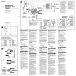
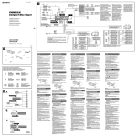
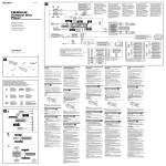
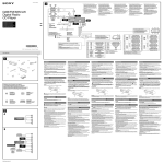
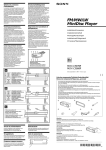
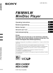
3-227-354-11 (1)
3
*1 Note for the aerial connecting
If your car aerial is an ISO (International Organisation for Standardisation) type, use the
supplied adaptor 6 to connect it.
First connect the car aerial to the supplied adaptor, then connect it to the aerial jack of
the master unit.
*2 Insert with the cord upwards
*3 RCA pin cord (not supplied)
Signalquellenwähler
(nicht mitgeliefert)
FM/MW/LW
MiniDisc Player
Selettore di fonte
(non in dotazione)
Supplied with XA-C30
Mit dem XA-C30 geliefert
Fourni avec le XA-C30
In dotazione con il modello XA-C30
Geleverd met de XA-C30
BUS AUDIO IN
from car aerial*1
von Autoantenne*1
de l’antenne de la voiture*1
dall’antenna dell’auto*1
van een auto-antenne*1
Installazione/Collegamenti
R
BUS
AUDIO
A
AMP REM
B
ATT
MDX-CA680X
MDX-CA680
*2
AUDIO OUT AUDIO OUT
REAR
FRONT
Fuse (10 A)
Sicherung (10 A)
Fusible (10 A)
Fusibile (10 A)
Zekering (10 A)
AUDIO OUT REAR
Max. supply current 0.3 A
max. Versorgungsstrom 0,3 A
Courant max. fourni 0,3 A
Alimentazione massima fornita 0,3 A
Max. voedingsstroom 0,3 A
Blue/white striped
Blau-weiß gestreift
Rayé bleu/blanc
A strisce blu e bianche
Blauw/wit gestreept
1
2
3
4
5
6
×2
8
×2
Equipment used in illustrations (not supplied)
In Abbildungen dargestellte Geräte (nicht mitgeliefert)
Appareils utilisés dans les illustrations (non fournis)
Apparecchiatura utilizzata nelle illustrazioni (non in dotazione)
Apparatuur gebruikt voor illustratiedoeleinden (niet meegeleverd)
Power amplifier
Endverstärker
Amplificateur de puissance
Amplificatore di potenza
Eindversterker
Light blue
Hellblau
Bleu ciel
Azzurro
Hemelsblauw
5
7
from the car’s power connector
vom Stromanschluß des Fahrzeugs
du connecteur d’alimentation de la voiture
dal connettore di alimentazione dell’auto
van de autovoedingsstekker
4
4
5
Yellow
Gelb
Jaune
Giallo
Geel
continuous power supply
permanente Stromversorgung
alimentation continue
alimentazione continua
continu voeding
Blue
Blau
Bleu
Blu
Blauw
power aerial control
Motorantenne
antenne électrique
comando dell’antenna elettrica
automatische antenne
7
8
5
–
Speaker, Rear, Right
Lautsprecher hinten rechts
haut-parleur, arrière, droit
Diffusore, posteriore, destro
Luidspreker, achter, rechts
6
+
Speaker, Front, Right
Lautsprecher vorne rechts
haut-parleur, avant, droit
Diffusore, anteriore, destro
Luidspreker, voor, rechts
7
–
Speaker, Front, Right
Lautsprecher vorne rechts
haut-parleur, avant, droit
Diffusore, anteriore, destro
Luidspreker, voor, rechts
+
1
2
Speaker, Rear, Right
Lautsprecher hinten rechts
haut-parleur, arrière, droit
Diffusore, posteriore, destro
Luidspreker, achter, rechts
Purple
Violett
Mauve
Viola
Paars
8
Red
Rot
Rouge
Rosso
Rood
switched power supply
geschaltete Stromversorgung
alimentation commutée
alimentazione commutata
geschakelde voeding
Black
Schwarz
Noir
Nero
Zwart
earth
Masse
masse
terra
aarding
3
4
Grey
Grau
Gris
Grigio
Grijs
Précautions
Attenzione
Let op!
• This unit is designed for negative earth 12 V DC
operation only.
• Do not get the wires under a screw, or caught in
moving parts (e.g. seat railing).
• Before making connections, turn the car ignition
off to avoid short circuits.
• Connect the power connecting cord 8 to the unit
and speakers before connecting it to the auxiliary
power connector.
• Run all earth wires to a common earth point.
• Be sure to insulate any loose unconnected wires
with electrical tape for safety.
• Dieses Gerät ist ausschließlich für den Betrieb bei
12 V Gleichstrom (negative Erdung) bestimmt.
• Achten Sie darauf, daß die Kabel nicht unter einer
Schraube oder zwischen beweglichen Teilen wie
z. B. in einer Sitzschiene eingeklemmt werden.
• Schalten Sie, bevor Sie irgendwelche Anschlüsse
vornehmen, die Zündung des Fahrzeugs aus, um
Kurzschlüsse zu vermeiden.
• Verbinden Sie das Stromversorgungskabel 8 mit
dem Gerät und den Lautsprechern, bevor Sie es
mit dem Hilfsstromanschluß verbinden.
• Schließen Sie alle Erdungskabel an einen
gemeinsamen Massepunkt an.
• Aus Sicherheitsgründen müssen alle losen, nicht
angeschlossenen Drähte mit Isolierband abisoliert
werden.
• Cet appareil est conçu pour fonctionner sur
courant continu de 12 V avec masse négative.
• Evitez de fixer des vis sur les câbles ou de coincer
ceux-ci dans des pièces mobiles (par exemple,
armature de siège).
• Avant d’effectuer des raccordements, éteignez le
moteur pour éviter les courts-circuits.
• Branchez le cordon d’alimention 8 sur l’appareil
et les haut-parleurs avant de le brancher sur le
connecteur d’alimentation auxiliaire.
• Rassemblez tous les fils de terre en un point de
masse commun.
• Veillez à isoler avec du chatterton tout fil lâche
non raccordé.
• Questo apparecchio è stato progettato per l’uso
solo a 12 V CC con massa negativa.
• Evitare che i cavi rimangano bloccati da una vite o
incastrati nelle parti mobili (ad esempio nelle
guide scorrevoli dei sedili).
• Prima di effettuare i collegamenti, spegnere il
motore dell’automobile onde evitare di causare
cortocircuiti.
• Collegare il cavo di collegamento
dell’alimentazione 8 all’apparecchio e ai
diffusori prima di collegarlo al connettore di
alimentazione ausiliare.
• Portare tutti i cavi di massa a un punto di
massa comune.
• Per sicurezza, assicurarsi di isolare qualsiasi cavo
non collegato mediante apposito nastro.
• Dit apparaat is ontworpen voor gebruik op
gelijkstroom van een 12 Volts auto-accu, negatief
geaard.
• Zorg ervoor dat de draden niet onder een schroef
of tussen bewegende onderdelen (b.v. zetelrail)
terechtkomen.
• Alvorens aansluitingen te verrichten moet u het
contact afzetten om kortsluiting te vermijden.
• Sluit het netsnoer 8 aan op het toestel en de
luidsprekers vooraleer u het op de
hulpvoedingsaansluiting aansluit.
• Sluit alle aarddraden op een
gemeenschappelijk aardpunt aan.
• Voorzie niet aangesloten draden om
veiligheidsredenen altijd van isolatietape.
Parts list (1)
The numbers in the list are keyed to those in the
instructions.
Handle the bracket 1 carefully to avoid injuring
your fingers.
Teileliste (1)
Die Nummern in der Liste sind dieselben wie im
Erläuterungstext.
Vorsicht
Remarques sur le cordon d’alimentation (jaune)
• Lorsque cet appareil est raccordé à d’autres
éléments stéréo, la valeur nominale des circuits de
la voiture raccordée doit être supérieure à la
somme des fusibles de chaque élément.
• Si aucun circuit de la voiture n’est assez puissant,
raccordez directement l’appareil à la batterie.
Liste des composants (1)
Note sul cavo di alimentazione (giallo)
• Se questo apparecchio viene collegato con altri
componenti stereo, la potenza nominale dei
circuiti dell’automobile deve essere superiore a
quella prodotta dalla somma dei fusibili di
ciascun componente.
• Se la potenza nominale dei circuiti
dell’automobile non è sufficiente, collegare
l’apparecchio direttamente alla batteria.
Les numéros de l’illustration correspondent à ceux
des instructions.
Attention
Elenco dei componenti (1)
Manipulez précautionneusement le support 1
pour éviter de vous blesser aux doigts.
I numeri nella lista corrispondono a quelli riportati
nelle istruzioni.
Seien Sie beim Umgang mit der Halterung 1
vorsichtig, damit Sie sich nicht die Hände verletzen.
Rotary commander RM-X4S
Joystick RM-X4S
Satellite de commande RM-X4S
Telecomando a rotazione RM-X4S
Bedieningssatelliet RM-X4S
8
Opmerkingen bij de voedingskabel (geel)
• Wanneer u dit toestel aansluit samen met andere
componenten, moet het vermogen van de
aangesloten autostroomkring groter zijn dan de som
van de zekeringen van elke component afzonderlijk.
• Wanneer het vermogen ontoereikend is, moet u
het toestel rechtstreeks aansluiten op de batterij.
Onderdelenlijst (1)
De nummers in de afbeelding verwijzen naar die in
de montage-aanwijzingen.
Voorzichtig
Houd de beugel 1 voorzichtig vast zodat u uw
vingers niet verwondt.
Attenzione
Maneggiare la staffa 1 con cautela per evitare di
ferirsi le mani.
Connection example (2)
Notes (2-A)
• Be sure to connect the earth cord before
connecting the amplifier.
• If you connect an optional power amplifier and do
not use the built-in amplifier, the beep sound will
be deactivated.
2 A
Tip (2-B- )
For connecting two or more CD/MD changers, the
source selector XA-C30 (optional) is necessary.
AUDIO OUT FRONT
Connection diagram (3)
A To AMP REMOTE IN of an optional power
Exemple de raccordement (2)
Anschlußbeispiel (2)
Hinweise (2-A)
• Schließen Sie unbedingt zuerst das Massekabel an,
bevor Sie den Verstärker anschließen.
• Wenn Sie einen gesondert erhältlichen
Endverstärker anschließen und den integrierten
Verstärker nicht benutzen, wird der Signalton
deaktiviert.
Tip (2-B- )
Zum Anschließen von zwei oder mehr CD/MDWechslern wird der gesondert erhältliche
Signalquellenwähler XA-C30 benötigt.
amplifier
This connection is only for amplifiers. Connecting
any other system may damage the unit.
B To the interface cable of a car telephone
Anschlußdiagramm (3)
A An AMP REMOTE IN des gesondert erhältlichen
Warning
AUDIO OUT REAR
B
If you have a power aerial without a relay box,
connecting this unit with the supplied power
connecting cord 8 may damage the aerial.
BUS AUDIO IN
Notes on the control leads
• The power aerial control lead (blue) supplies +12 V
DC when you turn on the tuner or when you
activate the AF (Alternative Frequency), TA (Traffic
Announcement) function.
• When your car has built-in FM/MW/LW aerial in
the rear/side glass, connect the power aerial
control lead (blue) or the accessory power input
lead (red) to the power terminal of the existing
aerial booster. For details, consult your dealer.
• A power aerial without a relay box cannot be used
with this unit.
Memory hold connection
When the yellow power input lead is connected,
power will always be supplied to the memory circuit
even when the ignition switch is turned off.
BUS CONTROL IN
BUS AUDIO IN
Source selector*
Signalquellenwähler*
Sélecteur de source*
Selettore di fonte*
Geluidsbronkiezer*
* not supplied
nicht mitgeliefert
non fourni
non in dotazione
niet bijgeleverd
BUS CONTROL IN
Notes on speaker connection
• Before connecting the speakers, turn the unit off.
• Use speakers with an impedance of 4 to 8 ohms,
and with adequate power handling capacities to
avoid its damage.
• Do not connect the speaker terminals to the car
chassis, or connect the terminals of the right
speakers with those of the left speaker.
• Do not connect the earth lead of this unit to the
negative (–) terminal of the car.
• Do not attempt to connect the speakers in parallel.
• Connect only passive speakers. Connecting active
speakers (with built-in amplifiers) to the speaker
terminals may damage the unit.
• To avoid malfunction, do not use the built-in
speaker wires installed in your car if its unit end
share a common negative (–) lead for the right and
left speakers.
• Do not connect the unit’s speaker cords to each
other.
Endverstärkers
Dieser Anschluß ist ausschließlich für Verstärker
gedacht. Schließen Sie nichts anderes daran an.
Andernfalls kann das Gerät beschädigt werden.
B An Schnittstellenkabel eines Autotelefons
Warnung
Remarques (2-A)
• Raccordez d’abord le fil de masse avant de
raccorder l’amplificateur.
• Si vous raccordez un amplificateur de puissance
indépendant et que vous n’utilisez pas
l’amplificateur intégré, le bip sonore est désactivé.
Conseil (2-B- )
Dans le cas du raccordement de deux changeurs de
CD/MD ou plus, le sélecteur de source XA-C30 (en
option) est indispensable.
Schéma de raccordement (3)
A Au niveau du AMP REMOTE IN d’un
amplificateur de puissance facultatif
Ce raccordement existe seulement pour les
amplificateurs. Le raccordement à tout autre
système peut endommager l’appareil.
B Vers le cordon de liaison d’un téléphone de
voiture
Avertissement
Wenn Sie eine Motorantenne ohne Relaiskästchen
verwenden, kann durch Anschließen dieses Geräts
mit dem mitgelieferten Stromversorgungskabel 8
die Antenne beschädigt werden.
Si vous disposez d’une antenne électrique sans
boîtier de relais, le branchement de cet appareil au
moyen du cordon d’alimentation fourni 8 risque
d’endommager l’antenne.
Hinweise zu den Steuerleitungen
• Die Motorantennen-Steuerleitung (blau) liefert
+ 12 V Gleichstrom, wenn Sie den Tuner
einschalten oder die AF- (Alternativfrequenzsuche)
oder die TA-Funktion (Verkehrsdurchsagen)
aktivieren.
• Wenn das Fahrzeug mit einer in der Heck-/
Seitenfensterscheibe integrierten FM (UKW)/MW/
LW-Antenne ausgestattet ist, schließen Sie die
Motorantennen-Steuerleitung (blau) oder die
Zubehörstromversorgungsleitung (rot) an den
Stromversorgungsanschluß des vorhandenen
Antennenverstärkers an. Näheres dazu erfahren
Sie bei Ihrem Händler.
• Es kann nur eine Motorantenne mit Relaiskästchen
angeschlossen werden.
Remarques sur les fils de contrôle
• Le fil de commande (bleu) de l’antenne électrique
assure une alimentation de
+12 V CC lorsque vous mettez le syntoniseur sous
tension ou lorsque vous activez la fonction AF
(fréquence secondaire) ou TA (informations
routières).
• Lorsque votre voiture est équipée d’une antenne
FM/MW/LW intégrée dans la vitre arrière/latérale,
raccordez la sortie de commande de l’antenne
(bleu) ou l’entrée d’alimentation des accessoires
(rouge) au bornier de l’amplificateur d’antenne
existant. Pour plus de détails, consultez votre
revendeur.
• Une antenne électrique sans boitier de relais ne
peut pas être utilisée avec cet appareil.
Stromversorgung des Speichers
Wenn das gelbe Stromversorgungskabel
angeschlossen ist, wird der Speicher stets (auch bei
ausgeschalteter Zündung) mit Strom versorgt.
Hinweise zum Lautsprecheranschluß
• Schalten Sie das Gerät aus, bevor Sie die
Lautsprecher anschließen.
• Verwenden Sie Lautsprecher mit einer Impedanz
zwischen 4 und 8 Ohm und ausreichender
Belastbarkeit. Ansonsten können die Lautsprecher
beschädigt werden.
• Verbinden Sie die Lautsprecheranschlüsse nicht mit
dem Wagenchassis, und verbinden Sie auch nicht
die Anschlüsse des rechten mit denen des linken
Lautsprechers.
• Verbinden Sie die Masseleitung dieses Geräts nicht
mit dem negativen (–) Lautsprecheranschluß.
• Versuchen Sie nicht, Lautsprecher parallel
anzuschließen.
• An die Lautsprecheranschlüsse dieses Geräts
dürfen nur Passivlautsprecher angeschlossen
werden. Schließen Sie keine Aktivlautsprecher
(Lautsprecher mit eingebauten Verstärkern) an, da
diese sonst beschädigt werden können.
• Um Fehlfunktionen zu vermeiden, verwenden Sie
nicht die im Fahrzeug installierten, integrierten
Lautsprecherleitungen, wenn am Ende eine
gemeinsame negative (–) Leitung für den rechten
und den linken Lautsprecher verwendet wird.
• Verbinden Sie nicht die Lautsprecherkabel des
Geräts miteinander.
5
7
2
4
6
8
Raccordement pour la conservation de la mémoire
Lorsque le fil d’entrée d’alimentation jaune est
raccordé, le circuit de la mémoire est alimenté en
permanence même si la clé de contact est sur la
position d’arrêt.
Remarques sur le raccordement des haut-parleurs
• Avant de raccorder les haut-parleurs, mettez
l’appareil hors tension.
• Utilisez des haut-parleurs ayant une impédance de
4 à 8 ohms avec une capacité de manipulation
adéquate pour éviter de les endommager.
• Ne raccordez pas les bornes du système de hautparleurs au châssis de la voiture et ne raccordez
pas les bornes du haut-parleur droit à celles du
haut-parleur gauche.
• Ne raccordez pas le câble de masse de cet appareil
à la borne négative (–) de l’enceinte.
• N’essayez pas de raccorder les haut-parleurs en
parallèle.
• Raccordez uniquement des haut-parleurs passifs.
Le raccordement de haut-parleurs actifs (avec
amplificateurs intégrés) aux bornes des hautparleurs peut endommager l’appareil.
• Pour éviter tout dysfonctionnement, n’utilisez pas
les fils des haut-parleurs intégrés installés dans
votre voiture si l’appareil partage un fil négatif
commun (–) pour les haut-parleurs droit et gauche.
• Ne raccordez pas entre eux les cordons des hautparleurs de l’appareil.
Voorbeeldaansluitingen (2)
Esempi di collegamento (2)
Note (2-A)
• Assicurarsi di collegare il cavo di terra prima di
collegare l’apparecchio all’amplificatore.
• Se si collega un amplificatore di potenza opzionale
e non si utilizza l’amplificatore incorporato, il
segnale acustico verrà disattivato.
Suggerimento (2-B- )
Per collegare due o più cambia CD/MD, si deve
utilizzare il selettore di fonte XA-C30 (opzionale).
Opmerkingen (2-A)
• Sluit eerst de massakabel aan alvorens de
versterker aan te sluiten.
• Als u een los verkrijgbare vermogensversterker
aansluit en de ingebouwde versterker niet
gebruikt, is de pieptoon uitgeschakeld.
Tip (2-B- )
Om twee of meer CD/MD-wisselaars aan te sluiten,
hebt u de geluidsbronkiezer XA-C30 (optioneel)
nodig.
Aansluitschema (3)
Schema di collegamento (3)
A A AMP REMOTE IN di un amplificatore di
potenza opzionale
Questo collegamento è riservato esclusivamente
agli amplificatori. Non collegare un tipo di
sistema diverso onde evitare di causare danni
all’apparecchio.
B Al cavo interfaccia di un telefono per auto
Avvertenza
Quando si collega l’apparecchio con il cavo di
alimentazione in dotazione 8, si potrebbe
danneggiare l’antenna elettrica se questa non ha la
scatola di relè.
Note sui cavi di controllo
• Il cavo di controllo dell’antenna elettrica (blu)
fornisce corrente continua +12 V CC quando si
accende il sintonizzatore o quando si attiva la
funzione AF (frequenza alternativa) o TA
(notiziario sul traffico).
• Se l’automobile è dotata di antenna FM/MW/LW
incorporata nel vetro posteriore/laterale, collegare il
cavo (blu) di controllo dell’antenna elettrica o il cavo
(rosso) di ingresso dell’alimentazione opzionale al
terminale di alimentazione del preamplificatore
dell’antenna esistente. Per ulteriori informazioni,
consultare il proprio fornitore.
• Non è possibile usare un’antenna elettrica senza
scatola a relè con questo apparecchio.
Collegamento per la conservazione della memoria
Quando il cavo di ingresso alimentazione giallo è
collegato, viene sempre fornita alimentazione al
circuito di memoria anche quando la chiavetta a
accensione è spenta.
Note sul collegamento dei diffusori
• Prima di collegare i diffusori spegnere
l’apparecchio.
• Usare diffusori di impedenza compresa tra 4 e 8
ohm e con capacità di potenza adeguata,
altrimenti i diffusori potrebbero venir danneggiati.
• Non collegare i terminali del sistema diffusori al
telaio dell’auto e non collegare i terminali del
diffusore destro a quelli del diffusore sinistro.
• Non collegare il cavo di terra di questo
apparecchio al terminale negativo (–) del diffusore.
• Non collegare i diffusori in parallelo.
• Non collegare alcun diffusore attivo (con
amplificatore incorporato) ai terminali dei diffusori
dell’apparecchio perché si potrebbero danneggiare
i diffusori attivi. Assicurarsi di collegare diffusori
passivi a questi terminali.
• Per evitare problemi di funzionamento, non
utilizzare i cavi dei diffusori incorporati installati
nell’automobile se il terminale dell’apparecchio
condivide un cavo comune negativo (–) per i
diffusori destro e sinistro.
• Non collegare fra loro i cavi dei diffusori
dell’apparecchio.
+
Speaker, Front, Left
Lautsprecher vorne links
haut-parleur, avant, gauche
Diffusore, anteriore, sinistro
Luidspreker, voor, links
–
Speaker, Front, Left
Lautsprecher vorne links
haut-parleur, avant, gauche
Diffusore, anteriore, sinistro
Luidspreker, voor, links
+
Speaker, Rear, Left
Lautsprecher hinten links
haut-parleur, arrière, gauche
Diffusore, posteriore, sinistro
Luidspreker, achter, links
–
Speaker, Rear, Left
Lautsprecher hinten links
haut-parleur, arrière, gauche
Diffusore, posteriore, sinistro
Luidspreker, achter, links
White
Weiß
Blanc
Bianco
Wit
Green
Grün
Vert
Verde
Groen
Negative polarity positions 2, 4, 6, and 8 have striped cords.
An den negativ gepolten Positionen (2, 4, 6 und 8) befinden sich gestreifte Adern.
Les positions de polarité négative 2, 4, 6 et 8 sont dotées de cordons rayés.
Le posizioni a polarità negativa 2, 4, 6 e 8 hanno cavi rigati.
De negatieve posities 2, 4, 6 en 8 hebben gestreepte kabels.
Vorsicht
Hinweise zum Stromversorgungskabel (gelb)
• Wenn Sie dieses Gerät zusammen mit anderen
Stereokomponenten anschließen, muß der
Autostromkreis, an den die Geräte angeschlossen
sind, eine höhere Leistung aufweisen als die
Summe der Sicherungen der einzelnen
Komponenten.
• Wenn kein Autostromkreis eine so hohe Leistung
aufweist, schließen Sie das Gerät direkt an die
Batterie an.
3
from the car’s speaker connector
vom Lautsprecheranschluß des Fahrzeugs
du connecteur de haut-parleur de la voiture
dal connettore del diffusore dell’auto
van de autoluidsprekerstekker
Cautions
Notes on the power supply cord (yellow)
• When connecting this unit in combination with
other stereo components, the connected car
circuit’s rating must be higher than the sum of
each component’s fuse.
• When no car circuits are rated high enough,
connect the unit directly to the battery.
1
8
Positions 1, 2, 3 and 6 do not have pins.
An Position 1, 2, 3 und 6 befinden sich keine Stifte.
Les positions 1, 2, 3 et 6 ne comportent pas de broches.
Le posizioni 1, 2, 3 e 6 non hanno piedini.
De posities 1, 2, 3 en 6 hebben geen pins.
Caution
CD/MD changer
CD/MD-Wechsler
Changeur de CD/MD
Cambia CD/MD
CD/MD-wisselaar
*1 Opmerking bij de antenne-aansluiting
Indien uw wagen is uitgerust met een antenne van het type ISO (International
Organisation for Standardization), moet u die aansluiten met behulp van de
meegeleverde adaptor 6.
Sluit eerst de auto-antenne aan op de meegeleverde adaptor en vervolgens de
antennestekker op het hoofdtoestel.
*2 Inbrengen met het snoer naar boven
*3 Tulpstekkersnoer (niet bijgeleverd)
BUS CONTROL IN
See “Power Connection diagram” on the reverse side for
details.
Näheres dazu finden Sie im “Stromanschlußdiagramm”.
Blättern Sie dazu bitte um.
Voir le “Schéma de connexion d’alimentation” au verso
pour plus de détails.
Per ulteriori informazioni, vedere “Diagramma dei
collegamenti di alimentazione” che si trova sul retro.
Zie “Voedingsaansluitschema” op de achterkant voor
meer details.
Sony Corporation © 2001 Printed in Thailand
Rear speaker
Hecklautsprecher
Haut-parleur arrière
Diffusori posteriori
Achterluidspreker
*1 Nota per il collegamento dell’antenna
Se la vostra antenna della macchina è di tipo ISO (International Organization
Standardization), utilizzare l’adattatore 6 in dotazione per collegarla.
Collegare prima l’antenna della macchina all’adattatore in dotazione, quindi collegarla
alla presa dell’antenna dell’apparecchio principale.
2
* Inserire con il cavo rivolto verso l’alto
3
* Cavo a piedini RCA (non in dotazione)
L
6
Montage/Aansluitingen
Front speaker
Frontlautsprecher
Haut-parleur avant
Diffusori anteriori
Voorluidspreker
XA-C30
REMOTE IN
Installation/Connexions
7
*1 Remarque sur le raccordement de l’antenne
Si votre antenne de voiture est de type ISO (organisation internationale de
normalisation), utilisez l’adaptateur fourni 6 pour la raccorder.
Raccordez d’abord l’antenne de voiture à l’adaptateur fourni et, ensuite, à la prise
d’antenne de l’appareil principal.
*2 Insérez avec le câble vers le haut
*3 Cordon à broche RCA (non fourni)
Geluidsbronkiezer
(niet bijgeleverd)
AUDIO OUT
FRONT
Installation/Anschluß
1
Supplied with the CD/MD changer
Mit dem CD/MD-Wechsler geliefert
Fourni avec le changeur de CD/MD
In dotazione con il cambia CD/MD
Geleverd met de CD/MD-wisselaar
Sélecteur de source
(non fourni)
*3
Installation/Connections
*1 Hinweis zum Anschließen der Antenne
Wenn Ihre Fahrzeugantenne der ISO-Norm (ISO = International Organization for
Standardization - Internationale Normungsgemeinschaft) entspricht, schließen Sie sie mit
Hilfe des mitgelieferten Adapters 6 an.
Verbinden Sie zuerst die Fahrzeugantenne mit dem mitgelieferten Adapter, und
verbinden Sie diesen dann mit der Antennenbuchse des Hauptgeräts.
2
* Mit dem Kabel nach oben einsetzen!
3
* Cinchkabel (nicht mitgeliefert)
Source selector (not
supplied)
*3
A Naar AMP REMOTE IN van een los verkrijgbare
vermogensversterker
Deze aansluiting is alleen bedoeld voor
versterkers. Door een ander systeem aan te sluiten
kan het toestel worden beschadigd.
B Naar het interface-snoer van een autotelefoon
Opgelet
Indien u een elektrische antenne heeft zonder
relaiskast, kan het aansluiten van deze eenheid met
het bijgeleverde netsnoer 8 de antenne
beschadigen.
Opmerking betreffende de aansluitsnoeren
• De voedingskabel (blauw) van de elektrisch
bediende antenne levert +12V gelijkstroom
wanneer u de tuner aanschakelt of de functie AF
(Alternative Frequency) of TA (Traffic
Announcement) activeert.
• Wanneer uw auto is uitgerust met een FM/MW/
LW-antenne in de achterruit/voorruit, moet u de
antennevoedingskabel (blauw) of de
hulpvoedingskabel (rood) aansluiten op de
voedingsingang van de bestaande
antenneversterker. Raadpleeg uw dealer voor
meer details.
• Met dit apparaat is het niet mogelijk een
automatische antenne zonder relaishuis te
gebruiken.
Instandhouden van het geheugen
Zolang de gele stroomdraad is aangesloten, blijft de
stroomvoorziening van het geheugen intact, ook
wanneer het contact van de auto wordt
uitgeschakeld.
Opmerkingen betreffende het aansluiten van de
luidsprekers
• Zorg dat het apparaat is uitgeschakeld, alvorens de
luidsprekers aan te sluiten.
• Gebruik luidsprekers met een impedantie van 4 tot
8 Ohm en let op dat die het vermogen van de
versterker kunnen verwerken. Als dit wordt
verzuimd, kunnen de luidsprekers ernstig
beschadigd raken.
• Verbind in geen geval de aansluitingen van de
luidsprekers met het chassis van de auto en sluit de
aansluitingen van de rechter en linker luidspreker
niet op elkaar aan.
• Verbind de massakabel van dit toestel niet met de
negatieve (–) aansluiting van de luidspreker.
• Probeer nooit de luidsprekers parallel aan te
sluiten.
• Sluit geen actieve luidsprekers (met ingebouwde
versterkers) aan op de luidspreker-aansluiting van
dit apparaat. Dit zal leiden tot beschadiging van
de actieve luidsprekers. Sluit dus altijd uitsluitend
luidsprekers zonder ingebouwde versterker aan.
• Om defecten te vermijden mag u de bestaande
luidsprekerbedrading in uw auto niet gebruiken
wanneer er een gemeenschappelijke negatieve (–)
draad is voor de rechter en linker luidsprekers.
• Verbind de luidsprekerdraden niet met elkaar.
4 A
Power connection diagram
B
A
c
B
1
Auxiliary power connector may vary depending on
the car. Check your car’s auxiliary power connector
diagram to make sure the connections match
correctly. There are three basic types (illustrated
below). You may need to switch the positions of the
red and yellow leads in the car stereo’s power
connecting cord.
After matching the connections and switched
power supply leads correctly, connect the unit to
the car’s power supply. If you have any questions
and problems connecting your unit that are not
covered in this manual, please consult the car
dealer.
2
5 1
2
3
4
Dashboard
Armaturenbrett
Tableau de bord
Cruscotto
Dashboard
Fire wall
Motorraumtrennwand
Paroi ignifuge
Parete tagliafiamma
Brandschot
1
5
5
Bend these claws outward for a tight fit,
if necessary.
7
7
Indien nodig kunt u deze lipjes
ombuigen voor een steviger bevestiging.
3
7
5
Precautions
Vorsichtsmaßnahmen
Précautions
Precauzioni
Voorzorgsmaatregelen
• Choose the installation location carefully so that
the unit will not interfere with normal driving
operations.
• Avoid installing the unit in areas subject to dust,
dirt, excessive vibration, or high temperature,
such as in direct sunlight or near heater ducts.
• Use only the supplied mounting hardware for a
safe and secure installation.
• Wählen Sie den Einbauort sorgfältig so aus, daß
das Gerät beim Fahren nicht hinderlich ist.
• Bauen Sie das Gerät so ein, daß es keinen hohen
Temperaturen (keinem direkten Sonnenlicht,
keiner Warmluft von der Heizung), keinem Staub,
keinem Schmutz und keinen starken Vibrationen
ausgesetzt ist.
• Für eine sichere Befestigung verwenden Sie stets
nur die mitgelieferten Montageteile.
• Choisissez soigneusement l’emplacement de
l’installation afin que l’appareil ne gêne pas la
conduite normale du véhicule.
• Evitez d’installer l’appareil dans un endroit
exposé à la poussière, à la saleté, à des vibrations
excessives ou à des températures élevées comme
en plein soleil ou à proximité de conduits de
chauffage.
• Pour garantir un montage sûr, n’utilisez que le
matériel fourni.
• Scegliere con attenzione la posizione per
l’installazione in modo che l’apparecchio non
interferisca con le operazioni di guida del
conducente.
• Evitare di installare l’apparecchio dove sia
soggetto ad alte temperature, come alla luce
solare diretta o al getto di aria calda dell’impianto
di riscaldamento, o dove possa essere soggetto a
polvere, sporco e vibrazioni eccessive.
• Usare solo il materiale di montaggio in dotazione
per un’installazione stabile e sicura.
• Kies de installatieplaats zorgvuldig zodat het
toestel de bestuurder niet hindert tijdens het
rijden.
• Installeer het apparaat niet op plaatsen waar het
blootgesteld wordt aan hoge temperaturen, b.v. in
direct zonlicht of bij de warme luchtstroom van
de autoverwarming, aan sterke trillingen, of waar
het in contact komt met veel stof of vuil.
• Gebruik voor het veilig en stevig monteren van
het apparaat uitsluitend de bijgeleverde montageonderdelen.
Regolazione dell’angolo di montaggio
Maximale montagehoek
Regolare l’angolo di montaggio in modo che sia
inferiore a 20°.
Installeer het apparaat nooit onder een hoek van
meer dan 20° met het horizontale vlak.
Come rimuovere e reinserire il
pannello anteriore (4)
Verwijderen en bevestigen van
het afneembare voorpaneel
(4)
Hinweis zum Montagewinkel
Das Gerät sollte in einem Winkel von weniger als
20° montiert werden.
How to detach and attach the
front panel (4)
Ajustez l’inclinaison à un angle inférieur à 20°.
Abnehmen und Anbringen der
Frontplatte (4)
Retrait et pose de la façade
(4)
Nehmen Sie die Frontplatte vor dem Einbau des
Geräts ab.
Avant d’installer l’appareil, retirez la façade.
4-A To detach
4-B To attach
Place the hole A in the front panel onto the spindle
B on the unit as illustrated, then push the left side
in.
Mounting example (5)
4-A Pour retirer
4-A Abnehmen
Drücken Sie auf jeden Fall (OFF), bevor Sie die
Frontplatte abnehmen. Drücken Sie (OPEN),
schieben Sie dann die Frontplatte nach rechts, und
ziehen Sie sie an der linken Seite heraus.
Setzen Sie die Aussparung A an der Frontplatte
wie in der Abbildung dargestellt am Stift B am
Gerät an, und drücken Sie dann die linke Seite
hinein.
Installation in the dashboard
Be sure to press (OFF) on the unit for two
seconds to turn off the clock display after
turning off the engine.
When you press (OFF) only momentarily, the clock
display does not turn off and this causes battery
wear.
RESET button
Fixez la partie A de la façade sur la partie B de
l’appareil, comme indiqué sur l’illustration, puis
appuyez sur le côté gauche jusqu’au déclic.
Exemple de montage (5)
Montagebeispiel (5)
Warning when installing in a car
without ACC (accessory)
position on the ignition key
switch
Avant de retirer la façade, n’oubliez pas d’appuyer
d’abord sur (OFF). Appuyez sur (OPEN), puis
faites glisser la façade vers la droite et retirez-la par
la gauche.
4-B Pour poser
4-B Anbringen
Drücken Sie am Gerät unbedingt zwei Sekunden
lang (OFF), um die Uhrzeitanzeige
auszuschalten, nachdem Sie den Motor
ausgeschaltet haben.
Wenn Sie (OFF) nur kurz drücken, wird die
Uhrzeitanzeige nicht ausgeschaltet, und der
Autobatterie wird Strom entzogen.
When the installation and connections are
completed, be sure to press the RESET button with
a ballpoint pen, etc.
Taste RESET
Nach der Installation und dem Anschluß muß die
Taste RESET mit einem Kugelschreiber o. ä.
gedrückt werden.
Le connecteur d’alimentation auxiliaire peut varier
suivant le type de voiture. Vérifiez le schéma du
connecteur d’alimentation auxiliaire de votre
voiture pour vous assurer que les connexions
correspondent. Il en existe trois types de base
(illustrés ci-dessous). Il se peut que vous deviez
commuter la position du fil rouge et jaune du
cordon d’alimentation de l’autoradio.
Après avoir établi les connexions et commuté
correctement les fils d’alimentation, raccordez
l’appareil à l’alimentation de la voiture. Si vous
avez des questions ou des difficultés à propos de
cet appareil qui ne sont pas abordées dans le
présent mode d’emploi, consultez votre revendeur
automobile.
Auxiliary power connector
Hilfsstromanschluß
Connecteur d’alimentation auxiliaire
Connettore di alimentazione ausiliare
Hulpvoedingsaansluiting
Prima di installare l’apparecchio rimuovere il
pannello anteriore.
4-A Per rimuoverlo
Prima di rimuovere il pannello anteriore,
assicurarsi di premere (OFF). Premere (OPEN),
quindi far scivolare il pannello anteriore verso
destra e tirare il lato sinistro verso di sé.
4-B Per reinserirlo
Applicare la foro A del pannello anteriore al
mandrino B dell’apparecchio come mostrato
nell’illustrazione e premere il lato sinistro fino a
sentire uno scatto.
Esempio di montaggio (5)
Avertissement en cas
d’installation dans une voiture
dont le contact ne comporte
pas de position ACC
(accessoires)
Appuyez sur la touche (OFF) de l’appareil
pendant deux secondes pour désactiver
l’affichage de l’horloge après avoir coupé le
moteur.
Si vous n’appuyez que brièvement sur (OFF),
l’affichage de l’horloge ne disparaît pas, ce qui
provoque la décharge de la batterie.
Installazione nel cruscotto
Informazioni importanti per
quando si effettua
l’installazione su un’auto
sprovvista della posizione ACC
sull’interruttore di accensione
Assicurarsi di premere (OFF) sull’apparecchio
per due secondi per spegnere il display
dell’orologio dopo che il motore è stato spento.
Se si preme (OFF) solo per un attimo, il display
dell’orologio non si spegne causando in questo
modo lo scaricamento della batteria.
Touche RESET
Quand l’installation et les raccordements sont
terminés, appuyez sur la touche RESET avec un
stylo à bille, etc.
Dopo avere terminato l’installazione e i
collegamenti, assicurarsi di premere il tasto RESET
con la punta di una penna a sfera, ecc.
Red
Rot
Rouge
Rosso
Rood
Yellow
Gelb
Jaune
Giallo
Geel
Yellow
Gelb
Jaune
Giallo
Geel
4-A Verwijderen
Druk eerst op (OFF) alvorens het voorpaneel los te
maken. Druk op (OPEN), schuif het voorpaneel
naar rechts en trek het los aan de linkerkant.
4-B Bevestigen
Breng deel A van het voorpaneel aan op deel B
van het apparaat zoals afgebeeld en druk op de
linkerzijde tot deze vastklikt.
Montagevoorbeeld (5)
4
Yellow
Gelb
Jaune
Giallo
Geel
continuous power supply
permanente Stromversorgung
alimentation continue
alimentazione continua
continu voeding
7
Red
Rot
Rouge
Rosso
Rood
switched power supply
geschaltete Stromversorgung
alimentation commutée
alimentazione commutata
geschakelde voeding
Montage in het dashboard
Opgelet bij het monteren in een
auto waarvan het contactslot
geen ACC (accessory) stand
heeft
Red
Rot
Rouge
Rosso
Rood
Red
Rot
Rouge
Rosso
Rood
Yellow
Gelb
Jaune
Giallo
Geel
Yellow
Gelb
Jaune
Giallo
Geel
Druk (OFF) op het toestel gedurende twee
seconden in om de klokweergave uit te
schakelen na het afzetten van de motor.
Indien u slechts even op (OFF) drukt, verdwijnt de
tijdindicatie niet waardoor de batterij uitgeput
raakt.
RESET-toets
Tasto RESET
Red
Rot
Rouge
Rosso
Rood
Verwijder, alvorens met het installeren te
beginnen, het afneembare voorpaneel.
Installation dans le tableau de bord
Installation im Armaturenbrett
Warnhinweis zur Installation
des Geräts in einem Auto mit
Zündschloß ohne
Zubehörposition ACC oder I
De hulpvoedingsaansluiting kan verschillen
naargelang van de wagen. Controleer het
voedingsaansluitschema dat bij dit toestel wordt
geleverd om te zien of de aansluitingen kloppen. Er
zijn drie basistypes (zie illustratie hieronder).
Als de aansluitingen en geschakelde
voedingskabels kloppen, sluit u het toestel aan op
de voeding van de wagen. Indien u nog vragen of
problemen hebt in verband met het aansluiten van
het toestel die niet in deze handleiding vermeld
staan, raadpleeg dan de autodealer.
Réglage de l’angle de montage
Before installing the unit, detach the front
panel.
Before detaching the front panel, be sure to press
(OFF). Press (OPEN), then slide the front panel to
the right side, and pull out the left side.
Voedingsaansluitschema
Der Hilfsstromanschluß kann je nach Fahrzeugtyp
unterschiedlich sein. Sehen Sie im
Hilfsstromanschlußdiagramm für Ihr Fahrzeug
nach, wie die Verbindung ordnungsgemäß
vorgenommen werden muß. Es gibt, wie unten
abgebildet, drei grundlegende Typen.
Sie müssen möglicherweise die rote und gelbe
Leitung des Stromversorgungskabels der
Autostereoanlage vertauschen.
Stellen Sie die Anschlüsse her, schließen Sie die
geschalteten Stromversorgungsleitungen richtig an,
und verbinden Sie dann das Gerät mit der
Stromversorgung Ihres Fahrzeugs. Wenn beim
Anschließen des Geräts Fragen oder Probleme
auftreten, die in dieser Bedienungsanleitung nicht
erläutert werden, wenden Sie sich bitte an den
Autohändler.
Schéma de connexion
d’alimentation
Piegare questi morsetti per
un‘installazione più sicura, se necessario.
Adjust the mounting angle to less than 20°.
Stromanschlußdiagramm
2
Pliez ces griffes pour assurer une prise
correcte si nécessaire.
Mounting angle adjustment
Il connettore di alimentazione ausiliaria può variare
a seconda della macchina.
Controllare il diagramma del connettore di
alimentazione ausiliaria della macchina per essere
sicuri che le connessioni corrispondano
correttamente. Vi sono tre tipi di base (illustrazione
sotto). Potrà essere necessario cambiare le posizioni
dei conduttori rosso e giallo nel cavo di
alimentazione dello stereo della macchina. Dopo
aver fatto corrispondere le connessioni e i cavi di
alimentazione commutata, collegare l’apparecchio
all’alimentazione della macchina. Se si hanno
domande o se sorgono problemi che non sono stati
trattati nel manuale nel collegare l’apparecchio,
contattare l’autoconcessionario.
4
Falls erforderlich, diese Klammern für
einen sicheren Halt hochbiegen.
1
Diagramma dei collegamenti di
alimentazione
Druk, nadat u het apparaat heeft geïnstalleerd en de
aansluitingen heeft gemaakt, met een balpen of een
ander puntig voorwerp op de RESET-toets.
4
Yellow
Gelb
Jaune
Giallo
Geel
switched power supply
geschaltete Stromversorgung
alimentation commutée
alimentazione commutata
geschakelde voeding
7
Red
Rot
Rouge
Rosso
Rood
continuous power supply
permanente Stromversorgung
alimentation continue
alimentazione continua
continu voeding
Red
Rot
Rouge
Rosso
Rood
Red
Rot
Rouge
Rosso
Rood
Yellow
Gelb
Jaune
Giallo
Geel
Yellow
Gelb
Jaune
Giallo
Geel
the car without ACC position
Fahrzeug ohne Zubehörposition (ACC)
Voiture sans position ACC
la macchina senza posizione ACC
Wagen zonder ACC stand