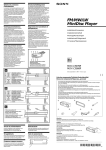
1
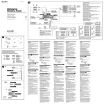
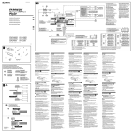
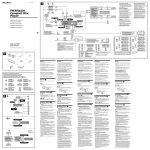
Connection Diagram Schémas de connexion Anschlußdiagramm Schema di collegamento 3-810-606-31 (1) Example 1/Exemple 1/Beispiel 1/Esempio 1 FM/MW/LW Compact Disc Player Front speakers Haut-parleurs avant Frontlautsprecher Diffusori anteriori CDX-3100 Rear speakers Haut-parleurs arrière Hecklautsprecher Diffusori posteriori Installation/Connections Installation/Connexions Example 2/Exemple 2/Beispiel 2/Esempio 2 Installation/Anschluß Front speakers Haut-parleurs avant Frontlautsprecher Diffusori anteriori Installazione/Collegamenti CDX-3100 LINE OUT REAR Power amplifier Amplificateur de puissance Endverstärker Amplificatore di potenza Rear speakers Haut-parleurs arrière Hecklautsprecher Diffusori posteriori Rear speakers Haut-parleurs arrière Hecklautsprecher Diffusori posteriori CDX-3100 Sony Corporation 1996 Printed in Japan Parts for Installation and Connections Pièces de montage et de raccordement Montageteile und Anschlußzubehör Componenti per installazione e collegamenti The numbers in the list are keyed to those in the instructions. Les numéros de la liste correspondent à ceux des instructions. Die Nummern in der Liste sind dieselben wie im Erläuterungstext. I numeri nella lista corrispondono a quelli riportati nelle istruzioni. 1 2 TO 3 P ×1 ×1 ×1 4 5 ×1 ×1 The release key 4 is used for dismounting the unit. See the operating instructions manual for details. La clé de dégagement 4 est nécessaire pour démonter l’appareil. Consulter le mode d’emploi pour plus de détails. Zum Herausnehmen des Geräts wird der Löseschlüssel 4 benötigt. Einzelheiten entnehmen Sie bitte der Bedienungsanleitung. La chiave di rilascio 4 è usata smontare l’apparecchio. Per dettagli, fare riferimento al manuale di istruzioni. Installation Installation Installation Installazione Precautions Précautions Vorsichtsmaßnahmen Precauzioni • Do not tamper with the four holes on the upper surface of the unit. They are for tuner adjustments to be done only by service technicians. • Choose the installation location carefully so that the unit will not hamper the driver during driving. • Avoid installing the unit where it would be subject to high temperatures, such as from direct sunlight or hot air from the heater, or where it would be subject to dust, dirt or excessive vibration. • Use only the supplied mounting hardware for a safe and secure installation. • Ne pas toucher les quatre orifices sur le panneau supérieur de l’appareil. Ils servent aux réglages du tuner qui ne doivent être effectués que par un technicien. • Choisir soigneusement l’emplacement de l’installation, pour que l’appareil ne gêne pas la conduite. • Eviter d’installer l’appareil dans un endroit exposé à des températures élevées, comme en plein soleil ou à proximité d’une bouche d’air chaud, ou à de la poussière, saleté ou vibrations violentes. • Pour garantir un montage sûr, n’utiliser que le matériel fourni. • Nehmen Sie an den vier Öffnungen an der Oberseite des Geräts keine Einstellungen vor. Diese Öffnungen dienen dem Tuner-Abgleich; der Abgleich darf nur von einem Fachmann vorgenommen werden. • Wählen Sie den Einbauort sorgfältig so aus, daß das Gerät die Bedienung des Fahrzeugs nicht behindert. • Bauen Sie das Gerät so ein, daß es keinen hohen Temperaturen (keinem direkten Sonnenlicht, keiner Warmluft von der Heizung), keinem Staub, keinem Schmutz und keinen starken Vibrationen ausgesetzt ist. • Für eine sichere Befestigung verwenden Sie stets nur die mitgelieferten Montageteile. • Non toccare i quattro fori sulla superficie superiore dell’apparecchio. Servono per regolazioni del sintonizzatore che devono essere eseguite solo da tecnici per la manutenzione. • Scegliere con attenzione il luogo di montaggio in modo che l’apparecchio non interferisca con le normali operazioni di guida del conducente. • Evitare di installare l’apparecchio dove sia soggetto ad alte temperature, come da esposizione alla luce solare diretta o al getto di aria calda dell’ impianto di riscaldamento, o dove possa essere soggetto a polvere, sporco e vibrazioni eccessive. • Usare solo il materiale di montaggio in dotazione per un’installazione stabile e sicura. Mounting angle adjustment Réglage de l’angle de montage Adjust the mounting angle to less than 20°. Ajuster l’inclinaison à un angle inférieur à 20°. Hinweis zum Montagewinkel Regolazione dell’angolo di montaggio Das Gerät sollte in einem Winkel von weniger als 20° montiert werden. Regolare l’angolo di montaggio in modo che sia inferiore a 20°. Avant d’installer l’appareil, déposer la façade. Abnehmen und Anbringen der Frontplatte Come staccare e attaccare il pannello anteriore Retrait Nehmen Sie die Frontplatte vor dem Einbau des Geräts ab. Prima di installare l’apparecchio staccare il pannello anteriore. Zum Abnehmen Per staccare Drücken Sie zuerst die Taste OFF, um das Gerät auszuschalten. Lösen Sie dann die Frontplatte durch Drücken der RELEASE-Taste, und ziehen Sie die Frontplatte, wie in der Abbildung gezeigt, ab. Prima di staccare il pannello anteriore, assicurarsi di premere il tasto OFF. Quindi premere il tasto RELEASE per aprire il pannello e staccarlo tirandolo verso di sé come mostrato nell'illustrazione. Zum Anbringen Per attaccare Richten Sie Teil A auf Teil B aus, und drücken Sie die Frontplatte fest, so daß sie mit einem Klicken einrastet. Allineare le parti A e B e spingere il pannello anteriore fino a udire uno scatto. How to Detach and Attach the Front Panel Retrait et pose de la façade Before installing the unit, detach the front panel. Avant de détacher la façade, appuyez sur la touche OFF. Appuyez ensuite sur la touche RELEASE pour ouvrir la façade. Enlevez-la en la tirant vers vous, comme indiqué sur l’illustration. To detach Before detaching the front panel, be sure to press the OFF button first. Then press the RELEASE button to open up the front panel, and detach the panel by pulling it towards you as illustrated. Pose Aligner les points A et B, puis pousser l’appareil jusqu’au déclic. To attach Align the parts A and B, and push the front panel until it clicks. OFF button Touche OFF Taste OFF Tasto di spegnimento To detach Retrait Abnehmen Per staccare To attach Pose Anbringen Per attaccare A B RELEASE button Touche RELEASE RELEASE-Taste Tasto RELEASE Mounting Example Exemple de montage Einbaubeispiel Esempio di montaggio Installation in the dashboard Installation dans le tableau de bord Installation im Armaturenbrett Installazione nel cruscotto 1 182 2 mm 53 m TO P 3 Fire wall Paroi ignifuge Motorraumtrennwand Parete tagliafiamma Dashboard Tableau de bord Armaturenbrett Cruscotto m 2 TO P 1 With the TOP marking up Avec l’inscription TOP vers le haut Mit der TOP-Markierung nach oben hin weisend Con la scritta TOP rivolta verso l’alto Bend these claws, if necessary. Si nécessaire, plier ces griffes. Falls erforderlich, die Klauen hochbiegen. Piegare questi morsetti, se necessario. 3 Connections Connexions Anschluß Collegamenti Caution Précautions Vorsicht Attenzione • This unit is designed for negative ground 12 V DC operation only. • Connect the power connecting cord 5 to the unit and speakers before connecting it to the auxiliary power connector. • Run all ground wires to a common ground point. • Cet appareil est conçu pour fonctionner sur courant continu de 12 V avec masse négative. • Branchez le cordon d'alimention 5 sur l'appareil et les hunt-parleurs avant de le brancher sur le connecteur d'alimentation auxiliaire. • Rassembler tous les fils de terre en un point de masse commun. • Dieses Gerät ist ausschließlich für eine negativ geerdete 12-V-Autobatterie bestimmt. • Verbinden Sie das Netzverbindungskabel 5 mit dem Gerät und den Lautsprechern, bevor Sie es mit dem Hilfsstromanshluß verbinden. • Schließen Sie alle Erdungskabel an einen gemeinsamen Massepunkt an. • Questo apparecchio è stato progettato per l’uso solo a 12 V CC con massa negativa. • Collegare il cavo di collegamento dell'alimentazione 5 all'apparecchio e agli altoparlanti prima di collegarlo al connettore di alimentazione ausiliare. • Portare tutti i cavi di massa a un punto di massa comune. If Your Car has An Accessory Position on the Ignition Key Switch — POWER SELECT Switch Si le contact de votre voiture ne comporte pas de position accessoires Wenn das Zündschloß lhres Autos über eine Zubehörpositiòn verfügt — POWER SELECT-Schalter Se la macchina ha una posizione per accessori sulla chiavetta di accensione To turn the Power Select Function on Press the OFF button while pressing the SEL button. The Power Select Function ties the clock display power to the accessory position on the ignition key switch. To avoid battery wear, the clock is not displayed while the unit is initializing. — Interrupteur POWER SELECT Pour activer la fonction de sélection d'alimentation Appuyez sur la touche OFF tout en maintenant la touche SEL enfoncée. La fonction de sélection d’alimentation relie l’alimentation de l’affichage de l’horloge à la position accessoires de la serrure de contact. Pour éviter l’usure de la batterie, l’horloge n’est pas affichée pendant l’initialisation de l’appareil. So schalten Sie die Power Select-Funktion ein Drücken Sie OFF, und halten Sie dabei SEL gedrückt. Die Power Select-Funktion koppelt die Anzeige der Uhrzeit an die Zubehörposition des Zündschlosses. Das heißt, um eine übermäßige Belastung der Batterie zu vermeiden, wird die Uhrzeit nicht angezeigt, solange sich das Gerät initialisiert. — Interruttore POWER SELECT Per attivare la funzione Power Select Premere il tasto OFF premendo contemporaneamente il tasto SEL. La funzione Power Select associa la visualizzazione dell’ora alla posizione per accessori sulla chiavetta di accensione. Per evitare di consumare le batterie, l’ora non viene visualizzata durante l’inizializzazione dell’apparecchio. Reset Button Touche de réinitialisation Rücksetztaste Pulsante di azzeramento When the installation and connections are over, be sure to press the reset button with a ballpoint pen etc. Quand l’installation et les connexions sont terminées, appuyer sur la touche de réinitialisation avec un stylo bille ou un objet pointu. Nach der Installation und dem Anschluß muß die Rücksetztaste mit einem Kugelschreiber o.ä. gedrückt werden. Dopo avere terminato l’installazione e i collegamenti, assicurarsi di premere il pulsante di azzeramento con la punta di una penna a sfera ecc. Reset button Touche de réinitialisation Rücksetztaste Pulsante di azzeramento Note on the control leads The power antenna control lead (blue) supplies +12 V DC when you turn on the tuner. Remarque sur les fils de contrôle Le fil de contrôle de l’antenne électrique (bleu) fournit du courant continu de +12 V quand le tuner est allumé. Hinweis zu den Steuerleitungen Die (blaue) Motorantennen-Steuerleitung liefert eine Gleichspannung von +12 V, wenn der Tuner eingeschaltet. Nota sui cavi di collegamento Il cavo di controllo dell’antenna automatica (blu) fornisce +12␣ V CC quando si accende il sintonizzatore. Memory hold connection When the yellow power input lead is connected, power will always be supplied to the memory circuit even when the ignition key is turned off. Connexion pour la conservation de la mémoire Lorsque le fil d’entrée d’alimentation jaune est connecté, le circuit de la mémoire est alimenté en permanence même si la clé de contact est sur la position d’arrêt. Zur Stromversorgung des Speichers Wenn das gelbe Stromversorgungskabel angeschlossen ist, wird der Speicher stets (auch bei ausgeschalteter Zündung) mit Strom versorgt. Collegamento per la conservazione della memoria Quando il cavo di ingresso alimentazione giallo è collegato, viene sempre fornita alimentazione al circuito di memoria anche quando la chiavetta di accensione è spenta. Notes on speaker connection • Before connecting the speakers, turn the unit off. • Use speakers with an impedance of 4 to 8 ohms, and with adequate power handling capacities. Otherwise, the speakers may be damaged. • Do not connect the terminals of the speaker system to the car chassis, and do not connect the terminals of the right speaker with those of the left speaker. • Do not attempt to connect the speakers in parallel. • Do not connect any active speakers (with built-in amplifiers) to the speaker terminals of the unit. Doing so may damage the active speakers. Therefore, be sure to connect passive speakers to these terminals. Remarques sur la connexion des haut-parleurs • Avant de raccorder les haut-parleurs, mettre l’appareil hors tension. • Utiliser des haut-parleurs ayant une impédance de 4 à 8 ohms et une capacité adéquate sous peine de les endommager. • Ne pas raccorder les bornes du système de haut-parleurs au châssis de la voiture et ne pas connecter les bornes du hautparleur droit à celles du haut-parleur gauche. • Ne pas tenter de raccorder les haut-parleurs en parallèle. • Ne pas connecter d'enceintes acoustipues actives (avec amplificateurs intégrés) aux bornes d'enceinte de cet appareil, pour éviter d'endommager les enceintes. Veiller à raccorder des enceintes passires. Note sul collegamento dei diffusori • Prima di collegare i diffusori spegnere l’apparecchio. • Usare diffusori di impedenza compresa tra 4 e 8 ohm e con capacità di potenza adeguata, altrimenti i diffusori possono essere danneggiati. • Non collegare i terminali del sistema diffusori al telaio dell’auto e non collegare i terminali del diffusore destro a quelli del diffusore sinistro. • Non collegare i diffusori in parallelo. • Non collegare alcun diffusore attivo (con amplificatore incorporato) ai terminali diffusori dell’apparecchio perché questo può danneggiare i diffusori attivi. Assicurarsi di collegare diffusori passivi a questi terminali. Warning If you have a power antenna without a relay box, connecting this unit with the supplied power connecting cord 5 may damage the antenna. Avertissment Si vous disposez d'une antenne électrique sans boîtier de relais, le branchement de cet appareil au moyen du cordon d'alimentation fourni 5 risque d'endommager l'antenne. Hinweise zum Lautsprecheranschluß • Schalten Sie das Gerät aus, bevor Sie die Lautsprecher anschließen. • Verwenden Sie Lautsprecher mit einer Impedanz zwischen 4 und 8 Ohm und ausreichender Belastbarkeit. Ansonsten können die Lautsprecher beschädigt werden. • Verbinden Sie die Lautsprecheranschlüsse nicht mit dem Wagenchassis, und verbinden Sie auch nicht die Anschlüsse des rechten mit denen des linken Lautsprechers. • Versuchen Sie nicht, Lautsprecher parallel anzuschließen. • An die Lautsprecheranschlüsse dieses Geräts dürfen nur Passivlautsprecher angeschlossen werden. Schließen Sie keine Aktivlautsprecher (Lautsprecher mit eingebauten Verstärkern) an, da diese sonst beschädigt werden können. Warnung Wenn Sie eine Motorantenne ohne Relaiskästchen verwenden, kann durch Anschließen dieses Geräts mit Hilfs des mitgelieferten Netzverbindungskabels 5 die Antenne beschädigt werden. Avvertenza Se l'antenna che collega l'apparecchio al cavo di alimentazione in dotazione 5 non ha la scatola di relè l'antenna, si può danneggiare. Connection Example Connexions de l’exemple Anschlußbeispiel Esempi di Collegamento Rear speakers Haut-parleurs arrière Hecklautsprecher Diffusori posteriori LINE OUT REAR from car antenna de l’antenne de la voiture von Autoantenne dall’antenna dell’auto Fuse (15 A) Fusible (15 A) Sicherung (15 A) Fusibile (15 A) Power amplifier Amplificateur de puissance Endverstärker Amplificatore di potenza 5 RCA pin cord (RC-63 (1 m), RC-64 (2 m) or RC-65 (5 m)) (not supplied) Cordon à broche RCA (RC-63 (1 m), RC-64 (2 m) ou RC-65 (5 m)) (non fourni) RCA-Kabel (RC-63 (1 m), RC-64 (2 m) oder RC-65 (5 m)) (nicht mitgeliefert) Cavo a terminali RCA (RC-63 (1 m), RC-64 (2 m) o RC-65 (5 m)) (non in dotazione) Blue/white striped Rayé bleu/blanc Blau-weiß gestreift Astrisce blu e bianche WARNING Auxiliary power connectors may vary depending on the car. Be sure to check the power connection diagram sheet supplied with the unit. Improper connections may damage your car. If the supplied power connecting cord can not be used with your car, consult your nearest Sony dealer. AMP REM Max. supply current 0.3 A Courant max. fourni 0,3 A max. Versorgungsstrom 0,3 A Alimentazione massima fornita 0,3 A AVERTISSEMENT Le connecteur d’alimentation auxiliaire peut varier suivant le type de voiture. Vérifiez le schéma du connexion d’alimentation furni avec l’appareil. Un raccordement incorrect risque d’occasionner des dommages à votre voiture. Si le cordon d'alimentation fourni ne peut être utilisé avec votre voiture, consultez votre revendeur Sony. VORSICHT Die Hilfsstromanschlüsse können je nach Fahrzeugtyp unterschiedlich sein. Sehen Sie im Hilfsstromanschlußdiagramm für Ihr Fahrzeug nach, wie die Verbindungen ordnungsgemäß vorgenommen werden müssen. Fehlerhafte Verbindungen können zu Schäden an Ihrem Fahrzeug führen. Wenn das mitgeliferte Netzverbindungskabel nicht für den Einsatz in Ihrem Fahrzeug geeignet ist, wenden Sie sich bitte an lhren Sony-Händler. Attenzione Il connettore di alimentazione ausiliare può variare a seconda del tipo di macchina. Controllare il foglio con il diagramma del connettore di alimentazione in dotazione con l’apparecchio, connessioni non corrette potrebbero danneggiare la macchina. Se il cave di collegamento dell'alimentazione in dotazione non pu essere utilizzato con la vostra auto, consultare il revenditore Sony pi ù vicino. to the car’s auxiliary power connector vers un connecteur d’alimentation auxiliaire de la voiture an Hilfsstromanschluß des Autos al connettore di alimentazione ausiliare dell’auto to the car’s speaker connector vers un connecteur de haut-parleur de la voiture an Lautsprecheranschluß des Autos a un connettore dell'altoparlante dell’auto 7 5 8 6 Pin Colour Broche Couleur Stift Farbe Colore Pin 3 1 4 2 Function Fonction Funktion Funzione 4 Yellow Jaune Gelb Giallo continuous power supply alimentation continue permanente Stromversorgung alimentazione continua 5 Blue Bleu Blau Blu power antenna control antenne électrique elektronische Antenne antenna elettrica Positions 1, 2, 3 and 6 do not have pins. Les positions 1, 2, 3 et 6 ne comportent pas de broche. An Position 1, 2, 3 und 6 befinden sich keine Stifte. Le posizioni 1, 2, 3 e 6 non hanno pin. 1 3 5 7 1 3 5 7 2 4 6 8 2 4 6 8 Pin Colour Broche Couleur Stift Farbe Pin Colore Function Fonction Funktion Funzione 7 Red Rouge Rot Rosso switched power supply alimentation commutée geschaltete Stromversorgung alimentazione a scatto 8 Black Noir Schwarz Nero ground masse Masse terra Colour Pin Broche Couleur Farbe Stift Colore Pin 1 Purple Mauve Violett Viola 7 5 8 6 3 4 2 Function Fonction Funktion Funzione +; Speaker, Rear, Right +; haut-parleur, arrière, droit +; Lautsprecher hinten rechts +; Altoparlante, posteriore, destro 2 –; Speaker, Rear, Right –; haut-parleur, arrière, droit –; Lautsprecher hinten rechts –; Altoparlante, posteriore, destro 3 +; Speaker, Front, Right +; haut-parleur, avant, droit +; Lautsprecher vorne rechts +; Altoparlante, anteriore, destro 4 Grey Gris Grau Grigio 1 –; Speaker, Front, Right –; haut-parleur, avant, droit –; Lautsprecher vorne rechts –; Altoparlante, anteriore, destro Pin Colour Broche Couleur Stift Farbe Pin Colore 5 White Blanc Weiß Blanco Function Fonction Funktion Funzione +; Speaker, Front, Left +; haut-parleur, avant, gauche +; Lautsprecher vorne links +; Altoparlante, anteriore, sinistro 6 –; Speaker, Front, Left –; haut-parleur, avant, gauche –; Lautsprecher vorne links –; Altoparlante, anteriore, sinistro 7 +; Speaker, Rear, Left +; haut-parleur, arrière, gauche +; Lautsprecher hinten links +; Altoparlante, posteriore, sinistro Green Vert Grün Verde 8 Negative polarity positions 2, 4, 6, and 8 have striped cords. Les positions de polarité négative 2, 4, 6 et 8 sont dotées de cordons rayés. An den negativ gepolten Positionen (2, 4, 6 und 8) befinden sich farbige Adern. Le posizioni a polatità negativa 2, 4, 6 e 8 hanno cavi spelati. –; Speaker, Rear, Left –; haut-parleur, arrière, gauche –; Lautsprecher hinten links –; Altoparlante, posteriore, sinistro