1
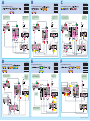
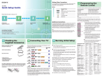
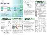
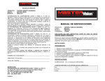
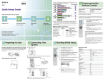
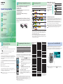
2-654-475-11 (1)
1
KLV-S40A10
Quick Setup Guide
Please follow the steps to setup your TV:
Checking the
Supplied Accessories
zzz
1
zzz
2
Connecting Your TV
(See reverse side)
• Remote control (RM-YA001) (1) and size AA batteries (2)
• 75-ohm coaxial cable (ferrite core attached) (1)
• AC power cord (1)
• HD15-HD15 cable (1)
• Support belt (1), securing screw (1) and wood screw (1)
• Operating Instructions (1)
• Quick Setup Guide (1)
• Leaflet (Installing the Wall-Mount Bracket) (1)
• Warranty Card (1)
Connecting Your TV
•Review the following chart to determine which diagram to use to
connect the components in your system:
For these components
4
See reverse side
A
or
Your TV includes
several types of video
inputs. Use the inputs
that are available on
your components that
provide the best
video performance, as
shown in the table on
the right.
Best Video
Performance
Connector type
HDMI*
(High-Definition
Multimedia Interface)
Component video*
S VIDEO
Composite video
RF/Coaxial
B
C
D
or
Inserting Batteries into the Remote Control
Insert two size AA batteries (supplied) by matching the e and E on
the batteries to the diagram inside the remote control’s battery
compartment.
or
Running Initial
Setup
E
or
zzz
3
2
Checking the Supplied Accessories
Making Video Connections
F
or
Programming
the Remote Control
* Support 480i, 480p, 720p, 1080i
Additional Connections
For best audio performance, connect your digital audio components
using either digital optical or digital coaxial audio connections.
Depending on which components are in your system, you may need
to complete additional connections. For example, if you have a
satellite receiver, you’ll need to connect the satellite antenna. If you
have an A/V receiver, you’ll need to connect speakers.
The connection diagrams shown on the reverse side are recommendations only; other
possible solutions may exist. Connections that include an A/V receiver can often be
very complex, so check your A/V receiver’s instruction manual for additional details.
See the Operating Instructions when connecting to a personal computer.
•See the “Cables Required” chart that appears with the diagram to
determine which cables you’ll need. You may need to purchase
extra accessories, such as cables and splitters, depending on the
components you plan to connect.
•Turn off and unplug all components before making connections.
•If you are connecting a digital cable box, you’ll need a special bidirectional splitter that’s compatible with your cable box. Contact
your cable provider for details.
If your product is not working properly
DO NOT RETURN TO THE STORE.
For service and technical assistance
Call our Customer Information Service Center (Toll Free):
1-877-899-SONY (7669) for Canadian residents.
Sony Corporation © 2005 Printed in Japan
3
1
2
Running Initial Setup
Press POWER to turn on the TV.
The Initial Setup screen appears.
Press V or v to select the on-screen display language. Then press
.
The message “First please connect cable/antenna” appears.
By default, Auto Program is set to scan cable TV channels.
3
Press CH+ to start Auto Program.
Auto Program automatically creates a list of receivable channels.
When finished, the lowest numbered channel is displayed. When all
the receivable channels are stored, the “Show/Hide Channels”
settings appear.
Manufacturer’s Codes
4
Programming the Remote Control
The remote control is preset to operate Sony brand video equipment.
Sony Equipment
DVD/VCR
601 (Sony Dream System)
SAT/Cable
801 (Sony Satellite Receiver)
Follow the steps below to program your TV’s remote control to
operate the other video equipment.
Using the code list on the right, find the three-digit code number for
the manufacturer of your equipment. (If more than one code number
is listed, use the number listed first.)
1
MTS/ POWER
MUTING DISPLAY SAP
POWER
SAVING FREEZE
TV/
VIDEO
To scan available VHF/UHF antenna channels instead of the cable
TV channels
1
2
3
1
2
3
FUNCTION
F1
F2
To perform Auto Program again, follow the above instructions.
Depending on your signal source, be sure to set Cable to On or Off
accordingly (see Operating Instructions).
TOP MENU MENU
GUIDE
SLEEP
1
Enter the three-digit manufacturer’s code number
using the --9 buttons while the button is lit,
approximately 10 seconds.
Press button.
When the programming is correct, the selected
FUNCTION button will flash twice slowly, and
when not, flashes five times quickly.
To check if the code works
MODE
The Initial Setup menu will appear each time the TV is turned on until you complete the
scanning for the available channels.
2
RETURN WEGA GATE
Set Cable to Off.
Start Auto Program by pressing CH+.
Press and hold the
or
FUNCTION button
you want to program on the remote control and
press the
button simultaneously. The selected
FUNCTION button (DVD/VCR or SAT/CABLE)
will flash.
DISPLAY
3
Select Settings in WEGA GATE, then go to Channels settings.
Programmable Code Number
SOUND PICTURE WIDE
TV/SAT
Aim your TV’s remote control at the equipment, and
press the green POWER button. If the equipment
responds, the programming is completed. If not, try the
next code listed.
If no code is input within the above specified time, or an invalid or incorrect code
number is input, the remote control automatically goes back to the previous setting.
In some cases, you may not be able to program your remote control to operate other
equipment. In such cases, use the equipment’s own remote control.
Dead batteries or removing the batteries may cause the programmable codes to be lost
and revert back to factory settings.
Reprogramming the codes may be necessary.
DVD Players
Manufacturer
Code
Manufacturer
Code
Aiwa*
338, 344
Scott
Audio Dynamic
314, 337
312, 313, 321, 335,
323, 324, 325, 326
319, 317
Sharp
327, 328
Manufacturer
Code
Broksonic
Sony
751
Canon
309, 308
Signature 2000 (M.Ward) 338, 327
General Electric
755
Citizen
332
SV 2000
Hitachi
758
Craig
302, 332
Sylvania
308, 309, 338, 310
JVC
756
Curtis Mathes
304, 338, 309
Symphonic
338
Magnavox
757
Daewoo
341, 312, 309
Tashiro
332
Mitsubishi
761
DBX
314, 336, 337
Tatung
314, 336, 337
Panasonic
753
Dimensia
304
Teac
314, 336, 338, 337
Philips
757
Emerson
309, 308
752
319, 320, 316, 317,
318, 341
Technics
Pioneer
Toshiba
312, 311
Fisher
330, 335
Wards
Funai
338
327, 328, 335, 331,
332
RCA/PROSCAN
755
Samsung
758
Toshiba
754
Zenith
760
DVD Changers
Manufacturer
Code
Sony
765
Panasonic
766
DVD/VCR Combo Units
338
General Electric
329, 304, 309
Yamaha
314, 330, 336, 337
Go Video
322, 339, 340
Zenith
331
Goldstar
332
Hitachi
306, 304, 305, 338
Cable Boxes
Instant Replay
309, 308
Manufacturer
Code
JC Penney
309, 305, 304, 330,
314, 336, 337
Sony
230
Hamlin/Regal
222, 223, 224, 225,
226
JVC
314, 336, 337, 345,
346, 347
201, 202, 203, 204,
205, 206, 207, 208,
218, 222
227, 228, 229
Kenwood
314, 336, 332, 337
LG
332
LXI (SEARS)
332, 305, 330, 335,
338
Oak
Panasonic
219, 220, 221
308, 309, 310
Pioneer
214, 215
209, 210, 211
Code
Sony
767
Zenith
768
Magnavox
Toshiba
773
Marantz
314, 336, 337
Scientific Atlanta
Samsung
774
Marta
332
Tocom
216, 217
JVC
775
Memorex
309, 335
Zenith
212, 213
Broksonic
776
Minolta
305, 304
Panasonic
777
Mitsubishi/MGA
323, 324, 325, 326
Multitech
325, 338, 321
NEC
314, 336, 337
Olympic
309, 308
Manufacturer
Code
Sony
770, 771, 772
5.1ch DVD AV System
Optimus
327
Orion
317
Panasonic
308, 309, 306, 307
Pentax
305, 304
Manufacturer
Code
Philco
308, 309
Sony (DAV)
601, 602, 603, 604
Philips
308, 309, 310
Pioneer
308
Quasar
308, 309, 306
AV Receivers
Manufacturer
Code
Sony
764
RCA/PROSCAN
Realistic
VCRs
Manufacturer
Code
Sony
301, 302, 303
Admiral (M. Ward)
327
304, 305, 308, 309,
311, 312, 313, 310,
329
314
Samsung
322, 313, 321
Sanyo
330, 335
WEGA GATE
Favorites
TV List
External Inputs
Settings
Show your Favorite Channels
Set:
Exit:
WEGA GATE
Satellite Receivers
Manufacturer
Code
Sony
801
Dish Network
810
Echostar
810
General Electric
802
Hitachi
805
Hughes
804
Mitsubishi
809
Panasonic
803
RCA/PROSCAN
802, 808
Toshiba
806, 807
Philips
811
Samsung
812
309, 330, 328, 335,
324, 338
Sansui
The WEGA GATE button on your remote control is a new feature
that allows you to easily navigate to the most convenient TV
functions such as Favorite Channels, TV Channel List, External Input
list or Settings. The TV’s main menu is found under Settings.
Select:
Jerrold/G.I./
Motorola
Manufacturer
HDD/DVD Combo Units
Enjoy your new TV with WEGA GATE
* If an Aiwa VCR does not
work even though you enter
the code for Aiwa, enter the
code for Sony instead.
To adjust Settings related to Video, Audio, Screen, Channel, Parent (V-chip), Clock/
Timers or to set up certain features on your TV, press
then select “Settings” on the
WEGA GATE control panel.
WEGA GATE
A
Cables Required
Splitter
Coaxial
Composite
Component
Audio
Use this diagram if you have;
or
If your DVD player or satellite
receiver has an HDMI jack, use that
instead of the video connections
shown here.
1
4
2
1
1
If you are not using a cable box
or satellite receiver, connect
your cable or antenna to the
VCR’s RF IN jack.
B
Cables Required
Splitter
Coaxial
Composite
Component
Audio
Use this diagram if you have;
or
If you are not using a cable box
or satellite receiver, connect
your cable or antenna to the
VCR’s RF IN jack.
If your DVD player or satellite
receiver has an HDMI jack, use that
instead of the video connections
shown here.
Cables Required
Splitter
Coaxial
Composite
Component
HDMI
Audio
Use this diagram if you have;
The DVI-HDTV VIDEO connector does
not provide audio, so audio cables
must be connected to provide sound
when a DVI to HDMI adaptor is used.
Splitter
Cable
Right side
of TV
Rear of TV
Splitter
DVD Player
DVD Player
Splitter
Rear of TV
Y
S VIDEO
VIDEO
L
(MONO)
1
Cable Box or
Satellite Receiver*
L
R
R
3
VIDEO IN
PC
AUDIO
IN
Y
L
PB
S VIDEO
S VIDEO
AUDIO AUDIO
R
PC IN
6 (RGB IN)
PB
PR
IN
4
HD/DVD IN
AUDIO
(1080i/720p/480p/480i) OUT
Cable Box or
Satellite Receiver*
PB
VIDEO
PR
L
(MONO)
L
IN
5
R
1
PR
L
(MONO)
L
Cable Box
L
R
R
1
IN
3
VIDEO IN
L
Do not connect
a PC to the TV’s
HDMI input.
OUT
R
R
3
VIDEO IN
VHF/UHF
VIDEO
AUDIO AUDIO
AUDIO AUDIO
OUT
PC
AUDIO
IN
Y
Rear of TV
PC
AUDIO
IN
1
6
3
1
1
1
If you are not using a
cable box, connect your
cable or antenna to the
VCR’s RF IN jack.
Cable
Cable
DVD Player
1
4
3
1
2
C
4
HD/DVD IN
AUDIO
(1080i/720p/480p/480i) OUT
R
4
HD/DVD IN
AUDIO
(1080i/720p/480p/480i) OUT
IN
OUT
L
AUDIO IN
VHF/UHF
R
VHF/UHF
VCR
A / V Receiver
INPUT
DVD
TV
VIDEO
LINE IN
IN
VCR
VCR
LINE IN
IN
L
LINE OUT
OUT
R
L
AUDIO
LINE IN
R
VIDEO
Satellite Receiver
VCR
VIDEO
OUT
AUDIO
OUT
CABLE IN
ANT IN
SAT IN
OUT TO TV
LINE OUT
OUT
R
L
AUDIO
LINE IN
IN
LINE OUT
R
L
AUDIO
LINE OUT
VIDEO
OUT
VIDEO
R
L
AUDIO
VIDEO
Satellite
Antenna
Cable
D
Cables Required
Splitter
Coaxial
Composite
Component
Audio
Use this diagram if you have;
or
If your DVD player or satellite receiver
has an HDMI jack, use that instead of
the video connections shown here.
Cable
1
3
3
1
2
If you are not using
a cable box or
satellite receiver,
connect your cable
or antenna to the
VCR’s RF IN jack.
E
Cables Required
Splitter
Coaxial
Composite
Component
HDMI
Audio
Use this diagram if you have;
or
The DVI-HDTV VIDEO connector does
not provide audio, so audio cables
must be connected to provide sound
when a DVI to HDMI adaptor is used.
1
3
2
1
1
1
F
Cables Required
Splitter
1
Coaxial
4
Composite
2
Composite
1
(without Audio)
Component 1
Use this diagram if you have;
or
If your cable box has a
DVI jack, use that instead
of the video connections
shown here.
If you are not using a cable
box or satellite receiver,
connect your cable or
antenna to the VCR’s RF IN
jack.
Cable
Cable
Splitter
DVD Player
DVD Player
Rear of TV
Y
S VIDEO
VIDEO
L
(MONO)
PC
AUDIO
IN
PB
Y
Cable Box or
Satellite Receiver*
PR
L
L
S VIDEO
VIDEO
R
R
1
3
VIDEO IN
4
HD/DVD IN
AUDIO
(1080i/720p/480p/480i) OUT
VHF/UHF
IN
IN
VIDEO 1
L
(MONO)
5
AUDIO OUT
L
VIDEO 2
VIDEO OUT
AUDIO IN
L
R
MONITOR OUT
VIDEO IN
Y
Do not connect
a PC to the TV’s
HDMI input.
HD Cable Box or
HD Satellite Receiver*
PR
L
L
R
L
AUDIO IN
S VIDEO
VIDEO IN
Y
PB/CB
3
VIDEO IN
R
4
HD/DVD IN
AUDIO
(1080i/720p/480p/480i) OUT
PB
PR/CR
COMPONENT VIDEO OUT
S VIDEO
IN
R
R
1
PC
AUDIO
IN
PB
AUDIO AUDIO
OUT
Splitter
Rear
of TV
Sony Dream System
PC
AUDIO
IN
R
PC IN
6 (RGB IN)
AUDIO AUDIO
R
Splitter
Right side
of TV
Rear of TV
VIDEO
PR
L
(MONO)
L
Cable Box or
Satellite Receiver*
L
AUDIO AUDIO
R
R
OUT
1
3
VIDEO IN
L
R
4
HD/DVD IN
AUDIO
(1080i/720p/480p/480i) OUT
IN
OUT
AUDIO IN
R
VHF/UHF
VHF/UHF
Digital Recorder
LINE IN
IN
L
R
LINE OUT
OUT
AUDIO
VIDEO
VCR
VCR
A/V
Receiver
INPUT
DVD
VCR
LINE IN
IN
LINE OUT
TV
VIDEO
L
LINE IN
R
VIDEO
OUT
OUT
R
L
AUDIO
LINE OUT
OUT
AUDIO
OUT
If your DVD player or satellite receiver
has an HDMI jack, use that instead of
the video connections shown here.
LINE IN
IN
VIDEO
R
L
AUDIO
VIDEO
* Satelite Antenna Cable not shown.