1
A-CEE-100-21(1)
Color Camera Module
Technical Manual
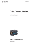
FCB-PV10
2006 Sony Corporation
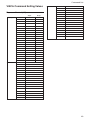
Table of Contents
Features ..................................................................... 3
Precautions ................................................................ 4
Locations of Controls ............................................... 5
Basic Functions ......................................................... 6
Overview of Functions ................................................ 6
Eclipse ...................................................................... 27
Spectral Sensitivity Characteristics .......................... 27
Vibration Specifications ............................................ 27
Initial Settings, Custom Preset and Backup ............. 28
Mode Condition ........................................................ 30
Command List ......................................................... 33
VISCA/RS-232C Commands ................................... 33
FCB Camera Commands ......................................... 39
Specifications .......................................................... 53
2
Overview
Features
• The FCB camera is equipped with a CCD which
adopts the all-pixel read-out method for all 330,000
effective picture elements “progressive scan” and the
primary color filter, enabling use of square pixels.
The adoption of this type of CCD enables the high
resolution and high color reproduction of this camera.
Thus, this is an ideal camera for use in capturing
digital images.
• 10× optical zoom.
• Digital data output, supporting three output modes.
– 16-bit PS output mode, 8-bit PS output mode and
8-bit interlace output mode (Substantially
comparable to ITU-R BT601 and ITU-R BT656.)
• Spherical Privacy Zone Masking function which
corresponding to 3 dimensions.
– Enabling mosaic masking.
• E-FLIP function
• Slow shutter mode (max 1 sec)
• VISCA is a communications protocol, which enables
the camera to be controlled remotely by commands
from a host computer/controller. Also, high
communication speeds are available (19200 bps and
38400 bps).
With consideration given to environmental
protection, this module is designed to operate with
low power consumption and also incorporates leadfree and halogen-free circuit boards.
3
Overview
Precautions
Software
Use of the demonstration software developed by Sony
Corporation or use of the software with customer
developed application software may damage hardware,
the application program or the camera. Sony
Corporation is not liable for any damages under these
conditions.
Operation
Start the camera control software on your computer
after you turn on the camera and the image is
displayed.
Operation and Storage Locations
Do not shoot images that are extremely bright (e.g.,
light sources, the sun, etc.) for long periods of time. Do
not use or store the camera in the following extreme
conditions:
• Extremely hot or cold places (operating temperature
0 ˚C to +40 ˚C (32 ˚F to 104 ˚F))
• Close to generators of powerful electromagnetic
radiation such as radio or TV transmitters
• Where it is subject to fluorescent light reflections
• Where it is subject to unstable (flickering, etc.)
lighting conditions
• Where it is subject to strong vibration
Care of the Unit
In case of abnormal operation, contact your authorized
Sony dealer or the store where you purchased the
product.
Phenomena specific to CCD image
sensors
The following phenomena that may appear in images
are specific to CCD (Charge Coupled Device) image
sensors. They do not indicate malfunctions.
White flecks
Although the CCD image sensors are produced with
high-precision technologies, fine white flecks may be
generated on the screen in rare cases, caused by cosmic
rays, etc.
This is related to the principle of CCD image sensors
and is not a malfunction.
The white flecks especially tend to be seen in the
following cases:
• when operating at a high environmental temperature
• when you have raised the master gain (sensitivity)
• when operating in Slow-Shutter mode
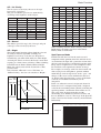
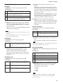
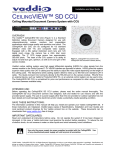
Vertical smear
When an extremely bright object, such as a strong
spotlight or flashlight, is being shot, vertical tails may
be produced on the screen, or the image may be
distorted.
Monitor screen
Vertical tails shown on the
image.
Remove dust or dirt on the surface of the lens with a
blower (commercially available).
Other
Do not apply excessive voltage. (Use only the
specified voltage.) Otherwise, you may get an electric
shock or a fire may occur.
Bright object
(e.g. strong spotlight,
strong reflected light,
flashlight, the sun)
Aliasing
When fine patterns, stripes, or lines are shot, they may
appear jagged or flicker.
4
Locations of Controls
Front
Right side
Bottom
1 Lens
2 CN701 connector
3 CN501 connector
4 S501 Switch
Used to change the output mode between 16-bit and
8-bit output modes.
5 Tripod screw holes
When a tripod is used, please use 10 mm (13/32 in.)
screws to attach it to the camera. Also, please be sure
to attach the tripod securely.
5
Basic Functions
Basic Functions
Overview of Functions
VISCA commands are the basis of camera control.
Timing Chart
As VISCA Command processing can only be carried
out one time in a Vertical cycle, it takes the maximum
1V cycle time for an ACK/Completion to be returned.
If the Command ACK/Completion communication
time can be cut shorter than the1V cycle time, then
every 1V cycle can receive a Command.
General Commands
Commands
• Power On/Off
Powers the camera on and off. When the power is off,
the camera is able to accept only the lowest level of
VISCA Commands; the display and other features are
turned off.
• I/F clear
Clears the Command buffer of the FCB camera.
Clearing the buffer can also be carried out from the
control application software when the power is on.
• Address set
VISCA is a protocol, which normally can support a
daisy chain of up to seven attached devices.
However, the FCB camera does not support camera
connections in a daisy chain. Therefore, whenever a
camera is connected for the first time, be sure to use
the address set to confirm the address.
• ID Write
Sets the camera ID.
• Mute
Blanks the screen and sends out a synchronizing
signal.
Within
Query Commands
• Lens Initialization
Initializes the zoom and focus of the lens. Even when
power is already on, it initializes the zoom and the
focus.
Within
16 Byte
6
Basic Functions
Zoom
The FCB camera employs an 10× optical zoom lens.
Lens specifications: Optical 10×, f = 4.2 to 42 mm
(F1.8 to F2.9)
The horizontal angle of view is approximately 46
degrees (wide end) to 4.6 degrees (tele end).
You can activate the zoom in the following two ways:
• By pressing the TELE or WIDE buttons on the
camera itself.
• Using a VISCA Command
Using Standard Mode
Using Variable Mode
There are eight levels of zoom speed.
Direct Mode
Setting the zoom position enables quick
movement to the designated position.
In these standard and variable Speed Modes, it is necessary
to send a “Stop Command” to stop the zoom operation.
Focus
Focus has the following modes, all of which can be set
using VISCA Commands.
• Auto Focus Mode
The minimum focus distance is 10 mm at the optical
wide end and 1000 mm at the optical tele end
(distance from the front end of the lens), and is
independent of the digital zoom.
The AutoFocus (AF) function automatically adjusts
the focus position to maximize the high frequency
content of the picture in a center measurement area,
taking into consideration the high luminance and
strong contrast components.
AF sensitivity can be set to either Normal or LOW.
- Normal
Reaches the highest focus speed quickly. Use this
when shooting a subject that moves frequently.
Usually, this is the most appropriate mode.
- LOW
Improves the stability of the focus. When the
lighting level is low, the AF function does not take
effect, even though the brightness varies,
contributing to a stable image.
• Manual Focus Mode
Manual Focus has both a Standard Speed Mode and a
Variable Speed Mode. Standard Speed Mode focuses
at a fixed rate of speed. Variable Speed Mode has
eight speed levels that can be set using a VISCA
Command.
In these standard and variable Speed Modes, it is necessary to
send a “Stop Command” to stop the zoom operation.
• One Push Trigger Mode
When a Trigger Command is received, the lens
moves to adjust the focus for the subject. The focus
lens then holds the same position until the next
Trigger Command is input.
• Infinity Mode
The lens is forcibly moved to a position suitable for
an unlimited distance.
• Near Limit Mode
Can be set in a range from 1000 (∞) to C000 (10 mm).
The focus range is narrowed by excluding the
unnecessary range.
- Normal AF Mode
This is the normal mode for AF operations.
- Interval AF Mode
The mode used for AF movements carried out at
defined intervals. The time intervals for AF
movements and for the timing of the stops can be
set in one-second increments using the Set Time
Command. The initial value for both is set to five
seconds.
- Zoom Trigger Mode
When the zoom is changed with the TELE or the
WIDE buttons, the pre-set value (initially set at 5
seconds) becomes that for AF Mode. Then, it
returns to Manual Focus mode.
7
Basic Functions
White Balance
White Balance has the following modes, all of which
can be set using VISCA Commands.
• Auto White Balance
Auto white balance obtains the proper color
reproduction by automatically adjusting white
balance to ensure a white object always looks white.
This function computes the white balance value
output using color information from the entire screen.
It outputs the proper value using a pre-set value for a
color temperature radiating from a black subject
based on a rage of values from 2000 to 10000K.
This mode is the default setting.
Note
When the light source suddenly changes from the light
source available when the FCB camera was turned on, the
proper color reproduction may not be obtained because the
system cannot compensate the sudden change of color
temperature.
• ATW
Auto Tracing White balance (2000 to 10000 K)
• Indoor
3200 K Base Mode
• Outdoor
5800 K Base Mode
• One Push WB
The One Push White Balance mode is a fixed white
balance mode that may be automatically readjusted
only at the request of the user (One Push Trigger),
assuming that a white subject, in correct lighting
conditions and occupying more than 1/2 of the image,
is submitted to the camera.
One Push White Balance data is lost when the power
is turned off. If the power is turned off, reset the One
Push White Balance.
• Manual WB
Manual control of R and B gain, 256 steps each
Automatic Exposure Mode
The variety of AE functions, which allow video signal
to output the optimum image for subjects from low
light conditions to bright light conditions, are
available.
• Full Auto
Auto Iris and Gain, Fixed Shutter Speed (1/30 s)
• Iris Priority
Variable Iris (F1.8 to Close, 18 steps), Auto Gain and
Shutter speed.
• Manual
Variable Shutter, Iris and Gain.
• Bright
Variable Iris and Gain (Close to F2.0, 17 steps at
0 dB: F1.8, 15 steps from 0 to 28 dB)
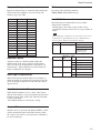
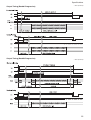
AE – Shutter Priority
The shutter speed can be set freely by the user to a
total of 22 steps – 16 high speeds and 6 low speeds.
When the slow shutter is set, the speed can be 1/30,
1
/15, 1/8, or 1/4 s. The picture output is read at a normal
rate from the memory. The memory is updated at a low
rate from the CCD. AF capability is low.
In high speed mode, the shutter speed can be set up to
1
/10,000 s. The iris and gain are set automatically,
according to the brightness of the subject.
Data
15
14
13
12
11
10
0F
0E
0D
0C
0B
0A
09
08
07
06
05
04
03
02
01
00 a)
30fps
10000
6000
4000
3000
2000
1500
1000
725
500
350
250
180
125
100
90
60
30
15
8
4
2
1
25fps
10000
6000
3500
2500
1750
1250
1000
600
425
300
215
150
120
100
75
50
25
12
6
3
2
1
a) For AE-Manual only.
Note
When the shutter speed 1/1 s or 1/2 s is used, Auto Focus
and White Balance may not function fully.
• Shutter Priority
Variable Shutter Speed, Auto Iris and Gain
(1/1 to 1/10,000 s, 22 steps, std. shutter: 16 steps, slow
shutter: 6 steps)
8
Basic Functions
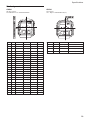
AE – Iris Priority
The iris can be set freely by the user to 18 steps
between F1.8 and Close.
The gain and shutter speed are set automatically
according to the brightness of the subject.
Data
11
10
0F
0E
0D
0C
0B
0A
09
Setting value
F1.8
F2.0
F2.4
F2.8
F3.4
F4.0
F4.8
F5.6
F6.8
Data
08
07
06
05
04
03
02
01
00
Setting value
F8
F9.6
F11
F14
F16
F19
F22
F28
CLOSE
AE – Manual
The shutter speed (22 steps), iris (18 steps) and gain
(16 steps) can be set freely by the user.
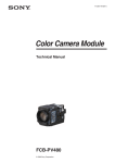
AE – Bright
The bright control function adjusts both the gain and
iris using an internal algorithm according to a
brightness level freely set by the user. Exposure is
controlled by gain when dark and by iris when bright.
As both gain and iris are fixed, this mode is used when
exposing at a fixed camera sensitivity. When switching
from Full Auto or Shutter Priority Mode to Bright
Mode, the current status will be retained for a short
period of time.
Only when the AE mode is set to “Full Auto” or
“Shutter Priority,” the user can switch it to “Bright.”
Gain
IRIS AGC
OPEN MAX
IRIS curve
Gain curve
CLOSE MIN
Dark
Bright
Controlled
by gain
Controlled by IRIS
Data
Iris
Gain
Data
Iris
Gain
1F
F1.8
28 dB
0F
F2.4
0 dB
1E
F1.8
26 dB
0E
F2.8
0 dB
1D
F1.8
24 dB
0D
F3.4
0 dB
1C
F1.8
22 dB
0C
F4.0
0 dB
1B
F1.8
20 dB
0B
F4.8
0 dB
1A
F1.8
18 dB
0A
F5.6
0 dB
19
F1.8
16 dB
09
F6.8
0 dB
18
F1.8
14 dB
08
F8.0
0 dB
17
F1.8
12 dB
07
F9.6
0 dB
16
F1.8
10 dB
06
F11
0 dB
15
F1.8
8 dB
05
F14
0 dB
14
F1.8
6 dB
04
F16
0 dB
13
F1.8
4 dB
03
F19
0 dB
12
F1.8
2 dB
02
F22
0 dB
11
F1.8
0 dB
01
F28
0 dB
10
F2.0
0 dB
00
CLOSE
0 dB
When switching from the Shutter Priority mode to the
Bright mode, the shutter speed set in the Shutter
Priority mode is maintained.
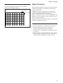
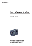
Spot Exposure Mode
In Full Auto AE, the level for the entire screen is
computed and the optimum Auto Iris and Gain levels
are determined. In Spot AE, a particular section of the
subject can be designated, and then that portion of the
image can be weighted and a value computed so that
Iris and Gain can be optimized to obtain an image.
For example, in an image with a lot of movement and
with varying levels of brightness, portions without
much change can be designated as such a “spot,” and
changes to the screen can be minimized in that area.
As shown in the diagram below, a range of 16 blocks
vertically and 16 blocks horizontally can be
designated.
In the case where the center is designated (shown in
black), the level is computed along with a weighted
value for the surrounding block (shaded), including the
specified portions; and then the Gain and Iris are set.
The value of the designated portions and the
surrounding areas should be calculated as 100% and
the rest should be set to 0%. The range of the Spot AE
frame is fixed to five blocks vertically and four blocks
horizontally.
Horizontal 16
0 1 2 3 4 5 6 7 8 9 A B C D E F
Bright limit which controllable
for this unit
Vertical 16
0
1
2
3
4
5
6
7
8
9
A
B
C
D
E
F
(8,8)
9
Basic Functions
Exposure Compensation
Effect
Exposure compensation is a function which offsets the
internal reference brightness level used in the AE
mode by steps of 1.5 dB.
It consists of the following function.
• Black White: Monochrome Image
Data
Step
Setting value
0E
7
10.5 dB
0D
6
9 dB
0C
5
7.5 dB
0B
4
6 dB
0A
3
4.5 dB
09
2
3 dB
08
1
1.5 dB
07
0
0 dB
06
–1
–1.5 dB
05
–2
–3 dB
04
–3
–4.5 dB
03
–4
–6 dB
02
–5
–7.5 dB
01
–6
–9 dB
00
–7
–10.5 dB
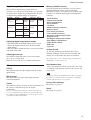
New VISCA Commands
The following two commands have been added.
• Register Set command
Changing the value of the register of the camera
control CPU directly enables use of a large number of
modes.
Note
After changing the command, be sure to turn the camera off once,
and then turn on again. Otherwise the new command will not
become effective and the mode will not be changed.
Function
Syntax
Register set 8x 01 04 24 mm 0p 0p ff
Back Light Compensation
VISCA bit rate
Frame rate
Digital I/F format
selection register
Register # Value
mm
pp
Aperture Control
Aperture control is a function which adjusts the
enhancement of the edges of objects in the picture.
There are 16 levels of adjustment, starting from “no
enhancement.” When shooting text, this control may
help by making the text sharper.
Note
VISCA Baud Rate
00
Frame Rate
70
IF Mode
71
00
9600 bps
01
19200 bps
02
38400 bps
01
29.97 fps
02
25 fps
01
Progressive
02
Interlace (REC656 Only)
When the background of the subject is too bright, or
when the subject is too dark due to shooting in the AE
mode, back light compensation will make the subject
appear clearer.
Slow Shutter – Auto/Manual
When the Slow Shutter is set to “Auto,” this ensures
that the slow shutter is engaged automatically when the
brightness drops. This occurs only when the AE mode
is set to “Full Auto.”
“Slow Shutter Manual” is the factory setting.
Camera ID
The ID can be set up to 65,536 (0000 to FFFF). As this
will be memorized in the nonvolatile memory inside
the camera, data will be saved regardless of whether it
has been backed up.
10
Basic Functions
Digital Image Output Modes
Three kinds of digital image output modes are
available. Also, 30 fps and 25 fps modes are available
for each of these digital image output modes. In total,
six digital image output modes are supported.
I/F mode
Output
SYNC
Frame rate Clock
16bit
Progressive
YUV
HSYNC/
VSYNC
29.97 fps /
25.0 fps
13.5 MHz
YUV
HSYNC/
VSYNC
29.97 fps /
25.0 fps
27.0 MHz
8-bit 4:2:2
SAV/EAV
29.97 fps /
25.0 fps
27.0 MHz
16-bit 4:2:2
8bit
Progressive
8bit Interlace YUV
Scan
8-bit 4:2:2
HSYNC/
VSYNC
SAV/EAV
Mode set at the factory : 16-bit PS, 29.97 fps
Selecting digital image output modes
• The S501 switch of the FCB camera allows you to
change the output mode between 16-bit and 8-bit
output modes.
• The new VISCA command allows you to select either
PS mode or IS mode.
Selecting frame rate
New VISCA commands allow you to select either
29.97 (p) or 25.0 (p) mode.
Either 59.94 (i) or 50.0 (i) is available for Interlace.
Others
E-FLIP
This function turns the video output from the camera
upside down.
Mirror Image
This function reverses the video output from the
camera horizontally.
Freeze
This function captures an image in the field memory of
the camera so that this image can be output
continuously.
Because communication inside the camera is based on V
cycle, the captured image is always the one 3V to 4Vs after
the sending of a Command. Thus, you can not specify a time
period after sending a Command.
Memory (Position Preset)
Using the position preset function, 6 sets of camera
shooting conditions can be stored and recalled.
This function allows you to achieve the desired status
instantly even without adjusting the following items
each time:
• Zoom Position
• Digital Zoom On/Off
• Focus Auto/Manual
• Focus Position
• AE Mode
• Shutter control parameters
• Bright Control
• Iris control parameters
• Gain control parameters
• Exposure Compensation On/Off
• Exposure Level
• Backlight Compensation On/Off
• Slow Shutter Auto/Manual
• White Balance Mode
• R/B Gain
• Aperture
Custom Preset
As with the position preset function, the camera
shooting conditions can be stored and recalled. The
settings are recalled when the power is turned on.
For setting items, see the “Initial Settings, Custom Preset
and Backup” section on page 28.
User Memory Area
A user area of 16 bytes allows you to write data, such
as an ID for each customer, data for each system, and
so on, freely.
Note
Rewriting of memory is not unlimited. Be careful to avoid using
the memory area for such as unnecessary tasks as rewriting the
contents of the memory for every operation.
Privacy Zone Settings
For details, see page 13.
Alarm
For details, see page 17.
11
Basic Functions
Title Display
The camera can be given a title containing up to 20
characters such as “ENTRANCE” or “LOBBY”. The
position of the first character (horizontal, vertical) of
the title, blinking state, and color can also be changed.
Vposition
00 to 0A
Hposition
00 to 17
00: Does not blink
Blink
01: Blinks
Color
00
White
01
Yellow
02
Violet
03
Red
04
Cyan
05
Green
06
Blue
00
01
02
03
04
05
06
07
A
B
C
D
E
F
G
H
08
09
0a
0b
0c
0d
0e
0f
I
J
K
L
M
N
O
P
10
11
12
13
14
15
16
17
Q
R
S
T
U
V
W
X
18
19
1a
1b
1c
1d
1e
1f
Y
Z
&
?
!
1
2
20
21
22
23
24
25
26
27
3
4
5
6
7
8
9
0
28
29
2a
2b
2c
2d
2e
2f
À
È
Ì
Ò
Ù
Á
É
Í
30
31
32
33
34
35
36
37
Ó
Ú
Â
Ê
Ô
Æ
Œ
Ã
38
39
3a
3b
3c
3d
3e
3f
Õ
Ñ
Ç
ß
Ä
Ï
Ö
Ü
40
41
42
43
44
45
46
47
Å
$
F
¥
DM
£
¿
¡
48
49
4a
4b
4c
4d
4e
4f
ø
“
:
‘
.
,
/
-
12
Basic Functions
Privacy Zone Function
Features
Privacy Zone masking protects private objects and
areas such as house windows, entrances, and exits
which are within the camera’s range of vision but not
subject to surveillance.
Privacy zone masking can be masked on the monitor to
protect privacy.
• Mask can be set on up to 24 places according to Pan/
Tilt positions.
• Mask can be displayed on 8 places per screen
simultaneously.
• Privacy Zones are displayed according to priority in
alphabetical order.
• Individual on/off zone masking settings.
• Two colors from among 28 colors including a mosaic
can be individually set for each of 24 privacy zones.
(Color mosaic masking is available for privacy zone.)
• Interlocking control with zooming.
• Interlocking control with Pan/Tilt.
• Non-interlocking control with Pan/Tilt.
Timing chart
8x 01 .. .. FF
(Mask Setting Command)
1V
Setting command is reflected
at this timing.
13
Basic Functions
Privacy Zone Setting Command List
Command Set
Command
Command Packet
Comments
CAM_PrivacyZone
SetMask
8x 01 04 76 mm nn
0r 0r 0s 0s FF
Setting Mask(Size)
See “mm: mask setting list”, “nn: setting”, and
“rr: w, ss: h” in “Parameters” on page 15.
Display
8x 01 04 77 pp pp pp pp FF
Setting Mask Display On/Off
See “pp pp pp pp: Mask bit” in “Parameters”
on page 15.
pp pp pp pp: Mask setting (0: OFF, 1: ON)
SetMaskColor
8x 01 04 78 pp pp pp pp qq rr FF
Setting Color of Mask
See “pp pp pp pp: Mask bit” and “qq, rr: Color
code” in “Parameters” on page 15.
qq: Color setting when setting the Mask bit
to 0
rr: Color setting when setting the Mask bit
to 1
SetPanTiltAngle
8x 01 04 79 0p 0p 0p 0q 0q 0q FF
Setting Pan/Tilt Angle
See “Setting pan/tilt angle” in “Parameters” on
page 15.
ppp: Pan angle, qqq: Tilt angle
SetPTZMask
8x 01 04 7B mm 0p 0p 0p
0q 0q 0q 0r 0r 0r 0r FF
Setting the direct position of PTZ
mm: See “mm: mask setting list” and “Setting
pan/tilt angle” in “Parameters” on page 15.
ppp: Pan , qqq: Tilt , rrrr: Zoom
Non_InterlockMask 8x 01 04 6F mm
0p 0p 0q 0q 0r 0r 0s 0s FF
Setting non-interlocking the mask to pan/tilt
See “mm: mask setting list” and “pp: x, qq: y,
rr: w, ss: h” in “Parameters” on page 15.
Grid On
8x 01 04 7C 02 FF
Setting Grid Display On/Off
Grid Off
8x 01 04 7C 03 FF
CenterLineOn
8x 01 04 7C 04 FF
Setting the center line On
Privacy Zone Inquiry Command List
Inquiry Command Command Packet
Inquiry Packet
Comments
CAM_Privacy
DisplayInq
8x 09 04 77 FF
y0 50 pp pp pp pp FF
Inquiry about the status of Setting Mask
Display On/Off
See “pp pp pp pp: Mask bit” in “Parameters”
on page 15.
1:On, 0:Off
CAM_PrivacyPan
TiltInq
8x 09 04 79 FF
y0 50 0p 0p 0p 0q 0q 0q FF
Inquiry about the pan/tilt position currently set
See “Setting pan/tilt angle” in “Parameters” on
page 15.
ppp: Pan, qqq: Tilt
CAM_Privacy
PTZInq
8x 09 04 7B mm FF y0 50 0p 0p 0p 0q 0q 0q 0r 0r
0r 0r FF
CAM_Privacy
MonitorInq
8x 09 04 6F FF
y0 50 pp pp pp pp FF
Inquiry about pan/tilt/zoom position at the mm
Mask setting
See “mm: Mask setting list” and “Setting pan/
tilt angle” in “Parameters” on page 15.
ppp: Pan Position,
qqq: Tilt Position
rrrr: Zoom Position
Inquiry about the mask currently displayed
See “pp pp pp pp: Mask bit” in “Parameters”
on page 15.
14
Basic Functions
Parameters
mm: Mask setting list
nn: Setting
Mask Name
mm (Hex)
Mask Name
Mask_A
00h
Mask_B
01h
Mask_C
mm (Hex)
nn
Setting
Mask_M
0Ch
00
Mask_N
0Dh
Resetting the zone size (the value of w, h)
for the existing mask.
02h
Mask_O
0Eh
01
Mask_D
03h
Mask_P
0Fh
Setting newly the zone size (the value of
w, h).
Mask_E
04h
Mask_Q
10h
Mask_F
05h
Mask_R
11h
Mask_G
06h
Mask_S
12h
Mask_H
07h
Mask_T
13h
Mask_I
08h
Mask_U
14h
Mask_J
09h
Mask_V
15h
Mask_K
0Ah
Mask_W
16h
Mask_L
0Bh
Mask_X
17h
pp: x, qq: y, rr: w, ss: h
160
3Ch
mask
h w
0 (x,y)
120
Note
B0h
50h
The priority order of the mask display is in the sequence from A
(highest) to X (lowest).
When you set the parameters of masks non-sequentially, it is
recommended that you set the mask whose priority order is higher,
first.
C4h
Effective display area
pp pp pp pp: Mask bit
pp
pp
pp
pp
bit
7 6 5 4 3 2 1 0 7 6 5 4 3 2 1 0 7 6 5 4 3 2 1 0 7 6 5 4 3 2 1 0
Mask
- - X W V U T S - - R Q P O N M - - L K J I H G - - F E D C B A
Setting pan/tilt angle
qq, rr: Color code
Mask (Color)
Code (qq, rr)
Semi-transparency (qq, rr)
Black
00h
10h
Gray1
01h
11h
Gray2
02h
12h
-180
-90
Gray3
03h
13h
800h
C00h
Gray4
04h
14h
Gray5
05h
15h
Gray6
06h
16h
White
07h
17h
Red
08h
18h
Green
09h
19h
Blue
0Ah
1Ah
Cyan
0Bh
1Bh
Yellow
0Ch
1Ch
Magenta
0Dh
1Dh
Mosaic
7Fh
–
Angle/Parameter of Angle (ppp, qqq)
0
90
180
400h
800h
Set the angle resolution to 360 (degree)/4096 (1000h).
15
Basic Functions
Details of Setting Commands
Set Mask
Command: 8x 01 04 76 mm nn 0r 0r 0s 0s FF
Parameters:
mm
Setting Mask
See “mm: mask setting list” in “Parameters” on page 15.
nn
Selects new setting or resetting for the zone. See nn:
Setting” in “Parameters” on page 15.
rr
Sets the half value “w” of the Mask Width.
ss
Sets the half value “h” of the Mask Height.
See “rr: w, ss: h” in “Parameters” on page 15.
Comments: To set the mask, first display the object
at the center of the screen. When “nn” is set to 1,
the current Pan/Tilt/Zoom position is recorded in
internal memory.
When “nn” is set to 0, the Pan/Tilt/Zoom position
in memory is not changed.
Notes
• The tilt angle at which you can set the mask is between –70 to
+70 degrees.
• It is recommended that you set the size to at least twice the size
of the object (height and width).
Set Display
Command: 8x 01 04 77 pp pp pp pp FF
Parameter:
pp pp pp pp Each 24 Privacy Zones corresponds to 1 bit.
See “pp pp pp pp: Mask bit” in “Parameters” on
page 15.
Comments: Each of 24 Privacy zones can be
switched on and off individually by a single
VISCA command. If you want to display a
Privacy zone, you must set its bit to 1. If you do
not want to display a Privacy zone, you must set
its bit to 0.
Set Mask Color
Command: 8x 01 04 78 pp pp pp pp qq rr FF
Parameter:
pp pp pp pp Each 24 Privacy Zones correspond with the BIT.
See “pp pp pp pp: Mask bit” in “Parameters” on
page 15.
qq
Set the color code include the semi-transparency
code.
rr
Set the color code include the semi-transparency
code. See “qq, rr: Color code” in “Parameters” on
page 15.
Comments: Two different color masks can be
chosen.
The colors can be chosen from among 14 colors
including the possibility for semi-transparency of
each color. Therefore two colors from among the
total of 28 colors can be individually set for each
of 24 privacy zones.
If the bit of parameter (pp pp pp pp) is set to “0”,
mask color will be “qq” color (Color code). If the
bit of parameter (pp pp pp pp) is set to “1”, the
mask color will be “rr” color (Color code).
Example: 8x 01 04 78 00 00 00 03 10 07 FF
The mask color of Mask_A and Mask_B is White
(color code 07h), and the mask color of the other
Mask (C to X) is semi-transparent Black (color
code 10h).
Set Pan Tilt Angle
Command: 8x 01 04 79 0p 0p 0p 0q 0q 0q FF
Parameter:
ppp
Pan Angle
qqq
Tilt Angle
See “Setting pan/tilt angle” in “Parameters” on page
15.
Comments: Pan/Tilt angle settings are hexadecimal
data.
The resolution of Pan/Tilt angle is 0.088 degrees.
Note
When you set the pan/tilt angle, locate the pan/tilt position at the
center point of the FCB camera’s position.
Non Interlock Mask
Command: 8x 01 04 6F mm 0p 0p 0q 0q 0r 0r 0s 0s
FF
Parameters:
mm
Setting Mask
See “mm: mask setting list” in “Parameters” on page 15.
pp
Sets the center position “x” of the Mask on screen.
qq
Sets the center position “y” of the Mask on screen.
rr
Sets the half value “w” of the Mask Width.
ss
Sets the half value “h” of the Mask Height.
See “pp: x, qq: y, rr: w, ss: h” in “Parameters” on page 15.
Commands: Mask does not interlock with pan/tilt.
The limitations of parameters are as follows.
(hexadecimal representation)
x: ±50h
w: ±50h
y: ±3ch
h: ±3ch
Note
When the Set Mask command and the Non Interlock Mask
command are set to the same mask, the command set later
becomes effective.
16
Basic Functions
Grid
Alarm Function
Use the grid displayed on the screen to set mask
positions (see the figure below).
This function instructs the camera to detect movement
within the monitoring area and then send an alarm
signal automatically.
A High level signal is output when camera detects
movement inside the monitoring area. A Low level
signal is output when object stops moving.
However, when the mode is set to “DAY/NIGHT”, the
High level signal is output for dark and the Low level
signal is output for bright.
The Detect signal goes out through the serial command
(VISCA) communication line.
14hex (20(10))
14hex (20(10))
Example
1. A door is motionless, so the Detect Level is Low.
2. At the moment when the door is opened by
someone, the Detect Level goes to High.
3. The Detect Level is High while the shooting object
is moving.
4. When the door is closed, Detect Level goes to Low
again, or signals are output only once at the time of
switching between High Level and Low Level.
17
Basic Functions
ALARM Setting Command List
Command Set
Command
Command Packet
Comments
CAM _ Alarm
On
8x 01 04 6B 02 FF
Alarm start
Off
8x 01 04 6B 03 FF
Alarm stop
Set Mode
8x 01 04 6C pp FF
Mode Setting
*Select one from 13 modes
Set Day Night Level
8x 01 04 6D 0p 0p 0p
0q 0q 0q FF
ppp: Day distinction AE level
qqq: Night distinction AE level.
90 07 04 6B 01 FF
High signal output
(Low t High edge)
90 07 04 6B 00 FF
Low signal output
(High t Low edge)
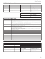
VISCA Mode Code (pp) Details of Mode
00
Set the internal focus position. When focus movement is detected, the detect signal is High. When focus goes
back to the previous position, the detect signal is Low.
01
Set a fixed period of time. When focus does not move during the time, the focus position is memorized as a
rest position and the detect signal is Low.
When focus moves, the detect signal is High. Afterwards when focus does not move for the fixed period of
time, the focus position is memorized and the detect signal becomes Low.
02
Set the internal AE Level. When AE movement is detected, the detect signal is High. When AE Level goes
back to the previous level, the detect signal is Low.
03
Set a fixed period of time. When AE Level does not change during this time, the AE value is memorized as a
rest value and the detect signal is Low.
When AE value changes, the detect signal is High.
Afterwards when AE value does not change for the fixed period of time, the AE value is memorized and the
detect signal becomes Low.
04
mode “00” and mode “02”
05
mode “00” and mode “03”
06
mode “01” and mode “02”
07
mode “01” and mode “03”
08
mode “00” or mode “02”
09
mode “00” or mode “03”
0A
mode “01” or mode “02”
0B
mode “01” or mode “03”
0C
Day-Night Mode
ALARM Inquiry Command List
Inquiry Command
Command Packet
Inquiry Packet
Comments
CAM _ Alarm Inq
8x 09 04 6B FF
y0 50 02 FF
On
y0 50 03 FF
Off
CAM _ Alarm Mode Inq
8x 09 04 6C FF
y0 50 pp FF
pp: Alarm Mode
CAM_AlarmDayNightLevel Inq
8x 09 04 6D FF
y0 50 0p 0p 0p
0q 0q 0q 0r 0r 0r FF
ppp: Day setting AE Level
qqq; Night setting AE Level
rrr: Now AE Level
CAM_AlarmDetLevelInq
8x 09 04 6E FF
y0 50 01 FF
y0 50 00 FF
Detect Level is High.
Detect Level is Low.
18
Basic Functions
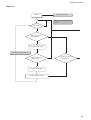
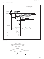
Flowchart of 12 Modes Function
Mode “00”
Set the Focus Position
Hysteresis.
Set to the factory preset
Alarm On
Focus Position into memory
AE moves
Focus moves outside of
the hysteresis.
*
High level signal output
* Repeat this loop until Alarm off.
Focus goes back to the
previous position.
Low level signal output
Far
Hysteresis
Focus
Position
Near
High
Low
19
Basic Functions
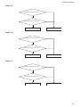
Mode “01”
Alarm On
Focus Position into memory
Hysteresis is set to the factory
preset.
AE moves.
Focus moves outside of the
hysteresis.
*
High level signal output
* Repeat this loop until Alarm off.
AE does not move for
a period of time.
AE does not move for
a period of time.
Low level signal output
Update the Focus position data.
20
Basic Functions
Mode “02”
Set the AE level Hysteresis.
Set to the factory preset
Alarm On
AE Level into memory
AE moves
AE moves outside of
the hysteresis.
*
High level signal output
* Repeat this loop until Alarm off.
AE goes back to the
previous level.
Low level signal output
Bright
Hysteresis
AE Level
Dark
High
Low
21
Basic Functions
Mode “03”
Alarm On
AE level into memory
Hysteresis is set to the factory
preset.
AE moves.
AE moves outside of
the hysteresis.
High level signal output
*
* Repeat this loop until Alarm off.
AE does not move for
a period of time.
AE does not move for
a period of time.
Low level signal output
Update the AE level data
22
Basic Functions
Details of Mode “01”/”03"
T1: Reset interval timer (5sec)
T2: Detect timer (2sec)
T3: High level signal count timer (2sec)
Alarm ON
Hysteresis
Reset
Focus Pos
AE Level
Reset
Reset
Reset
T1
T1
T1
T2
T3
High
Signal level
Low
Low
T1:
T2:
T3:
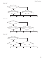
Mode “04”
High output result of mode “00”
High output result of mode “02”
High output
Low output
23
Basic Functions
Mode “05”
High output result of mode “00”
High output result of mode “03”
High output
Low output
Mode “06”
High output result of mode “01”
High output result of mode “02”
High output
Low output
Mode “07”
High output result of mode “01”
High output result of mode “03”
High output
Low output
24
Basic Functions
Mode “08”
High output result of mode “00”
High output result of mode “02”
High output
High output result of mode “02”
High output
High output
Low output
Mode “09”
High output result of mode “00”
High output result of mode “03”
High output
High output result of mode “03”
High output
High output
Low output
Mode “0A”
High output result of mode “01”
High output result of mode “02”
High output
High output result of mode “02”
High output
High output
Low output
25
Basic Functions
Mode “0B”
High output result of mode “01”
High output result of mode “03”
High output
High output result of mode “03”
High output
High output
Low output
Day-Night Mode (Mode “0C”)
Set the Day-Night Mode and the Day/
Night AE level.
Setting by the VISCA Cmd.
Starting distinction between Day
and Night.
Alarm On
AE move
Yes
Brightness is higher than
Day AE level.
Yes
No
No
Brightness is higher than Night
AE level.
Yes
Low level signal output
Low level signal output
High level signal output
Bright
Day
AE level
Hysteresis
Night
AE level
t
t
Dark
Setting the period time
“t” to the factory preset
High
Signal level
Low
Low
26
Basic Functions
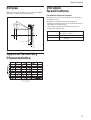
Eclipse
21.82˚
30.97˚
When designing the housing, refer to the dimensional
allowance as shown in the figure below.
Vibration
Specifications
Test Method (Random vibration)
• Fix the camera at the four fixation points of the base
using M2 screws.
• Perform the random vibration test under the
following conditions in the X, Y and Z directions for
20 minutes in each direction.
• The camera vibration specification is to have no
malfunction after this test.
9.56
8.92
4.14 m2/s3
Power spectrum density 5 to 50 Hz
50 to 100 Hz –36 dB/oct
Effective overall value
14.3 m/s2
Test time
20 minutes
{0.043 G2/Hz}
{1.46 G}
Spectral Sensitivity
Characteristics
27
Basic Functions
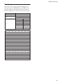
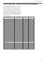
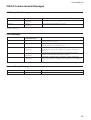
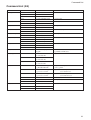
Initial Settings, Custom Preset and Backup
Initial settings for the various functions are indicated
in the “Initial settings” column.
The “Custom preset” column indicates whether the
custom preset function can be used to store the
settings. The function enables the stored settings to be
recalled automatically when the camera is turned on.
The “Standby backup” column indicates whether the
data is preserved even when the camera is powered
OFF. A circle “a” in this column signifies that the
data is preserved. A cross “×” signifies that the data
IS NOT preserved.
Initial settings
Custom
preset
Standby
backup
Zoom Position
Wide end
a
a
Focus Position
—
a
a
Focus Auto/Manual
Auto
a
a
Near Limit Setting
C000h (10 mm)
a
a
AF Sensitivity
Normal
a
a
AF Mode
Normal
a
a
AF Run Time
5 sec
a
a
AF Interval
5 sec
a
a
WB Mode
Auto
a
a
WB Data (Rgain, Bgain)
—
a
a
One Push WB Data
—
a
a
Full Auto
a
a
Manual
a
a
1
/30 s (30fps), /25 s (25fps)
a
a
Iris Position
—
a
a
Gain Position
—
a
a
Bright Position
—
a
a
Exposure Compensation On/Off
Off
a
a
Exposure Compensation Amount
±0
a
a
Backlight On/Off
Off
a
a
Mode/Position
AE Mode
Slow Shutter Mode
Shutter Position
1
Off
a
a
X=8, Y=8
a
a
5
a
a
LR Reverse On/Off
Off
a
a
Freeze On/Off
Off
×
×
Spot AE On/Off
Spot AE Position Setting
Aperture Level
Off
a
a
Same as the initial value setting
a
a
Display On/Off
Off
a
a
Mute On/Off
Off
×
×
Picture Effect
Camera Memory
28
Basic Functions
Custom
Standby
preset
backup
Off
a
a
Title Setting
—
a
a
Mask Setting
—
a
a
Mask Display On/Off
Off
a
a
Mask Color Setting
—
a
a
Alarm On/Off
Off
a
a
Alarm Mode
—
a
a
Alarm Detect Level
—
a
a
E-Flip On/Off
Off
a
a
Privacy Zone On/Off
Off
a
a
Privacy Zone Setting
—
a
a
Off
a
a
0000h
a
a
Mode/Position
Title Display On/Off
Key Lock On/Off
Camera ID
Initial settings
Note
The number of times data can be written to EEPROM (by
executing Custom Preset) is limited.
29
Mode
×
×
Lens Initialization
a) × during recalling from key
×
×
×
×
Camera Memory Set/Reset
Camera Memory Recall
×
×
×
×
×
×
×
Focus Near Limit
AF Sensitivity Normal/Low
×
×
×
×
×
One Push AF
Focus Infinity
AF Mode Norm/Interval/Zoom
×
×
Focus Auto/Manual
AF Activation Time/Interval Setting
×
×
×
×
Focus Far/Near/Stop
Focus Direct
×
×
×
×
×
Zoom Direct
Initializing
×
Zoom Focus Direct
Zoom Tele/Wide/Stop
Power Off
a
a
Power On/Off
Lens
a
a
a
a
a
a
IF_Clear
Initializing
Power Off
Command Cancel
Address Set
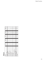
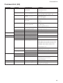
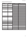
Mode
Condition
Mode Condition
a
a
a
a
a
a
×
×
a
a
×
×
a
a
×
×
a
×
a
a
×
×
a
a
×
×
a
×
a
Freeze On
a
a
a
a
a
Freeze On
Power On
a
a
a
a
Power On
×
×
×
×
×
a
a
a
a
a
a
a
a
a
×
a
×
×
×
×
a
a
a
×
×
×
×
a
×
×
a
a
×
×
×
a
a
a
×
×
×
×
×
×
a
×
×
Zoom Direct Focus Direct ZmFo Direct
a a)
×
×
×
×
×
×
×
×
×
×
×
×
MemRecall
a
a
a
a
MemRecall
a
a
a
a
a
a
a
a
×
a
×
×
×
a
a
Focus Auto
Basic Functions
30
×
×
×
×
×
×
×
×
Exposure Compensation Setting
Backlight On/Off
SpotAE On/Off
SpotAE Setting
×
×
×
×
×
×
×
Gain Setting
Bright Setting
×
×
×
×
×
Shutter Setting
Iris Setting
Slow Shutter Auto/Manual
×
×
Bright
Exposure Compensation On/Off
×
×
×
×
Shutter Priority
Iris Priority
×
×
×
×
AE Full Auto
Initializing
AE Manual
Mode
Power Off
×
×
BGain Setting
Exposure
×
×
×
×
One Push WB
×
×
RGain Setting
Initializing
Power Off
WB Mode Switchover
Mode
White Balance
×
×
×
×
a
a
a
a
×
×
a
a
×
×
a
a
×
×
a
×
a
a
×
×
a
a
×
×
a
a
Freeze On
×
a
Power On
×
×
a
×
a
a
Freeze On
Power On
×
×
×
×
×
×
×
×
×
×
×
×
×
×
×
MemRecall
×
×
×
×
MemRecall
a
a
a
a
a
a
×
×
×
×
a
a
a
a
a
AE Full Auto
×
×
×
a
WB AUTO
a
a
×
a
a
a
×
a
a
a
×
a
a
a
a
AE Manual
×
×
×
a
Indoor
a
a
×
a
a
a
×
×
×
a
a
a
a
a
a
ShutterPriority
×
×
×
a
Outdoor
a
a
×
a
a
a
×
×
a
×
×
a
a
a
a
Iris Priority
×
×
a
a
OnePush
a
a
×
a
a
a
a
×
×
×
a
a
a
a
a
Bright
×
×
×
a
ATW
a
a
×
a
Manual
Basic Functions
31
×
×
×
×
×
×
Privacy Zone Setting
ID Write
×
×
Privacy Zone On/Off/Clear
Key Lock On/Off
×
×
×
×
Mute On/Off
Title Setting
×
×
×
×
Picture Effect Setting
Display On/Off
×
×
×
×
LR_Reverse On/Off
×
×
Aperture Setting
Freeze On/Off
Initializing
Power Off
Mode
Others
a
a
a
a
a
a
a
a
a
a
a
a
×
a
a
a
×
a
a
×
a
a
Freeze On
Power On
a
a
a
a
a
a
a
×
×
×
×
MemRecall
Basic Functions
32
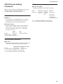
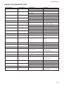
Command List
Command List
VISCA1)/RS-232C
Commands
This Manual outlines an RS-232C control protocol and
command list for certain Sony cameras from which
control software can be developed.
THIS CONTROL PROTOCOL AND COMMAND
LIST IS PROVIDED BY SONY ON AN “AS-IS
BASIS” WITHOUT WARRANTY OF ANY KIND.
SONY DOES NOT WARRANT ANY PARTICULAR
RESULT FROM THE USE OF THIS CONTROL
PROTOCOL AND COMMAND LIST AND
DISCLAIMS AND EXCLUDES ALL
WARRANTIES, EXPRESS OR IMPLIED, WITH
RESPECT TO THAT CONTROL PROTOCOL AND
COMMAND LIST, INCLUDING, BUT NOT
LIMITED TO, ANY OR ALL IMPLIED
WARRANTIES OF MERCHANTABILITY OR
FITNESS FOR A PARTICULAR PURPOSE. IN
FACT, SONY SPECIFICALLY ACKNOWLEDGES
THAT SOFTWARE DEVELOPED BASED ON THIS
CONTROL PROTOCOL AND COMMAND LIST
MAY CAUSE MALFUNCTION OR DAMAGE TO
HARDWARE AND SOFTWARE USED WITH IT
(INCLUDING SONY HARDWARE AND
SOFTWARE) AND SPECIFICALLY DISCLAIMS
ANY LIABILITY FOR ANY SUCH
MALFUNCTION OR DAMAGE. THIS CONTROL
PROTOCOL AND COMMAND LIST SHOULD BE
USED WITH CAUTION.
Overview of VISCA
In VISCA the device outputting commands, for
example, a computer, is called the controller. The
device receiving the commands, an FCB camera is
called the peripheral device. In VISCA, up to seven
peripheral devices like the FCB camera can be
connected to one controller using communication
conforming to the RS-232C standard. The parameters
of RS-232C are as follows:
• Communication speed: 9.6 kbps/19.2 kbps/
38.4 kbps
• Data bits : 8
• Start bit : 1
• Stop bit : 1/2
• Non parity
Flow control using XON/XOFF, RTS/CTS, etc., is not
supported.
................................................................................................................................................................................................................................
1) VISCA is a protocol which controls consumer camcorders developed by Sony. “VISCA” is a trademark of Sony Corporation.
33
Command List
VISCA Communication
Specifications
assigned address 2 is 82H. In the command list, as the
header is 8X, input the address of the camera at X. The
header of the reply packet from the camera assigned
address 1 is 90H. The packet from the camera assigned
address 2 is A0H.
Some of the commands for setting cameras can be sent
to all devices at one time (broadcast). In the case of
broadcast, the header should be hexadecimal 88H.
When the terminator is FFH, it signifies the end of the
packet.
VISCA Packet Structure
The basic unit of VISCA communication is called a
packet. The first byte of the packet is called the header
and comprises the sender’s and receiver’s addresses.
For example, the header of the packet sent to the FCB
camera assigned address 1 from the controller (address
0) is hexadecimal 81H. The packet sent to the camera
Packet (3 to 16 bytes)
Header
Message (1 to 14 bytes)
Byte 1
1
Sender’s
address
0
Byte 2
Terminator
FF
Byte 3
Receiver’s address
Bit 7 Bit 6 Bit 5 Bit 4 Bit 3 Bit 2 Bit 1 Bit 0
(MSB)
(LSB)
1
1
1
1
1
1
1
1
Bit 7 Bit 6 Bit 5 Bit 4 Bit 3 Bit 2 Bit 1 Bit 0
(MSB)
(LSB)
Command and Inquiry
● Command
Sends operational commands to the FCB camera.
● Inquiry
Used for inquiring about the current state of the
FCB camera.
Note
QQ1) = Command/Inquiry,
RR2) = category code
QQ = 01 (Command), 09 (Inquiry)
RR = 00 (Interface), 04 (camera 1), 06 (Pan/Tilter), 07 (camera 2)
Inquiry
1)
2)
Command Packet
8X QQ RR ... FF
X = 1 to 7: FCB camera address
34
Command List
Responses for Commands and Inquiries
Command Execution Cancel
● ACK message
Returned by the FCB camera when it receives a
command. No ACK message is returned for
inquiries.
To cancel a command which has already been sent,
send the Cancel command as the next command. To
cancel one of any two commands which have been
sent, use the cancel message.
● Completion message
Returned by the FCB camera when execution of
commands or inquiries is completed. In the case of
inquiry commands, it will contain reply data for the
inquiry after the 3rd byte of the packet. If the ACK
message is omitted, the socket number will contain
0.
Cancel Packet
Note
Cancel
8X 2Y FF
Y = socket number
X = 1 to 7: FCB camera address, Y = socket number
Reply Packet
Ack
X0 4Y FF
Completion (commands) X0 5Y FF
Completion (Inquiries)
X0 5Y ... FF
X = 9 to F: FCB camera address + 8
An error message will be returned for this command,
but this is not a mistake. This message indicates that
the command has been canceled.
Note
Y = socket number
Y = socket number
Y = socket number
● Error message
When a command or inquiry command could not be
executed or failed, an error message is returned
instead of the completion message.
Error Packet
Description
X0 6Y 01 FF
Message length error (>14 bytes)
X0 6Y 02 FF
Syntax Error
X0 6Y 03 FF
Command buffer full
X0 6Y 04 FF
Command cancelled
X0 6Y 05 FF
No socket (to be cancelled)
X0 6Y 41 FF
Command not executable
X = 9 to F: FCB camera address + 8, Y = socket number
Socket Number
When command messages are sent to the FCB camera,
it is normal to send the next command message after
waiting for the completion message or error message
to return. However to deal with advanced uses, the
camera has two buffers (memories) for commands, so
that up to two commands including the commands
currently being executed can be received. When the
camera receives commands, it notifies the sender
which command buffer was used using the socket
number of the ACK message. As the completion
message or error message also has a socket number, it
indicates which command has ended. Even when two
command buffers are being used at any one time, a
camera management command and some inquiry
messages can be executed.
The ACK message is not returned for these commands
and inquiries, and only the completion message of
socket number 0 is returned.
35
Command List
VISCA Device Setting
Command
Before starting control of the FCB camera, be sure to
send the Address command and the IF_Clear
command using the broadcast function.
For VISCA Network Administration
● Address
Sets an address of a peripheral device. Use when
initializing the network and when receiving the
network change message indicated below.
VISCA Interface and Inquiry
● CAM_VersionInq
Returns information on the VISCA interface.
Inquiry
CAM_VersionInq
Inquiry Packet
8X 09 00 02 FF
HH HH JJ JJ
Reply Packet
Y0 50 GG GG
(0020: Sony)
KK FF
Description
GGGG = Vender ID
HHHH = Model ID
0441 = FCB-PV10
JJJJ = ROM revision
KK = Maximum socket # (02)
X = 1 to 7: FCB camera address (For inquiry packet)
X = 9 to F: FCB camera address +8 (For reply packet)
● Network Change
Sent from the peripheral device to the controller
when a device is removed from or added to the
network. The address must be re-set when this
message is received.
Packet
Address
88 30 01 FF
Network Change
X0 38 FF
X = 9 to F: FCB camera address + 8
Note
Always broadcasted.
VISCA Interface Command
● IF_Clear
Clears the command buffers in the FCB camera and
cancels the command currently being executed.
Command Packet Reply Packet Note
IF_Clear
8X 01 00 01FF
X0 50 FF
IF_Clear (broadcast) 88 01 00 01 FF
88 01 00 01 FF
X = 1 to 7: FCB camera address (For inquiry packet)
X = 9 to F: FCB camera address +8 (For reply packet)
36
Command List
VISCA Command/ACK Protocol
Command
Command Message
Reply Message
Comments
General Command
81 01 04 38 02 FF
(Example)
90 41 FF (ACK)+90 51 FF
(Completion)
90 42 FF
90 52 FF
Returns ACK when a command has been accepted, and
Completion when a command has been executed.
81 01 04 38 FF
(Example)
90 60 02 FF (Syntax Error)
Accepted a command which is not supported or a command
lacking parameters.
81 01 04 38 02 FF
(Example)
90 60 03 FF
(Command Buffer Full)
There are two commands currently being executed, and the
command could not be accepted.
81 01 04 08 02 FF
(Example)
90 61 41 FF
(Command Not Executable)
90 62 41FF
Could not execute the command in the current mode.
81 09 04 38 FF
(Example)
90 50 02 FF (Completion)
ACK is not returned for the inquiry command.
81 09 05 38 FF
(Example)
90 60 02 FF (Syntax Error)
Accepted an incompatible command.
Inquiry Command
Address Set
88 30 01 FF
88 30 02 FF
Returned the device address to +1.
IF_Clear (Broadcast)
88 01 00 01 FF
88 01 00 01 FF
Returned the same command.
IF_Clear (For x)
8x 01 00 01 FF
z0 50 FF (Completion)
ACK is not returned for this command.
Command Cancel
8x 2y FF
z0 6y 04 FF
(Command Canceled)
Returned when the command of the socket specified is canceled.
Completion for the command canceled is not returned.
z0 6y 05 FF (No Socket)
Returned when the command of the specified socket has already
been completed or when the socket number specified is wrong.
37
Command List
VISCA Camera-Issued Messages
ACK/Completion Messages
Command Messages
Comments
ACK
z0 4y FF
(y:Socket No.)
Returned when the command is accepted.
Completion
z0 5y FF
(y:Socket No.)
Returned when the command has been executed.
z = Device address + 8
Error Messages
Command Messages
Comments
Syntax Error
z0 60 02 FF
Returned when the command format is different or when a command with illegal
command parameters is accepted.
Command Buffer Full
z0 60 03 FF
Indicates that two sockets are already being used (executing two commands) and the
command could not be accepted when received.
Command Canceled
z0 6y 04 FF
(y:Socket No.)
Returned when a command which is being executed in a socket specified by the
cancel command is canceled. The completion message for the command is not
returned.
No Socket
z0 6y 05 FF
(y:Socket No.)
Returned when no command is executed in a socket specified by the cancel
command, or when an invalid socket number is specified.
Command Not Executable
z0 6y 41 FF
(y:Socket No.)
Returned when a command cannot be executed due to current conditions. For
example, when commands controlling the focus manually are received during auto
focus.
Network Change Message
Network Change
Command Message
Comments
z0 38 FF
Issued when power is being routed.
38
Command List
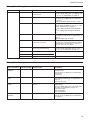
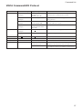
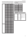
FCB Camera Commands
Command List (1/4)
Command Set
Command
Command Packet
AddressSet
Broadcast
88 30 01 FF
IF_Clear
Broadcast
88 01 00 01 FF
CommandCancel
CAM_Power
CAM_Zoom
CAM_Focus
AF Sensitivity
CAM_AFMode
Comments
8x 2p FF
p: Socket No.(=1or2)
Power ON/OFF
On
8x 01 04 00 02 FF
Off
8x 01 04 00 03 FF
Stop
8x 01 04 07 00 FF
Tele(Standard)
8x 01 04 07 02 FF
Wide(Standard)
8x 01 04 07 03 FF
Tele(Variable)
8x 01 04 07 2p FF
Wide(Variable)
8x 01 04 07 3p FF
Direct
8x 01 04 47 0p 0q 0r 0s FF
Stop
8x 01 04 08 00 FF
Far(Standard)
8x 01 04 08 02 FF
Near(Standard)
8x 01 04 08 03 FF
p=0 (Low) to 7 (High)
pqrs: Zoom Position
Far(Variable)
8x 01 04 08 2p FF
Near(Variable)
8x 01 04 08 3p FF
Direct
8x 01 04 48 0p 0q 0r 0s FF
pqrs: Focus Position
Auto Focus
8x 01 04 38 02 FF
AF ON/OFF
Manual Focus
8x 01 04 38 03 FF
Auto/Manual
8x 01 04 38 10 FF
One Push Trigger
8x 01 04 18 01 FF
One Push AF Trigger
Infinity
8x 01 04 18 02 FF
Forced infinity
Near Limit
8x 01 04 28 0p 0q 0r 0s FF
pqrs: Focus Near Limit Position
AF Sensitivity High/Low
Normal
8x 01 04 58 02 FF
Low
8x 01 04 58 03 FF
Normal AF
8x 01 04 57 00 FF
Interval AF
8x 01 04 57 01 FF
Zoom Trigger AF
8x 01 04 57 02 FF
p=0 (Low) to 7 (High)
AF Movement Mode
Active/Interval Time
8x 01 04 27 0p 0q 0r 0s FF
pq: Movement Time, rs: Interval
CAM_ZoomFocus
Direct
8x 01 04 47 0p 0q 0r 0s
pqrs: Zoom Position
0t 0u 0v 0w FF
tuvw: Focus Position
CAM_Initialize
Lens
8x 01 04 19 01 FF
Lens Initialization Start
39
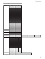
Command List
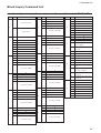
Command List (2/4)
Command Set
CAM_WB
CAM_RGain
CAM_BGain
CAM_AE
Command
Command Packet
Comments
Auto
8x 01 04 35 00 FF
Normal Auto
Indoor
8x 01 04 35 01 FF
Indoor mode
Outdoor
8x 01 04 35 02 FF
Outdoor mode
One Push WB
8x 01 04 35 03 FF
One Push WB mode
ATW
8x 01 04 35 04 FF
Auto Tracing White Balance
Manual
8x 01 04 35 05 FF
Manual Control mode
One Push Trigger
8x 01 04 10 05 FF
One Push WB Trigger
Manual Control of R Gain
Reset
8x 01 04 03 00 FF
Up
8x 01 04 03 02 FF
Down
8x 01 04 03 03 FF
Direct
8x 01 04 43 00 00 0p 0q FF
pq: R Gain
Reset
8x 01 04 04 00 FF
Manual Control of B Gain
Up
8x 01 04 04 02 FF
Down
8x 01 04 04 03 FF
Direct
8x 01 04 44 00 00 0p 0q FF
pq: B Gain
Full Auto
8x 01 04 39 00 FF
Automatic Exposure mode
Manual
8x 01 04 39 03 FF
Manual Control mode
Shutter Priority
8x 01 04 39 0A FF
Shutter Priority Automatic Exposure mode
Iris Priority
8x 01 04 39 0B FF
Iris Priority Automatic Exposure mode
Bright
8x 01 04 39 0D FF
Bright Mode (Manual control)
CAM_SlowShutter
Auto
8x 01 04 5A 02 FF
Auto Slow Shutter ON/OFF
Manual
8x 01 04 5A 03 FF
CAM_Shutter
Reset
8x 01 04 0A 00 FF
Up
8x 01 04 0A 02 FF
Down
8x 01 04 0A 03 FF
Direct
8x 01 04 4A 00 00 0p 0q FF
pq: Shutter Position
Reset
8x 01 04 0B 00 FF
Iris Setting
Up
8x 01 04 0B 02 FF
CAM_Iris
CAM_Gain
CAM_Bright
CAM_ExpComp
CAM_Backlight
CAM_SpotAE
Shutter Setting
Down
8x 01 04 0B 03 FF
Direct
8x 01 04 4B 00 00 0p 0q FF
pq: Iris Position
Reset
8x 01 04 0C 00 FF
Gain Setting
Up
8x 01 04 0C 02 FF
Down
8x 01 04 0C 03 FF
Direct
8x 01 04 4C 00 00 0p 0q FF
pq: Gain Position
Reset
8x 01 04 0D 00 FF
Bright Setting
Up
8x 01 04 0D 02 FF
Down
8x 01 04 0D 03 FF
Direct
8x 01 04 4D 00 00 0p 0q FF
pq: Bright Position
On
8x 01 04 3E 02 FF
Exposure Compensation ON/OFF
Off
8x 01 04 3E 03 FF
Reset
8x 01 04 0E 00 FF
Up
8x 01 04 0E 02 FF
Exposure Compensation Amount Setting
Down
8x 01 04 0E 03 FF
Direct
8x 01 04 4E 00 00 0p 0q FF
pq: ExpComp Position
On
8x 01 04 33 02 FF
Back Light Compensation ON/OFF
Off
8x 01 04 33 03 FF
On
8x 01 04 59 02 FF
Off
8x 01 04 59 03 FF
Position
8x 01 04 29 0p 0q 0r 0s FF
Spot Automatic Exposure Setting
pq: X (0 to F), rs: Y (0 to F)
40
Command List
Command List (3/4)
Command Set
Command
CAM_Aperture
CAM_LR_Reverse
CAM_Freeze
CAM_PictureEffect
CAM_PictureFlip
CAM_Memory
CAM_CUSTOM
Command Packet
Comments
Reset
8x 01 04 02 00 FF
Aperture Control
Up
8x 01 04 02 02 FF
Down
8x 01 04 02 03 FF
Direct
8x 01 04 42 00 00 0p 0q FF
pq: Aperture Gain
On
8x 01 04 61 02 FF
Mirror Image ON/OFF
Off
8x 01 04 61 03 FF
On
8x 01 04 62 02 FF
Off
8x 01 04 62 03 FF
Off
8x 01 04 63 00 FF
B&W
8x 01 04 63 04 FF
On
8x 01 04 66 02 FF
Off
8x 01 04 66 03 FF
Reset
8x 01 04 3F 00 0p FF
Set
8x 01 04 3F 01 0p FF
Recall
8x 01 04 3F 02 0p FF
Reset
8x 01 04 3F 00 7F FF
Still Image ON/OFF
Picture Effect Setting
Picture flip ON/OFF
p: Memory Number (=0 to 5)
Starts in this mode at Power ON.
Set
8x 01 04 3F 01 7F FF
Recall
8x 01 04 3F 02 7F FF
CAM_MemSave
Write
8x 01 04 23 0X 0p 0p
X: 00 to 07 (Address) Total 16 Byte
0q 0q FF
ppqq: 0x0000 to 0xFFFF (Data)
CAM_Display
On
8x 01 04 15 02 FF
Display ON/OFF
(8x 01 06 06 02 FF)
Off
8x 01 04 15 03 FF
(8x 01 06 06 03 FF)
On/Off
8x 01 04 15 10 FF
(8x 01 06 06 10 FF)
CAM_Title
Title Set1
Title Set2
8x 01 04 73 00 mm nn pp
mm: Vposition, nn: Hposition
qq 00 00 00 00 00 00 FF
pp: Color, qq: Blink
8x 01 04 73 01 mm nn pp
mnpqrstuvw: Setting of Display Characters
qq rr ss tt uu vv ww FF
Title Set3
8x 01 04 73 02 mm nn pp
qq rr ss tt uu vv ww FF
CAM_Mute
(1st to 10st Character)
mnpqrstuvw: Setting of Display Characters
(11th to 20th Character)
Title Clear
8x 01 04 74 00 FF
Title Setting Clear
On
8x 01 04 74 02 FF
Title Display ON/OFF
Off
8x 01 04 74 03 FF
On
8x 01 04 75 02 FF
Off
8x 01 04 75 03 FF
On/Off
8x 01 04 75 10 FF
Mute ON/OFF
41
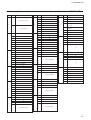
Command List
Command List (4/4)
Command Set
Command
Command Packet
Comments
CAM_PrivacyZone
SetMask
8x 01 04 76 mm nn
0r 0r 0s 0s FF
mm: Mask Settings
nn 00: Modify, 01: New
rr: W, ss:H
Display
8x 01 04 77 pp pp pp pp FF
Mask Display ON/OFF
pp pp pp pp: Mask Settings (0: OFF, 1: ON)
SetMask Color
8x 01 04 78 pp pp pp pp
qq rr FF
pp pp pp pp: Mask Color Settings
qq: “0” Color Settings
rr: “1” Color Settings
SetPan TiltAngle
8x 01 04 79 0p 0p 0p
Pan/Tilt Angle Settings
0q 0q 0q FF
ppp: Pan
qqq: Tilt
SetPTZMask
8x 01 04 7B mm 0p 0p 0p
Pan/Tilt/Zoom Settings for Mask
0q 0q 0q 0r 0r 0r 0r FF
mm: Mask Setings
ppp: Pan, qqq: Tilt, rrrr: Zoom
Non_InterlockMask
CAM_KeyLock
8x 01 04 6F mm
mm: Non-Interlock Mask Settings
0p 0p 0q 0q 0r 0r 0s 0s FF
pp: X, qq: Y, rr: W, ss: H
GridOn
8x 01 04 7C 02 FF
Grid Display On
GridOff
8x 01 04 7C 03 FF
Grid/Center Line Display Off
Off
8x 01 04 17 00 FF
Camera Control Enable/Disable
On
8x 01 04 17 02 FF
CAM_IDWrite
CAM_Alarm
On
8x 01 04 22 0p 0q 0r 0s FF
pqrs: Camera ID (=0000 to FFFF)
8x 01 04 6B 02 FF
Alarm ON/OFF
Off
8x 01 04 6B 03 FF
SetMode
8x 01 04 6C pp FF
PP: Mode Settings
00 Focus Move Detection (The rest position is fixed.)
01 Focus Move Detection (The rest position is reset.)
02 AE Move Detection (The rest value is fixed.)
03 AE Move Detection (The rest value is reset.)
0C Day/Night detection
8x 01 04 6D 0p 0p 0p 0q 0q 0q FF
ppp: Day Detect Level Setting
qqq: Night Detect Level Setting
Alarm (Reply)
y0 07 04 6B 01 FF
Detect Level “Low” t ”High”
y0 07 04 6B 00 FF
Detect Level “High” t ”Low”
On
8x 01 04 69 02 FF
ZoomPos continuous ON/OFF
Off
8x 01 04 69 03 FF
(Reply)
y0 07 04 69 0p 0p 0q 0q 0q 0q FF
pp: FD-Zoom Position
* 00 setting when mode is Combine
qqqq: Zoom Position
CAM_ReplyIntervalTimeSet
8x 01 04 6A 00 00 0p 0p FF
pp: Interval Time [V timing]
CAM_RegisterValue
8x 01 04 24 mm 0p 0p FF
mm: Register # (=00-7F)
pp: Register Value (=00-FF)
…
SetDayNightLevel
CAM_ContinuesZoomPosReply
42
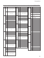
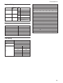
Command List
Inquiry Command List (1/2)
Inquiry Command
Command Packet
CAM_PowerInq
8x 09 04 00 FF
Inquiry Packet
Comments
y0 50 02 FF
On
y0 50 03 FF
Off
CAM_ZoomPosInq
8x 09 04 47 FF
y0 50 0p 0q 0r 0s FF
pqrs: Zoom Position
CAM_FocusModeInq
8x 09 04 38 FF
y0 50 02 FF
Auto Focus
y0 50 03 FF
Manual Focus
CAM_FocusPosInq
8x 09 04 48 FF
y0 50 0p 0q 0r 0s FF
pqrs: Focus Position
CAM_FocusNearLimitInq
8x 09 04 28 FF
y0 50 0p 0q 0r 0s FF
pqrs: Focus Near Limit Position
CAM_AFSensitivityInq
8x 09 04 58 FF
y0 50 02 FF
AF Sensitivity Normal
y0 50 03 FF
AF Sensitivity Low
y0 50 00 FF
Normal AF
CAM_AFModeInq
8x 09 04 57 FF
y0 50 01 FF
Interval AF
y0 50 02 FF
Zoom Trigger AF
CAM_AFTimeSettingInq
8x 09 04 27 FF
y0 50 0p 0q 0r 0s FF
pq: Movement Time, rs: Interval
CAM_WBModeInq
8x 09 04 35 FF
y0 50 00 FF
Auto
y0 50 01 FF
In Door
y0 50 02 FF
Out Door
y0 50 03 FF
One Push WB
y0 50 04 FF
ATW
y0 50 05 FF
Manual
CAM_RGainInq
8x 09 04 43 FF
y0 50 00 00 0p 0q FF
pq: R Gain
CAM_BGainInq
8x 09 04 44 FF
y0 50 00 00 0p 0q FF
pq: B Gain
CAM_AEModeInq
8x 09 04 39 FF
y0 50 00 FF
Full Auto
y0 50 03 FF
Manual
CAM_SlowShutterModeInq
8x 09 04 5A FF
y0 50 0A FF
Shutter Priority
y0 50 0B FF
Iris Priority
y0 50 0D FF
Bright
y0 50 02 FF
Auto
y0 50 03 FF
Manual
CAM_ShutterPosInq
8x 09 04 4A FF
y0 50 00 00 0p 0q FF
pq: Shutter Position
CAM_IrisPosInq
8x 09 04 4B FF
y0 50 00 00 0p 0q FF
pq: Iris Position
CAM_GainPosInq
8x 09 04 4C FF
y0 50 00 00 0p 0q FF
pq: Gain Position
CAM_BrightPosInq
8x 09 04 4D FF
y0 50 00 00 0p 0q FF
pq: Bright Position
CAM_ExpCompModeInq
8x 09 04 3E FF
CAM_ExpCompPosInq
8x 09 04 4E FF
CAM_BacklightModeInq
8x 09 04 33 FF
CAM_SpotAEModeInq
8x 09 04 59 FF
y0 50 02 FF
On
y0 50 03 FF
Off
y0 50 00 00 0p 0q FF
pq: ExpComp Position
y0 50 02 FF
On
y0 50 03 FF
Off
y0 50 02 FF
On
y0 50 03 FF
Off
CAM_SpotAEPosInq
8x 09 04 29 FF
y0 50 0p 0q 0r 0s FF
pq: X position, rs: Y position
CAM_ApertureInq
8x 09 04 42 FF
y0 50 00 00 0p 0q FF
pq: Aperture Gain
43
Command List
Inquiry Command List (2/2)
Inquiry Command
Command Packet
CAM_LR_ReverseModeInq
8x 09 04 61 FF
Inquiry Packet
Comments
y0 50 02 FF
On
y0 50 03 FF
Off
y0 50 02 FF
On
y0 50 03 FF
Off
y0 50 00 FF
Off
CAM_FreezeModeInq
8x 09 04 62 FF
CAM_PictureEffectModeInq
8x 09 04 63 FF
y0 50 04 FF
B&W
CAM_PictureFlipModeInq
8x 09 04 66 FF
y0 50 02 FF
On
y0 50 03 FF
Off
CAM_MemoryInq
8x 09 04 3F FF
y0 50 pp FF
pp: Last Recall Memory No.
CAM_MemSaveInq
8x 09 04 23 0X FF
y0 50 0p 0p 0q 0q FF
X: 00 to 07 (Address)
CAM_DisplayModeInq
8x 09 04 15 FF
y0 50 02 FF
On
ppqq: 0x0000 to 0xFFFF (Data)
(8x 09 06 06 FF)
y0 50 03 FF
Off
CAM_TitleDisplayModeInq
8x 09 04 74 FF
y0 50 02 FF
On
y0 50 03 FF
Off
CAM_MuteModeInq
8x 09 04 75 FF
y0 50 02 FF
On
y0 50 03 FF
Off
CAM_PrivacyDisplayInq
8x 09 04 77 FF
y0 50 pp pp pp pp FF
pp pp pp pp: Mask Display (0: OFF, 1: ON)
CAM_PrivacyPanTiltInq
8x 09 04 79 FF
y0 50 0p 0p 0p 0q 0q 0q FF
ppp: Pan
qqq: Tilt
CAM_PrivacyPTZInq
8x 09 04 7B mm FF
y0 50 0p 0p 0p 0q 0q 0q 0r 0r 0r 0r FF
mm: Mask Settings
ppp: Pan
qqq: Tilt
rrrr: Zoom
CAM_PrivacyMonitorInq
8x 09 04 6F FF
y0 50 pp pp pp pp FF
pp pp pp pp: Mask is displayed now
CAM_KeyLockInq
8x 09 04 17 FF
y0 50 00 FF
Off
y0 50 02 FF
On
CAM_IDInq
8x 09 04 22 FF
y0 50 0p 0q 0r 0s FF
pqrs: Camera ID
CAM_VersionInq
8x 09 00 02 FF
y0 50 00 20
mn pq rs tu vw FF
mnpq: Model Code (04xx)
rstu: ROM version
vw: Socket Number (=02)
CAM_AlarmInq
8x 09 04 6B FF
y0 50 02 FF
y0 50 03 FF
On
Off
CAM_AlarmModeInq
8x 09 04 6C FF
y0 50 pp FF
pp: Alarm Mode
CAM_AlarmDayNightLevelInq
8x 09 04 6D FF
y0 50 0p 0p 0p 0p 0q 0q 0q 0r 0r 0r FF
ppp: Day Detect Level
qqq: Night Detect Level
rrr: Current AE Level
CAM_AlarmDetectLevelInq
8x 09 04 6E FF
CAM_ContinuesZoomPosReplyModeInq
8x 09 04 69 FF
y0 50 01 FF
Detect Level “High”
y0 50 00 FF
Detect Level “Low”
y0 50 02 FF
On
y0 50 03 FF
Off
CAM_ReplyIntervalTimeInq
8x 09 04 6A FF
y0 50 00 00 0p 0p FF
pp: Interval Time
CAM_RegisterValueInq
8x 09 04 24 mm FF
y0 50 0p 0p FF
mm: Register #
pp: Register Value
44
Command List
Block Inquiry Command List
Lens Control System Inquiry Commands .............. Command Packet 8x 09 7E 7E 00 FF
Byte
7
Bit
7
Comments
0
6
6
Bit
5
0
Comments
Byte
Destination Address
4
6
3
2
1
1
2
0
5
0
5
0
4
0
4
0
3
0
2
0
1
0
12
3
Focus Near Limit (H)
0
0 Completion Message (50h)
0
0
7
0
7
0
6
0
6
0
5
0
5
5
0
4
0
4
0: Normal 1: Interval
4
1
3
2: Zoom Trigger
3
0
2
2
2
0
1
AF Sensitivity 0: Slow
1: Normal
1
0
0
1
0
0
0
7
0
0
Focus Mode 0:Manual 1:Auto
7
0
6
0
7
0
6
0
5
0
6
0
5
0
4
0
5
0
4
0
7
8
Focus Near Limit (L)
3
1
Zoom Position (HH)
13
3
2
3
14
7
0
7
0
6
0
6
0
5
0
5
0
4
0
9
4
2
2
1
1
Zoom Position (HL)
0
Focus Position (HL)
0
0
7
0
7
0
6
0
6
0
5
0
5
0
4
0
4
0
10
2
1
3
2
3
1
Zoom Position (LH)
0
7
0
6
0
6
0
5
0
5
0
4
0
4
0
1
11
Camera Memory Recall 1:
Executing 0: Stopped
1
Focus Command 1: Executing
15
0
Zoom Command 1: Executing
0: Stopped
7
1 Terminator (FFh)
6
1
5
1
4
1
3
1
2
1
1
1
0
1
3
2
1
Zoom Position (LL)
2
0
7
2
Low Contrast Detection 1: Yes
0: No
Focus Position (LH)
0
3
0
3
0: Stopped
3
3
0
4
Focus Position (HH)
0
0
5
6
1
1
4
0
0
6
2
3
Comments
7
1
0
7
Bit
2
Source Address
Byte
Focus Position (LL)
0
0
45
Command List
Camera Control System Inquiry Commands ......... Command Packet 8x 09 7E 7E 01 FF
Byte
Bit
Comments
Byte
6
0
5
0
4
0
4
0
3
3
0
2
2
Destination Address
4
6
Source Address
1
3
2
WB Mode
1
Gain Position
0
7
7
0
7
0
0 Completion Message (50h)
0
6
0
6
0
6
1
5
0
5
0
5
0
4
0
4
1
3
0
2
2
0
1
1
0
0
0
0
7
0
7
0
7
0
6
0
6
0
6
0
5
0
5
0
5
0
4
4
0
4
0
7
8
2
1
4
3
2
Aperture Gain
Bright Position
1
0
14
3
2
R Gain (H)
13
3
3
Exposure Mode
3
2
1
0
Exposure Comp. Position
0
7
0
7
1 Terminator (FFh)
7
0
6
0
6
1
6
0
5
0
5
1
5
0
4
0
4
1
9
15
3
Spot AE 1: On 0: Off
3
1
3
2
Back Light 1:On 0:Off
2
1
2
1
Exposure Comp. 1:On 0:Off
1
1
0
Slow Shutter 1:Auto 0:Manual
0
1
7
0
4
1
0
R Gain (L)
0
7
0
6
0
6
0
5
0
5
0
4
4
0
10
3
3
2
2
1
1
B Gain (H)
Shutter Position
0
0
5
12
0
0
4
Comments
0
1
3
Bit
5
1
2
6
Byte
0
5
1
Comments
0
0
6
0
Bit
7
7
7
7
0
7
0
6
0
6
0
5
0
5
0
4
0
1
4
3
2
3
2
11
Iris Position
1
B Gain (L)
0
46
Command List
Other Inquiry Commands ........................................ Command Packet 8x 09 7E 7E 02 FF
Byte
Bit
Bit
Comments
Bit
Comments
7
7
0
7
0
6
6
0
6
0
5
0
5
4
0
4
3
0
2
0
1
0
0
0
2
0
7
0
1
0
6
0
0
5
0
7
0
4
0
6
0
3
0
5
0
2
0
4
0
5
0
Comments
Destination Address
4
6
3
2
1
Byte
Source Address
0
7
1
2
6
1
5
0
3
Clock 1: Provided 0: Not
provided
Frame rate 1:25fps, 0:29.97fps
3
0
2
0
1
0
3
1
0
0
0
2
0
0
7
0
1
7
0
6
0
0
6
0
5
0
7
0
5
0
0
6
0
5
0
4
0
4
0
3
0
8
4
3
2
0
13
1
Camera ID (HH)
14
0
3
2
1
Key Lock 1: On 0: Off
0
0
Power 1:On 0:Off
7
0
1
0
7
0
6
0
0
6
0
5
0
7
0
6
1
3
5
1
2
4
1
3
1
0
2
1
1
1
4
3
2
1
0
0
9
Freeze 1:On 0:Off
LR Reverse 1:On 0:Off
4
1
0
Camera ID (HL)
15
0
0
7
0
1
7
0
6
0
0
5
0
4
0
6
5
provided
1
5
4
7
12
0
Memory 1: Provided 0: Not
4
2
3
0 Completion Message (50h)
Byte
0
5
Privacy Zone 1: On 0: Off
4
Mute 1: On 0: Off
3
Title Display 1: On 0: Off
2
2
Display 1: On 0: Off
1
10
3
Camera ID (LH)
1
0
0
0
0
7
0
7
0
6
0
6
0
5
0
5
0
4
0
4
0
3
2
1
11
3
2
Picture Effect Mode
1 Terminator (FFh)
1
Camera ID (LL)
0
0
47
Command List
Enlargement Function Query Command ............... Command Packet 8x 09 7E 7E 03 FF
Byte
Bit
Comments
Byte
7
6
0
6
0
0
5
0
4
4
0
4
0
6
11
3
2
Source Address
1
1
0
0
0 Completion Message (50h)
3
7
0
1
6
0
5
0
5
0
4
1
4
0
3
0
7
0
2
1
0
1
0
0
0
AF Interval Time (L)
7
0
7
0
6
0
6
0
5
0
5
0
4
0
4
0
8
0
1
1
0
0
SpotAE Position (X)
7
0
7
0
6
0
6
0
5
0
5
0
4
0
4
0
9
3
13
3
2
0
1
1
0
0
SpotAE Position (Y)
7
0
7
0
6
0
6
0
5
0
5
0
4
0
4
0
3
0
2
0
1
1
Alarm (1: On, 0: Off)
0
0
Picture flip (1: On, 0: Off)
10
3
2
12
3
2
AF Activation Time (H)
7
0
6
0
5
0
4
0
0
Advanced Privacy (1:
Provided, 0: Not provided)
3
2
2
2
AF Interval Time (H)
6
2
5
0
0
Destination Address
3
4
Comments
7
Byte
5
7
3
Bit
0
6
2
2
Comments
7
5
3
1
Bit
14
1
Alarm (1: Provided, 0: Not
provided)
0
Picture flip (1: Provided, 0:
Not provided)
7
0
6
0
5
0
4
0
3
0
2
0
1
0
0
0
7
0
6
0
5
0
4
0
3
0
2
0
1
0
0
0
7
0
6
0
5
0
4
0
3
0
2
0
1
0
0
0
7
15
1 Terminator (FFh)
6
1
5
1
4
1
3
1
2
1
1
1
0
1
3
2
AF Activation Time (L)
1
0
48
Command List
VISCA Command Setting Values
Exposure Control (1/2)
30 fps
Shutter Speed
Iris
25 fps
15
10000
10000
14
6000
6000
13
4000
3500
12
3000
2500
11
2000
1750
10
1500
1250
0F
1000
1000
0E
725
600
0D
500
425
0C
350
300
0B
250
215
0A
180
150
09
125
120
08
100
100
07
90
75
06
60
50
05
30
25
04
15
12
03
8
6
02
4
3
01
2
2
00
1
1
11
F1.8
10
F2.0
0F
F2.4
0E
F2.8
0D
F3.4
0C
F4.0
0B
F4.8
0A
F5.6
09
F6.8
08
F8.0
07
F9.6
06
F11
05
F14
04
F16
03
F19
02
F22
01
F28
00
CLOSE
Gain
0F
28 dB
0E
26 dB
0D
24 dB
0C
22 dB
0B
20 dB
0A
18 dB
09
16 dB
08
14 dB
07
12 dB
06
10 dB
05
8 dB
04
6 dB
03
4 dB
02
+2 dB
01
0
00
–3 dB
49
Command List
Exposure Control (2/2)
Zoom Ratio and Zoom Position
(for reference)
IRIS
Bright
Exposure Comp.
GAIN
1F
F1.8
28 dB
1E
F1.8
26 dB
Zoom Ratio
×10 Lens
Optical Zoom
Position Data
1D
F1.8
24 dB
×1
0000
1C
F1.8
22 dB
×2
19FE
1B
F1.8
20 dB
×3
254E
1A
F1.8
18 dB
×4
2C4A
19
F1.8
16 dB
×5
3160
18
F1.8
14 dB
×6
3572
17
F1.8
12 dB
×7
38E0
16
F1.8
10 dB
×8
3BCA
15
F1.8
8 dB
×9
3E2A
14
F1.8
6 dB
×10
4000
13
F1.8
4 dB
12
F1.8
2 dB
11
F1.8
0
10
F2.0
0
Lens Control
0F
F2.4
0
1000: Over Inf
0E
F2.8
0
2000: 4 m
0D
F3.4
0
3000: 3 m
0C
F4.0
0
4000: 2 m
5000: 1.4 m
0B
F4.8
0
0A
F5.6
0
09
F6.8
0
08
F8.0
0
07
F9.6
0
06
F11
0
05
F14
0
04
F16
0
03
F19
0
02
F22
0
01
F28
0
00
CLOSE
0
0E
7
10.5 dB
0D
6
9 dB
0C
5
7.5 dB
0B
4
6 dB
0A
3
4.5 dB
09
2
3 dB
08
1
1.5 dB
07
0
0 dB
06
–1
–1.5 dB
05
–2
–3 dB
04
–3
–4.5 dB
03
–4
–6 dB
02
–5
–7.5 dB
01
–6
–9 dB
00
–7
–10.5 dB
Focus Near Limit
As the distance on the left
will differ due to temperature
6000: 1 m
characteristics, etc., use as
7000: 50 cm
approximate values.
8000: 20 cm
9000: 10 cm
* The lower 1 byte is fixed at
00.
A000: 5 cm
B000: 2.2 cm
C000: 1 cm
50
Command List
Mask Setting
MASK set
Size of Mask
Mask of Offset
Mask Bit
MASK Display color
Mask_A
00
Mask_B
01
Mask_C
02
Mask_D
03
Mask_E
04
Mask_F
05
Mask_G
06
Mask_H
07
Mask_I
08
Mask_J
09
Mask_K
0A
Mask_L
0B
Mask_M
0C
Mask_N
0D
Mask_O
0E
Mask_P
0F
Mask_Q
10
Mask_R
11
Mask_S
12
Mask_T
13
Mask_U
14
Mask_V
15
Mask_W
16
Mask_X
17
Width (W)
00 ~ 50
High (H)
00 ~ 3C
H Position (X)
B0 ~ 50
V Position (Y)
C4 ~ 3C
Bit
7 6 5 4 3 2 1 0
7 6 5 4 3 2 1 0
7 6 5 4 3 2 1 0
7 6 5 4 3 2 1 0
Mask
- - X W V U T S
- - R Q P O N M
- - L K J I H G
- - F E D C B A
Black
00
10
Gray1
01
11
Gray2
02
12
Gray3
03
13
Gray4
04
14
Gray5
05
15
Gray6
06
16
White
07
17
Red
08
18
Green
09
19
Blue
0A
1A
Cyan
0B
1B
Yellow
0C
1C
Magenta
0D
1D
Mosaic
PTZ angle
7F
Angle
–180º
~ –90º
~ 0º
~ 90º
~ 180º
Set
800
~ C00
~ 000
~ 400
~ 800
51
Command List
Register Setting
00
Register # Value
mm
pp
VISCA Baud Rate
00
Frame Rate
70
Image Out mode
71
01
02
03
04
05
06
07
A
B
C
D
E
F
G
H
08
09
0a
0b
0c
0d
0e
0f
I
J
K
L
M
N
O
P
00
9600 bps
10
11
12
13
14
15
16
17
01
19200 bps
Q
R
S
T
U
V
W
X
02
38400 bps
18
19
1a
1b
1c
1d
1e
1f
01
29.97 fps
Y
Z
&
?
!
1
2
02
25 fps
20
21
22
24
25
26
27
01
Progressive
3
4
5
6
7
8
9
0
02
Interlace
(Only REC656 mode)
28
29
2a
2b
2c
2d
2e
2f
À
È
Ì
Ò
Ù
Á
É
Í
30
31
32
33
34
35
36
37
Ó
Ú
Â
Ê
Ô
Æ
Œ
Ã
Others
23
38
39
3a
3b
3c
3d
3e
3f
AF Active time
00 ~ FF
Õ
Ñ
Ç
ß
Ä
Ï
Ö
Ü
AF interval time
00 ~ FF
40
41
42
43
44
45
46
47
Spot AE X table
00 ~ 0F
Å
$
F
¥
DM
£
¿
¡
Spot AE Y table
00 ~ 0F
48
49
4a
4b
4c
4d
4e
4f
R Gain
00 ~ FF
ø
“
:
‘
.
,
/
-
B Gain
00 ~ FF
Aperture
00 ~ 0F
Title Setting
Vposition
00 to 0A
Hposition
00 to 17
00: Does not blink
Blink
01: Blinks
Color
00
White
01
Yellow
02
Violet
03
Red
04
Cyan
05
Green
06
Blue
52
Specifications
Specifications
1
Image sensor
/4 type IT CCD (HAD)
Picture elements Approx. 330K pixels
(659 (H) × 494 (V))
Horizontal resolution
VGA 640 × 480
Lens
10× zoom
F= 4.2 mm (WIDE) to 42 mm
(TELE), F1.8 to F2.9
Zoom movement speed
Optical WIDE/Optical TELE 1.8 s
∞ to Near
0.5 s
Angle of view (H)
46 degree (WIDE end) to 4.6 degree
(TELE end)
Min. working distance
10 mm (WIDE end), 1000 mm
(TELE end)
Sync system
Internal
Min. illumination
2.3 lx (F1.8, 1/30 s : Typical value)
Recommended illumination
100 to 100,000 lx
S/N ratio
50 dB or more
Back light compensation
ON/OFF
Electronic shutter speed
1
/1 to 1/10,000 s (22 steps)
White balance
AUTO, ATW, Indoor, Outdoor,
One Push WB, Manual WB
Gain
Auto/Manual (–3 to 28 dB, 2 dB
steps)
Aperture control 16 steps
Preset
6-POSITIONS
Serial interface VISCA protocol (TTL/CMOS)
9.6 Kbps, 19.2 Kbps, 38.4 Kbps,
Stop bit, 1/2 bit
Video Output
YUV 4:2:2 (16 bit or 8 bit)
See the following pages for the
timing chart.
Storage temperature/Humidity
–20 to 60 °C (–4 to 140 °F)/20 to 95 %
Operating temperature/Humidity
0 to 50 °C (32 to 122 °F)/20 to 80 %
Power requirements/Power consumption
6 to 12 V DC/1.5 W (2.7 W)
Weight
84 g (3 oz.)
Dimensions
37.3 × 43.8 × 61 mm
(1 1/2 × 1 3/4 × 2 1/2 in.) (w/h/d)
Design and specifications are subject to change
without notice.
53
Specifications
Timing Charts
DIGITAL Port Interface
54
Specifications
Output Timing (Rec601 Progressive)
* 29.97 fps/25 fps
Output Timing (Rec656 Progressive)
* 29.97 fps/25 fps
55
Specifications
Output Timing (Rec656 Interlace)
* 29.97 fps/25 fps
DIGITAL Image Output Y, Cr, Cb 4:2:2 FORMAT
56
Specifications
External Dimensions
Front
Top
Right side
Left side
Bottom
(Tripod screw for camera)
Within a depth of 7 mm (9/32 in.) or less
form the bottom surface
Back
Within a depth of 3 mm
(1/8 in.) or less form the side
57
Specifications
Pin Assignment
CN501
CN701
24P FFC (0.5mm)
KYOCERA ELCO Co. 046240024006848+
4P connector
J.S.T. Mfg Co. S4B-ZR-SM4A-TF(LF)
Pin No. Name 16 bit data bus Level
8 bit data bus Level
Pin No.
Name
Level
1
GND Signal Ground
1
UNREG
Power Input
2
Y0
Digital Y-Out 0 0 - 3.2 Vp-p Digital Out 0 0 - 3.2 Vp-p
2
GND
Ground
3
Y1
Digital Y-Out 1 0 - 3.2 Vp-p Digital Out 1 0 - 3.2 Vp-p
3
TD
TTL Level (0 - 5.0 Vp-p)
4
Y2
Digital Y-Out 2 0 - 3.2 Vp-p Digital Out 2 0 - 3.2 Vp-p
4
RD
TTL Level (0 - 5.0 Vp-p)
5
Y3
Digital Y-Out 3 0 - 3.2 Vp-p Digital Out 3 0 - 3.2 Vp-p
6
Y4
Digital Y-Out 4 0 - 3.2 Vp-p Digital Out 4 0 - 3.2 Vp-p
7
Y5
Digital Y-Out 5 0 - 3.2 Vp-p Digital Out 5 0 - 3.2 Vp-p
8
Y6
Digital Y-Out 6 0 - 3.2 Vp-p Digital Out 6 0 - 3.2 Vp-p
9
Y7
Digital Y-Out 7 0 - 3.2 Vp-p Digital Out 7 0 - 3.2 Vp-p
10
GND Signal Ground
11
C0
Digital C-Out 0 0 - 3.2 Vp-p Hi imp
12
C1
Digital C-Out 1 0 - 3.2 Vp-p Hi imp
13
C2
Digital C-Out 2 0 - 3.2 Vp-p Hi imp
14
C3
Digital C-Out 3 0 - 3.2 Vp-p Hi imp
15
C4
Digital C-Out 4 0 - 3.2 Vp-p Hi imp
16
C5
Digital C-Out 5 0 - 3.2 Vp-p Hi imp
17
C6
Digital C-Out 6 0 - 3.2 Vp-p Hi imp
18
C7
Digital C-Out 7 0 - 3.2 Vp-p Hi imp
19
GND Signal Ground
20
VSYNC Vertical SYNC 0 - 3.2 Vp-p
0 - 3.2 Vp-p
21
HSYNC Horizontal SYNC 0 - 3.2 Vp-p
0 - 3.2 Vp-p
22
GND Signal Ground
23
CLOCK Clock signal
24
GND Signal Ground
0 - 3.2 Vp-p
6 - 12 V (dc)
0 - 3.2 Vp-p
58