1
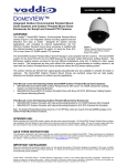
Installation and User Guide
Camera and Electronic Products for Integrators
CEILINGVIEW™ SD CCU
Ceiling Mounted Document Camera System with CCU
OVERVIEW:
The Vaddio™ CeilingVIEW SD CCU (Figure 1) is a Standard
Definition ceiling Document Camera designed for use with
videoconferencing codecs, monitors and presentation
applications where image quality and resolution are critical. The
CeilingVIEW SD CCU can be configured for 4:3 standard
definition video with Y/C and composite video outputs.
Equipped with a 36x optical motorized zoom lens and 12X
digital zoom range, the camera has a 432x total zoom
capability. The ¼” CCD image sensor has approximately
380,000 pixels. The heart of the CCU system is its ability to
adjust red and blue gain, aperture, as well as iris and gain of the
camera module.
Figure 1: CeilingVIEW CCU (above left);
CeilingVIEW SD Document Camera (above).
Vaddio’s active cabling system uses high speed differential signaling (HSDS) for video signals from the
camera module to the Quick-Connect™ CV HD/SD interface as opposed to baluns. HSDS gives this system
superior video quality over CAT-5 cabling and the ability to adjust the video signal depending on the length of
the cabling used. The EZCamera series cabling system delivers video up to 400 feet over standard CAT-5
cable. The Quick-Connect CCU connects directly to the RS-232 port on the camera module. RS-232 from
an external device, such as Vaddio’s ProductionVIEW FX, or an external control system can be used in-line.
The CeilingVIEW SD CCU is unmatched for price and performance as compared to other ceiling mounted
document cameras available today.
INTENDED USE:
Before operating the CeilingVIEW SD CCU system, please read the entire manual thoroughly. The
CeilingVIEW SD CCU Document Camera was designed, built and tested for use indoors and with the
provided power supply. The use of a power supply other than the one provided or outdoor operation has not
been tested and could damage the electronics and/or create a potentially unsafe operating condition.
SAVE THESE INSTRUCTIONS:
The information contained in this manual will help you install and operate your Vaddio CeilingVIEW SD. If
these instructions are misplaced, Vaddio keeps copies of Specifications, Installation and User Guides and
most pertinent product drawings for the Vaddio product line on the website. These documents can be
downloaded from www.vaddio.com free of charge.
IMPORTANT SAFEGUARDS:
Read and understand all instructions before using. Do not operate the system if it has been dropped or
damaged. In this case, a Vaddio technician must examine the product before operating. To reduce the risk
of electric shock, do not immerse in water or other liquids and avoid extremely humid conditions.
Use only the power supply (or power supplies) provided with the CeilingVIEW. Use
of any unauthorized power supply will void any and all warranties.
ⓒ2008 Vaddio - CeilingVIEW SD CCU- All Rights Reserved. Reproduction in whole or in part without written permission is prohibited. Specifications and
pricing are subject to change without notice. Vaddio, CeilingVIEW, EZCamera, Quick-Connect, WallVIEW, EZCable and PowerRite are trademarks of
Vaddio, Inc. All other trademarks are property of their respective owners. Document 341-769 RevA.
CeilingVIEW SD CCU
UNPACKAGING – SYSTEM COMPONENT LISTS
Carefully remove all parts from the packaging and identify the following parts:
CeilingVIEW SD, Part Number 999-2009-000 (NTSC) includes:
• One (1) CeilingVIEW SD Camera Enclosure
• One (1) CeilingVIEW Camera Control Unit
• One (1) White Trim Ring with two (2) white screws
• One (1) Vaddio IR Remote Controller
• One (1) Quick-Connect CV HD/SD Interface
• One (1) PowerRite 36VDC, 2.78A Power Supply (for Quick-Connect CCU)
• One (1) PowerRite 24VDC, 2A Power Supply (for Quick-Connect CV HD/SD)
• One (1) 2-position Phoenix Type Connector (Tally port on CCU)
• Two (2) Adjustable ceiling tile support rails with two (2) knurled knobs
• One (1) RJ-45 to DB9 EZCamera Control Adapter (998-1001-232)
• One (1) AC Cord Set for North America
• Installation and User Guide (341-769)
CeilingVIEW SD, Part Number 999-2009-001 (PAL) includes:
• One (1) CeilingVIEW SD Camera Enclosure
• One (1) CeilingVIEW Camera Control Unit
• One (1) White Trim Ring with two (2) white screws
• One (1) Vaddio IR Remote Controller
• One (1) Quick-Connect CV HD/SD Interface
• One (1) PowerRite 36VDC, 2.78A Power Supply (for Quick-Connect CCU)
• One (1) PowerRite 24VDC, 2A Power Supply (for Quick-Connect CV HD/SD)
• One (1) 2-position Phoenix Type Connector (Tally port on CCU)
• Two (2) Adjustable ceiling tile support rails with two (2) knurled knobs
• One (1) RJ-45 to DB9 EZCamera Control Adapter (998-1001-232)
• One (1) Euro AC Cord
• One (1) UK AC cord Set
• Installation and User Guide (341-769)
INSTALLATION INSTRUCTIONS:
The CeilingVIEW SD CCU Document Camera is an integrated document/object camera specifically designed
for installation in a suspended ceiling tile above a conference table, lectern or work surface. Recommended
ceiling height range is between 8’ and 12’ (2.44m to 3.66m).
Before Starting the Installation
• IMPORTANT NOTE: Please review Figure 5 closely. The Quick-Connect CCU for the CeilingVIEW
document cameras utilizes only the ports shown in the figure. All Power for the Camera Module, as
well as video returned from the Camera Module is delivered via the Quick-Connect CV HD/SD, also
shown in the picture.
• Before starting the installation of the CeilingVIEW SD CCU Document Camera, check above the
ceiling where you plan to install the camera and make sure the area is clear of obstructions and
confirm that there is adequate room for the camera enclosure.
• When terminating your CAT-5 cabling, make sure that you test each cable for proper termination of
all ends with a CAT-5 continuity tester.
• All above-ceiling work must conform to local building codes and should be performed by qualified
personnel.
• The camera module enclosure and tile support rails allow for superior flexibility and positioning
freedom when used with 2’x2’ and 2’x4’ ceiling tiles. The camera does not have to be mounted in
the center of the tile.
• For cutting ease, remove the ceiling tile and place on a suitable and safe work surface.
• Because the Quick-Connect CCU is an in-line device, the CeilingVIEW SD CCU camera system is
not compatible with daisy-chain configurations. You must have a dedicated RS-232 control port
connected to the Quick-Connect CCU.
Vaddio CeilingVIEW SD CCU Installation and User Guide - Document 341-769 Rev. A
Page 2 of 16
CeilingVIEW SD CCU
Camera Module
For video reference, LED power light, IR window and Dip Switch cover will be oriented to the bottom of the
image displayed (shown in Figure 2). Take this into consideration when positioning the camera module. The
supplied mounting rails may need to be used for additional support of the camera on the ceiling tile to
distribute the weight of the camera into the grid and avoid tile warping.
Figure 2:
Top of Document Image
Camera Lens
Laser Pointer and
adjustments
IR Window
LED Power Light
Dip Switch Access Cover for IR
Remote and Image Resolution
(See Figure 6 for proper
settings)
Bottom of Document Image
Step-by-Step Assembly Instructions:
1.
2.
3.
4.
5.
Attach a string or plumb bob to the ceiling tile with a thumbtack.
Position the string directly over the table or work surface to allow easy document and object
positioning.
Using a sharp utility knife, score a 5-3/4” diameter circle into the front of the tile centered on the string.
Carefully cut out the 5-3/4” hole.
Place the tile support rails on the backside of the tile and center over the hole. Carefully place camera
into the cutout hole from the back of tile (see Figure 3).
Figure 3:
Side View of CeilingVIEW
SD Camera Enclosure
shown with Tile Supports
and Trim Ring in place.
Vaddio CeilingVIEW SD CCU Installation and User Guide - Document 341-769 Rev. A
Page 3 of 16
CeilingVIEW SD CCU
6.
Using the supplied thumbscrews and washers, attach the support rails to the CeilingVIEW camera
(see Figure 4). Place rail edge between two washers and tighten thumbscrew securely. Repeat for
the other rail. NOTE: The thumbscrew sits on top of the rail, not through the holes on the rail.
Figure 4:
Side View of CeilingVIEW
SD with Tile Support
Brace placement
7.
Two CAT-5 cables (plenum rated as building codes dictate) are run from the ceiling location where the
camera is mounted, to where the Quick-Connect Box is located near the main rack or head-end
equipment. Both SD composite and Y/C are active. Connections on the CeilingVIEW SD CCU are
shown in Figure 5.
NOTE: If you are terminating your own CAT-5 cables, make sure to test all cables with a continuity
tester to confirm proper pin-outs.
8. Next, connect the Power/Video CAT-5 cable from the Quick-Connect CV HD/SD box to the CAT-5
cable that is connected to the Power-Video port on the Camera Enclosure in the ceiling (see Figure 5).
The Quick-Connect CV HD/SD provides power to the camera, as well as delivers video back from the
camera module. Note: The Quick-Connect CV HD/SD uses a 24VDC power supply and the QuickConnect CCU uses a 36VDC power supply.
9. For RS-232 control, connect the CAT-5 cable to the Camera Enclosure, and then the other end of the
CAT-5 cable to the RS-232 output on the Quick-Connect CCU (see Figure 5). If there is an external
RS-232 controller (e.g. Vaddio’s ProductionVIEW SD, or a control system such as Crestron or AMX,
etc.) then connect a CAT-5 cable between that external controller and the RS-232 Input on the back of
the Quick-Connect CCU. An RJ-45 to DB-9 connector is supplied for DB-9 RS-232 ports.
10. NOTE: The Quick-Connect CCU will only send RS-232 commands to the camera’s image sensor. All
zoom and zoom preset commands are handled by an external controller or IR remote controls that are
compatible with CeilingVIEW SD. Pressing CCU Control on the front panel of the CCU allows the user
to adjust all of the knobs and controls on the front panel. Pressing CCU control again, allows RS-232
commands from an external control system (e.g. ProductionVIEW SD, AMX, Crestron, etc.) to pass
through to the Camera Module.
11. To finish the installation, the camera and ceiling tile should be carefully replaced in the suspended
ceiling at this time. Carefully move the trim ring into position on the bottom of the ceiling tile and
secure with the two supplied white screws.
12. With the CAT-5 cabling connected to the proper ports at both the Camera Enclosure and QuickConnect CV HD/SD interface, review the dip switch settings (Figure 6) and set the camera to output
the desired signal. Connect the Vaddio PowerRite power supply. Plug the AC cord into an outlet.
The camera zoom will home into position and the video output signals will be live and viewable after
the camera is fully initialized. To change the output resolution or any dip switch setting, first unplug
the power supply, change the dipswitch setting and re-power the Quick-Connect CV HD/SD. If using a
Polycom or TANDBERG IR Remote, set dip switches 1 & 2 accordingly to allow momentary laser
pointer on the Tilt Down command.
NOTE: Use of a power supply other than the provided Vaddio power supply for this device will void
the warranty and may cause camera and equipment damage. Make sure that the proper power
supply is connected to the Quick-Connect boxes – they are different voltages.
Vaddio CeilingVIEW SD CCU Installation and User Guide - Document 341-769 Rev. A
Page 4 of 16
CeilingVIEW SD CCU
Figure 5: System Configuration
The main components of the CeilingVIEW SD CCU are the camera module and Quick-Connect CCU and
Quick-Connect CV HD/SD interface. Basic system connectivity is outlined below. The Quick-Connect CV
HD/SD interface can be installed on the optional rack mount adapter, Part # 999-6000-002.
Controlled by RS-232,
Vaddio IR Remote and
Polycom IR Remote or
TANDBERG IR Remotes
(zoom and laser pointer)
ProductionVIEW FX
Optional:
Connection
to external
RS-232
control port
for zoom
control
Quick-Connect CCU
36 VDC
Power
Supply
SD Codec
CAT-5 Cables
Up to 400’
Power
and
Video
SD Video Output
CeilingVIEW SD
Quick-Connect CV HD/SD
24 VDC
Power
Supply
Video
Adjustments
for Distance
Controlling the Camera
A unique feature of the CeilingVIEW SD CCU allows the camera’s zoom functions (Zoom In and Out) and
intermittent laser (Tilt Down) to be controlled by either a Polycom® or TANDBERG® remote control. In
addition, the Document Camera can be used with either the Vaddio IR remote control supplied or via RS-232
using VISCA control protocol (see VISCA Command Set information at the back of the manual). The
CeilingVIEW SD CCU will respond to all three IR remotes concurrently.
Control Systems
If you are using a control system (i.e. Crestron®, AMX®, etc.) plug the Cat. 5 cable from the RS-232 IN jack
on the camera to your control system using the Cat. 5 to DB-9 serial adapter supplied with the CeilingVIEW
SD. Daisy Chain Note: Use the CeilingVIEW SD as the last camera in the control chain when daisy
chaining cameras together, as there is no RS-232 output on the Camera Module.
Vaddio CeilingVIEW SD CCU Installation and User Guide - Document 341-769 Rev. A
Page 5 of 16
CeilingVIEW SD CCU
Dip Switch Settings
Set the dipswitches to the desired signal/function and then apply power to the system. To make any
changes, remove power from the system, make the change and re-apply power to the system.
Description / Dip Switch
CeilingVIEW SD Laser Pointer “MOMENTARY ON” will be
activated by the Polycom or TANDBERG IR Remote
Controller “TILT DOWN” command
CeilingVIEW SD Laser Pointer “MOMENTARY ON” will not
be activated by the Polycom or TANDBERG IR Remote
Controller “TILT DOWN” command
Disable All Polycom and TANDBERG IR Remote
Commands
1
DN
2
UP
3
DN
4
DN
5
DN
6
DN
DN
DN
DN
DN
DN
DN
UP
*
*
*
*
*
Figure 6: Vaddio IR Remote
Programming the Remote:
1. Install 3 “AAA” batteries into the remote
2. Press and hold POWER & MIRROR for 5 seconds
Function
Description
POWER
Camera on/off
ZOOM
IN (tele)
OUT (wide)
FOCUS
AUTO:
NEAR:
FAR:
Auto Focus Mode ON
Manual Focus Near
Manual Focus Far
LASER
ON:
MOM:
On/Off toggle
Turns on Laser for five seconds
BRIGHT
UP:
DOWN:
Brightness up
Brightness down
PRESET
Six (6) presets - 0 though 5
SET
Sets Zoom Presets
W/BAL
One Touch White Balance
BKLIGHT
Back Light Compensation
B/W
Black and White Mode (color off)
POS/NEG
Positive/Negative - Art Mode
FREEZE
Freeze Frame/Image Effect
Setting Zoom Presets (Vaddio Remote):
1. Zoom the camera lens to the desired position.
2. Press and hold the SET button for one second. The blue LED will blink for approximately 5 seconds.
3. Press button labeled 0 through 5 within the 5 seconds. The Blue LED on camera will stop blinking.
4. To Recall Presets, press on the PRESET buttons labeled 0 thru 5.
Vaddio CeilingVIEW SD CCU Installation and User Guide - Document 341-769 Rev. A
Page 6 of 16
CeilingVIEW SD CCU
COMMAND LIST
Vaddio supplies this control specification for the CeilingVIEW SD Visualizer.
Communication Specifications
Communication Speed: 9600 bps (default)
Start bit:
1
Stop bit:
1
Data bits:
8
Parity:
None
Communication Example:
For the VISCA Packet “8x 01 04 07 03 FF” (CAM_Zoom_Wide), “x” corresponds with the number and order
of the camera in the control chain (daisy chain) where x = 1 for the first camera, x = 2 for the second camera,
etc…
VISCA Command Set
Command Set
Command
Command Packet
AddressSet
IF_Clear
CommandCancel
CAM_Power
Broadcast
Broadcast
88 30 01 FF
88 01 00 01 FF
8x 2p FF
8x 01 04 00 02 FF
8x 01 04 00 03 FF
8x 01 04 07 00 FF
8x 01 04 07 02 FF
8x 01 04 07 03 FF
8x 01 04 07 2p FF
8x 01 04 07 3p FF
8x 01 04 47 0p 0q 0r 0s FF
8x 01 04 06 02 FF
8x 01 04 06 03 FF
8x 01 04 36 00 FF
8x 01 04 36 01 FF
8x 01 04 06 00 FF
8x 01 04 06 2p FF
8x 01 04 06 3p FF
8x 01 04 06 10 FF
8x 01 04 46 00 00 0p 0q FF
8x 01 04 08 00 FF
8x 01 04 08 02 FF
8x 01 04 08 03 FF
8x 01 04 08 2p FF
8x 01 04 08 3p FF
8x 01 04 48 0p 0q 0r 0s FF
8x 01 04 38 02 FF
8x 01 04 38 03 FF
8x 01 04 38 10 FF
8x 01 04 18 01 FF
8x 01 04 18 02 FF
8x 01 04 28 0p 0q 0r 0s FF
8x 01 04 58 02 FF
8x 01 04 58 03 FF
8x 01 04 57 00 FF
8x 01 04 57 01 FF
8x 01 04 57 02 FF
8x 01 04 27 0p 0q 0r 0s FF
8x 01 04 47 0p 0q 0r 0s
0t 0u 0v 0w FF
8x 01 04 19 01 FF
8x 01 04 19 02 FF
8x 01 04 35 00 FF
8x 01 04 35 01 FF
8x 01 04 35 02 FF
8x 01 04 35 03 FF
8x 01 04 35 04 FF
8x 01 04 35 05 FF
8x 01 04 10 05 FF
CAM_Zoom
CAM_Dzoom
CAM_Focus
AF Sensitivity
CAM_AFMode
CAM_ZoomFocus
CAM_Initialize
CAM_WB
On
Off
Stop
Tele(Standard)
Wide(Standard
Tele(Variable)
Wide(Variable)
Direct
On
Off
Combine Mode
Separate Mode
Stop
Tele(Variable)
Wide(Variable)
X1/Max
Direct
Stop
Far(Standard)
Near(Standard)
Far(Variable)
Near(Variable)
Direct
Auto Focus
Manual Focus
Auto/Manual
One Push Trigger
Infinity
Near Limit
Normal
Low
Normal AF
Interval AF
Zoom Trigger AF
Active/Interval Time
Direct
Lens
Comp Scan
Auto
Indoor
Outdoor
One Push WB
ATW
Manual
One Push Trigger
Comments
P: Socket No. (=1or2)
Power ON/OFF
P=0 (Low) to 7 (High)
Pqrs: Zoom Position
Digital Zoom ON/OFF
Opt/Dig Zoom Combined
Opt/Dig Zoom Separate
P=0(Low) to 7 (High)
X1/MAX Maginification Switch
Pq: D-Zoom Position
P=0 (Low) to 7 (High)
Pqrs: Focus Position
AF ON/OFF
One Push AF Trigger
Forced Infinity
Pqrs: Focus Near Limit Position
AF Sensitivity High/Low
AF Movement Mode
Pq: Active Time, rs: Interval
Pqrs: Zoom Position
Tuvw: Focus Position
Lens Initialization Start
Correction of Pixel Blemishes
Normal Auto
Indoor mode
Outdoor mode
One Push WB mode
Auto Tracing White Balance
Manual Control mode
One Push WB Trigger
Vaddio CeilingVIEW SD CCU Installation and User Guide - Document 341-769 Rev. A
Page 7 of 16
CeilingVIEW SD CCU
CAM_Rgain
CAM_MemSave
Reset
Up
Down
Direct
Reset
Up
Down
Direct
Full Auto
Manual
Shutter Priority
Iris Priority
Bright
Auto
Manual
Reset
Up
Down
Direct
Reset
Up
Down
Direct
Reset
Up
Down
Direct
Reset
Up
Down
Direct
On
Off
Reset
Up
Down
Direct
On
Off
DIRECT
On
Off
Position
Reset
Up
Down
Direct
On
Off
Off
Neg.Art
B&W
On
Off
On
Off
On
Off
Reset
Set
Recall
Reset
Set
Recall
Write
8x 01 04 03 00 FF
8x 01 04 03 02 FF
8x 01 04 03 03 FF
8x 01 04 43 00 00 0p 0q FF
8x 01 04 04 00 FF
8x 01 04 04 02 FF
8x 01 04 04 03 FF
8x 01 04 44 00 00 0p 0q FF
8x 01 04 39 00 FF
8x 01 04 39 03 FF
8x 01 04 39 0A FF
8x 01 04 39 0B FF
8x 01 04 39 0D FF
8x 01 04 5A 02 FF
8x 01 04 5A 03 FF
8x 01 04 0A 00 FF
8x 01 04 0A 02 FF
8x 01 04 0A 03 FF
8x 01 04 4A 00 00 0p 0q FF
8x 01 04 0B 00 FF
8x 01 04 0B 02 FF
8x 01 04 0B 03 FF
8x 01 04 4B 00 00 0p 0q FF
8x 01 04 0C 00 FF
8x 01 04 0C 02 FF
8x 01 04 0C 03 FF
8x 01 04 4C 00 00 0p 0q FF
8x 01 04 0D 00 FF
8x 01 04 0D 02 FF
8x 01 04 0D 03 FF
8x 01 04 4D 00 00 0p 0q FF
8x 01 04 3E 02 FF
8x 01 04 3E 03 FF
8x 01 04 0E 00 FF
8x 01 04 0E 02 FF
8x 01 04 0E 03 FF
8x 01 04 4E 00 00 0p 0q FF
8x 01 04 33 02 FF
8x 01 04 33 03 FF
8x 01 04 SD pp FF
8x 01 04 59 02 FF
8x 01 04 59 03 FF
8x 01 04 29 0p 0q 0r 0s FF
8x 01 04 02 00 FF
8x 01 04 02 02 FF
8x 01 04 02 03 FF
8x 01 04 42 00 00 0p 0q FF
8x 01 04 62 02 FF
8x 01 04 62 03 FF
8x 01 04 63 00 FF
8x 01 04 63 02 FF
8x 01 04 63 04 FF
8x 01 04 66 02 FF
8x 01 04 66 03 FF
8x 01 04 01 02 FF
8x 01 04 01 03 FF
8x 01 04 51 02 FF
8x 01 04 51 03 FF
8x 01 04 3F 00 0p FF
8x 01 04 3F 01 0p FF
8x 01 04 3F 02 0p FF
8x 01 04 3F 00 7F FF
8x 01 04 3F 01 7F FF
8x 01 04 3F 02 7F FF
8x 01 04 23 0X 0p 0q 0q FF
CAM_Display
On
8x 01 04 15 02 FF
(8x 01 06 06 02 FF)
8x 01 04 15 10 FF
(8x 01 06 06 03 FF)
8x 01 04 15 10 FF
(8x 01 06 06 10 FF)
CAM_Bgain
CAM_AE
CAM_SlowShutter
CAM_Shutter
CAM_Iris
CAM_Gain
CAM_Bright
CAM_ExpComp
CAM_Backlight
CAM_AE_Response
CAM_SpotAE
CAM_Aperture
CAM_Freeze
CAM_PictureEffect
CAM_PictureFlip
CAM_ICR
CAM_AutoICR
CAM_Memory
CAM_CUSTOM
Off
On/Off
Manual Control of R Gain
Pq: R Gain
Manual Control of B Gain
Pq: B Gain
Auto Exposure Mode
Manual Control mode
Shutter Priority Auto Exp
Iris Priority Auto Exp
Bright Mode (Manual)
Auto Slow Shutter ON/OFF
Shutter Setting
Pq: Shutter Position
Iris Setting
Pq: Iris Position
Gain Setting
Pq: Gain Position
Bright Setting
Pq: Bright Position
Exp. Compensation on/off
Exp. Comp. Amt Setting
Pq: ExpComp Position
Backlight Comp. ON/OFF
Pp: 01 to 20 (hex) Default: 01
Spot Auto Exp. Setting
Pq: X(0 to F), rs: Y(0 to F)
Aperture Control
Pq: Aperture Gain
Freeze ON/OFF
Picture Effect Setting
Picture flip ON/OFF
Infrared Mode ON/OFF
Auto Infrared Mode ON/OFF
P: Memory # (=0 to 5)
X:00 to 07 (Address) Total 16
Byte
Ppqq: 0x0000 to 0xFFFF (Data)
Display ON/OFF
Vaddio CeilingVIEW SD CCU Installation and User Guide - Document 341-769 Rev. A
Page 8 of 16
CeilingVIEW SD CCU
CAM_Title
Title Set 1
Title Set 2
Title Set 3
Title Clear
On
Off
On
Off
On/Off
SetMask
CAM_Mute
CAM_PrivacyZone
8x 01 04 73 00 mm nn pp
qq 00 00 00 00 00 00 FF
8x 01 04 73 01 mm nn pp
qq rr ss tt uu vv ww FF
8x 01 04 73 02 mm nn pp
qq rr ss tt uu vv ww FF
8x 01 04 74 00 FF
8x 01 04 74 02 FF
8x 01 04 74 03 FF
8x 01 04 75 02 FF
8x 01 04 75 03 FF
8x 01 04 75 10 FF
8x 01 04 76 mm nn
0r 0r 0s 0s FF
mm: Vposition, nn Hposition
pp: Color, qq: Blink
mnpqrstuvw: Setting Characters
st
th
(1 to 10 Characters)
mnpqrstuvw: Setting Characters
th
(11 to 20 Characters)
Title Setting Clear
Title Display ON/OFF
Mute ON/OFF
Mm: Mask Settings
Nn 00: Modify, 01: New
Rr: W, ss: H
Mask Display ON/OFF
Pp pp pp pp: (0:OFF, 1:ON)
Pp pp pp pp: Mask Color Setting
Qq: Color Set when 0 is select
Rr: Color Set when 1 is select
Pan/Tilt Angle Settings
Ppp: Pan
Qqq: Tilt
Pan/Tilt/Zoom Settings for Mask
Ppp: Pan, qqq: Tilt, rrrr: Zoom
Mm: Non_Interlock Mask Set
Pp: X, q: Y, rr: W, ss: H
Grid Display ON/OFF
Grid/Center Line Display Off
Center Line Display On
Camera control on/off
Display
8x 01 04 77 pp pp pp pp FF
SetMask Color
8x 01 04 78 pp pp pp pp
qq rr FF
SetPan TiltAngle
8x 01 04 79 0p 0p 0p
0q 0q 0q FF
SetPTZMask
INT
Line Lock
Stop
Up
Down
Up (Step)
Down (Step)
Reset
Direct
0 Degree
180 Degree
On
Off
Set Mode
8x 01 04 7B mm 0p 0p 0p
0q 0q 0q 0r 0r 0r 0r FF
8x 01 04 6F mm
0p 0p 0q 0q 0r 0r 0s 0s FF
8x 01 04 7C 02 FF
8x 01 04 7C 03 FF
8x 01 04 17 00 FF
8x 01 04 17 00 FF
8x 01 04 17 02 FF
8x 01 04 22 0p 0q 0r 0s FF
8x 01 04 55 00 FF
8x 01 04 55 01 FF
8x 01 04 05 00 FF
8x 01 04 05 02 FF
8x 01 04 05 03 FF
8x 01 04 05 2p FF
8x 01 04 05 3p FF
8x 01 04 05 40 FF
8x 01 04 05 00 00 0p 0q FF
8x 01 04 25 00 FF
8x 01 04 25 01 FF
8x 01 04 6B 02 FF
8x 01 04 6B 03 FF
8x 01 04 6C pp FF
SetDayNight Level
8x 01 04 6D 0p 0p 0p 0q 0q 0q FF
Alarm (Reply)
y0 07 04 6B 01 FF
y0 07 04 6B 00 FF
PP: Mode Settings
00 Focus Move Detect (fixed)
01 Focus Move Detect (reset)
02 AE Move Detect (fixed)
01 AE Move Detect (reset)
ppp: Day Detect Level setting
qqq: Night Detect Level setting
Detect Level “Low” Æ “High”
Detect Level “High” Æ “Low”
Vaddio Commands
Command
Command Packet
Comments
CAM_LaserPointer
ON
OFF
Toggle
8x 01 04 2F 02 FF
8x 01 04 2F 03 FF
8x 01 04 2F 01 FF
Non_InterlockMask
GridOn
GridOff
CenterLineOn
Off
On
CAM_KEY Lock
CAM_ID Write
CAM_ExternalLock
CAM_VPhase
CAM_Alarm
Pqrs: Camera ID (0000-FFFF)
Internal Mode
Line Lock Mode
p=step (1-7)
Restore Factory Settings
Pq: V-Phase (00-FF)
No Phase Turnover
Phase Turnover
Alarm ON/OFF
Vaddio CeilingVIEW SD CCU Installation and User Guide - Document 341-769 Rev. A
Page 9 of 16
CeilingVIEW SD CCU
Inquiry Command
Command Packet
Inquiry Packet
Comments
CAM_PowerInq
8x 09 04 00 FF
CAM_ZoomPosInq
CAM_DZoomModeInq
8x 09 04 47 FF
8x 09 04 06 FF
CAM_DZoomC/SModeInq
8x 09 04 36 FF
CAM_DZoomPosInq
CAM_FocusModeInq
8x 09 04 46 FF
8x 09 04 38 FF
CAM_FocusPosInq
CAM_FocusNearLimitInq
CAM_AFSensitivityInq
8x 09 04 48 FF
8x 09 04 28 FF
8x 09 04 58 FF
CAM_AFModeInq
8x 09 04 57 FF
CAM_AFTimeSettingInq
CAM_WBModeIng
8x 09 04 27 FF
8x 09 04 35 FF
CAM_RgainInq
CAM_BgainInq
CAM_AEModeInq
8x 09 04 43 FF
8x 09 04 44 FF
8x 09 04 39 FF
CAM_SlowShutterModeInq
8x 09 04 5A FF
CAM_ShutterPosInq
CAM_IrisPosInq
CAM_GainPosInq
CAM_BrightPosInq
CAM_ExpCompModeInq
8x 09 04 4A FF
8x 09 04 4B FF
8x 09 04 4C FF
8x 09 04 4D FF
8x 09 04 3E FF
CAM_ExpCompPosInq
CAM BacklightModeInq
8x 09 04 4E FF
8x 09 04 33 FF
CAM_AE_ResponseInq
CAM_SpotAEModeInq
8x 09 04 5D FF
8x 09 04 59 FF
CAM_SpotAEPosInq
CAM_ApertureInq
CAM_LR_ReverseModeInq
8x 09 04 29 FF
8x 09 04 42 FF
8x 09 04 61 FF
CAM_FreezeModeInq
8x 09 04 62 FF
CAM_PictureEffectModeInq
8x 09 04 63 FF
CAM_PictureFlipModeInq
8x 09 04 66 FF
CAM_ICRModeInq
8x 09 04 01 FF
CAM_AutoICRModeInq
8x 09 04 51 FF
CAM_MemoryInq
CAM_MemSaveInq
8x 09 04 3F FF
8x 09 04 23 0X FF
Y0 50 02 FF
Y0 50 03 FF
Y0 50 0p 0q 0r 0s FF
Y0 50 02 FF
Y0 50 02 FF
Y0 50 00 FF
Y0 50 01 FF
Y0 50 00 00 0p 0q FF
Y0 50 02 FF
Y0 50 03 FF
Y0 50 0p 0q 0r 0s FF
Y0 50 0p 0q 0r 0s FF
Y0 50 02 FF
Y0 50 03 FF
Y0 50 00 FF
Y0 50 01 FF
Y0 50 02 FF
Y0 50 0p 0q 0r 0s FF
Y0 50 00 FF
Y0 50 01 FF
Y0 50 02 FF
Y0 50 03 FF
Y0 50 05 FF
Y0 50 00 00 0p 0q FF
Y0 50 00 00 0p 0q FF
y0 50 00 FF
y0 50 03 FF
y0 50 0A FF
y0 50 0B FF
y0 50 0D FF
y0 50 10 FF
Y0 50 02 FF
Y0 50 03 FF
Y0 50 00 00 0p 0q FF
Y0 50 00 00 0p 0q FF
Y0 50 00 00 0p 0q FF
Y0 50 00 00 0p 0q FF
Y0 50 02 FF
Y0 50 03 FF
Y0 50 00 00 0p 0q FF
Y0 50 02 FF
Y0 50 03 FF
Y0 50 pp FF
Y0 50 02 FF
Y0 50 03 FF
Y050 0p 0q 0r 0s FF
Y0 50 00 00 0p 0q FF
Y0 50 02 FF
Y0 50 03 FF
Y0 50 02 FF
Y0 50 03 FF
Y0 50 00 FF
Y0 50 02 FF
Y0 50 04 FF
Y0 50 02 FF
Y0 50 03 FF
Y0 50 02 FF
Y0 50 03 FF
Y0 50 02 FF
Y0 50 03 FF
Y0 50 pp FF
Y0 50 0p 0p 0q 0q FF
CAM_DisplayModeInq
CAM_TitleDisplayModeInq
8x 09 04 15 FF
(8x 09 06 06 FF)
8x 09 04 74 FF
CAM_MuteModeInq
8x 09 04 75 FF
CAM_PrivacyDisplayInq
8x 09 04 77 FF
CAM_PrivacyMonitorInq
CAM_KeyLockInq
8x 09 04 6F FF
8x 09 04 17 FF
On
Off
Pqrs: Zoom Position
D-Zoom On
D-Zoom Off
Combine Mode
Separate Mode
Pq: D-Zoom Position
Auto Focus
Manual Focus
Pqrs: Focus Position
Pqrs: Focus Near Limit Position
AF Sensitivity Normal
AF Sensitivity Normal
Normal AF
Interval AF
Zoom Trigger AF
Pq: Active Time, rs: Interval
Auto
In Door
Out Door
One Push WB
Manual
Pq: R Gain
Pq: B Gain
Full Auto
Manual
Shutter Priority
Iris Priority
Bright
Spot Light
Auto
Manual
Pq: Shutter Position
Pq: Iris Position
Pq: Gain Position
Pq: Bright Position
On
Off
Pq: ExpComp Position
On
Off
Pp: 01 to 20 (hex)
On
Off
Pq: X position, rs: Y position
Pq: Aperture Gain
On
Off
On
Off
Off
Neg.Art
B&W
On
Off
On
Off
On
Off
Pp: Last Recall Memory No.
X: 00 to 07 (Address)
Ppqq: 0x0000 to 0xFFFF (Data)
On
Off
On
Off
On
Off
Pp pp pp pp: Mask Display (0:Off, 1:
On)
Pp pp pp pp: Mas is displayed now.
Off
On
pqrs: Camera ID
Y0 50 02 FF
Y0 50 03 FF
Y0 50 02 FF
Y0 50 03 FF
Y0 50 02 FF
y0 50 03 FF
Y0 50 pp pp pp pp FF
CAM_IDInq
8x 09 04 22 FF
Y0 50 pp pp pp pp FF
Y0 50 00 FF
y0 50 02 FF
Y0 50 0p 0q 0r 0s FF
Vaddio Commands
Command Packet
Inquiry Packet
Comments
CAM_LaserPointerInq
8x 09 04 2F FF
y0 50 02 FF
y0 50 03 FF
y0 50 01 FF
ON
OFF
Toggle
Vaddio CeilingVIEW SD CCU Installation and User Guide - Document 341-769 Rev. A
Page 10 of 16
CeilingVIEW SD CCU
Technical Specifications:
CeilingVIEW SD CCU
Part Numbers
999-2009-000 (NTSC), 999-2009-001 (PAL)
Image Sensor
Sony ¼” EXview HAD CCD
Effective Pixels (NTSC)
380K Pixels
Effective Pixels (PAL)
440K Pixels
Horizontal Resolution
470 TVL (NTSC), 460 TVL (PAL)
Min. Illumination
1/60 s mode: 1.4 Lux typical (F1.6, 50 IRE) / 1/4 s mode: 0.1 Lux typical (F1.6, 50 IRE)
Lens
36X optical zoom, f=3.4 mm (wide) to 122.4 mm (tele), F1.6 to F4.5
Digital Zoom
12X (432X Total Zoom)
Angle of View (H)
57.8 degree (wide end) to 1.7 degree (tele end)
CeilingVIEW SD Image Sizes •
36X Optical Zoom
•
Std. Resolution - Aspect Ratio 4:3
•
Ceiling Height of 9'
•
Distance to table top 6.5'
•
•
Video Outputs
VBS:1.0 Vp-p (Sync Negative) & Y/C Output
Wide End (zoomed out) measurement = 86" x 64.5"
Tele End (zoomed in) measurement = 2.3" x 1.7"
S/N Ratio
More than 50 dB
Focusing System
Full Auto, Manual
Min. Working Distance
320mm (wide end), 1500mm (tele end)
Sync System
Internal
Picture Effects
E-Flip, Negative Art, Black & White, Mirror Image
Camera Control
•
•
•
•
RS-232 (VISCA™, baud rate: 9.6 Kb/s, 1-stop bit)
IR - Responds to Vaddio IR Remote (full functionality), Polycom and TANDBERG IR ZOOM IN
and ZOOM OUT commands automatically.
With dip switch control (#2 UP), Polycom and TANDBERG “PAN RIGHT” command can activate
the Laser Pointer “MOMENTARY ON” command for document positioning
Camera Enclosure
Components
Camera Enclosure, White Trim Ring, Mounting Rails and Mounting Hardware
Connectors
One (1) RJ-45 for Video and Power
One (1) RJ-45 for RS-232
Camera Enclosure Dimensions
4.85” x 5.75” x 5.75” (H x W x D),
Camera Enclosure Weight
2.4lbs
•
Quick-Connect CV HD/SD
Connectors
One (1) RJ-45 for Video and Power
3-BNC: Analog SD (Y/C and composite) Outputs
Note: The CeilingVIEW SD has only Y/C and Composite Video Outputs
5.5mm OD x 2.5 ID Power Connector
Controls
Y-Gain Adjustment
Distance Adjustment (for longer Cat. 5 cable runs)
Max Cat. 5 Cable Distance
400’/121.92m between Quick-Connect CV HD/SD and Camera Enclosure
Quick-Connect CV HD/SD Dimensions
1.75” x 5.5” x 3.0” (3.75” with BNC connectors) (H x W x D) 1/3-Rack Width
Quick-Connect CV HD/SD Weight
1.0lbs
Power Supply
24VDC, 2A
Accessories
999-6000-002 Rack Mount Adapter Panel for 1/3-Rack Quick-Connect Interface
•
Quick-Connect CCU Interface (QCCU)
Connectors
Power Connector: 36VDC 5.5mm OD x 2.5mm ID
Power RJ-45: Not applicable with CeilingVIEW CCU
Control In RJ-45: Accepts RS-232 from ProductionVIEW or other non-daisy-chain control systems
Control Out RJ-45: Passes RS-232 and Sync video feed to camera EZIM
Tally: 2-Pin Phoenix type spring cage connector
Video Inputs: Not applicable with CeilingVIEW CCU
Video Outputs: Not applicable with CeilingVIEW CCU
Video RJ-45: Not applicable with CeilingVIEW CCU
Camera Feature Dip Switch
For Future Functionality – Leave all switches in the down position
Video Adjustments
Unused on the Quick-Connect CCU – Make adjustments on the Quick-Connect CV HD/SD
Power Supply
36 VDC, 2.08 Amp
Dimensions
1-RU Rack Mount - 1.75” H x 19” W x 6” D (4.45 cm x 4.26 cm x 15.24 cm)
Vaddio CeilingVIEW SD CCU Installation and User Guide - Document 341-769 Rev. A
Page 11 of 16
CeilingVIEW SD CCU
FCC, ICES-003 Compliance and CE Declaration of Conformity
FCC Part 15 Compliance
This equipment has been tested and found to comply with the limits for a Class A digital device, pursuant to Part 15 of the FCC Rules.
These limits are designed to provide reasonable protection against harmful interference when the equipment is operated in a
commercial environment. This equipment generates, uses, and can radiate radio frequency energy and, if not installed and used in
accordance with the instruction manual, may cause harmful interference to radio communications. Operation of this equipment in a
residential area is likely to cause harmful interference in which case the user will be required to correct the interference at his/her own
expense.
Operation is subject to the following two conditions: (1) This device may not cause interference, and (2) This device must accept any
interference including interference that may cause undesired operation of the device.
Changes or modifications not expressly approved by Vaddio can affect emission compliance and could void the user’s authority to
operate this equipment.
ICES-003 Compliance
This digital apparatus does not exceed the Class A limits for radio noise emissions from digital apparatus set out in the Radio
Interference Regulations of the Canadian Department of Communications.
Le présent appareil numérique n’emet pas de bruits radioélectriques dépassant les limites applicables aux appareils numeriques de la
classe A préscrites dans le Règlement sur le brouillage radioélectrique édicte par le ministère des Communications du Canada.
European Compliance
This product has been evaluated for Electromagnetic Compatibility under the standards for Emissions and Immunity and meets the
requirements for E4 environment. This product complies with Class A (E4 environment). In a domestic environment this product may
cause radio interference in which case the user may be required to take adequate measures.
Standard(s) To Which Conformity Is Declared:
EMC Directive 89/336/EEC
EN 55022A
EN 55024
EN 61000-4-2
EN 61000-4-3
EN 61000-4-4
EN 61000-4-5
EN 61000-4-6
EN 61000-4-8
EN 61000-4-11
Conducted and Radiated Emissions
Electromagnetic Compatibility - Immunity
Electrostatic Discharge Requirements
Radiated Electromagnetic Field Requirement
Electrical Fast Transients / Burst Requirements
Surge Requirements
Conducted Immunity Requirements
Power Frequency Magnetic Field Requirements
Voltage Dips, Interrupts and Fluctuations Requirement
WARRANTY INFORMATION
Hardware* Warranty - One year limited warranty on all parts. Vaddio warrants this product against defects in materials and workmanship for a period of
one year from the day of purchase from Vaddio. If Vaddio receives notice of such defects during the warranty period, they will, at their option, repair or
replace products that prove to be defective.
Exclusions - The above warranty shall not apply to defects resulting from: improper or inadequate maintenance by the customer, customer applied
software or interfacing, unauthorized modifications or misuse, operation outside the normal environmental specifications for the product, use of the incorrect
power supply, improper extension of the power supply cable or improper site operation and maintenance.
Vaddio Customer service – Vaddio will test, repair, or replace the product or products without charge if the unit is under warranty and is found to be
defective. If the product is out of warranty, Vaddio will test then repair the product or products. The cost of parts and labor charge will be estimated by a
technician and confirmed by the customer prior to repair. All components must be returned for testing as a complete unit. Vaddio will not accept
responsibility for shipment after it has left the premises.
Vaddio Technical support - Vaddio technicians will determine and discuss with the customer the criteria for repair costs and/or replacement. Vaddio
Technical Support can be contacted through one of the following resources: e-mail support at [email protected] or online at www.vaddio.com.
Return Material Authorization (RMA) number - Before returning a product for repair or replacement, request an RMA from Vaddio’s technical support.
Provide a technician with a return phone number, e-mail address, shipping address, and product serial numbers and describe the reason for repairs or
returns as well as the date of purchase and proof of purchase. Include your assigned RMA number in all correspondence with Vaddio. Write your assigned
RMA number on the shipping label of the box when returning the product. Please see Vaddio’s website for current RMA policies and procedures.
Voided warranty – The warranty does not apply if the original serial number has been removed or if the product has been disassembled or damaged
through misuse, accident, modifications, or unauthorized repair. Cutting the power supply cable on the secondary side (low voltage side) to extend the
power to the device (camera or controller) voids the warranty for that device.
Shipping and handling - Vaddio will not pay for inbound shipping transportation or insurance charges or accept any responsibility for laws and ordinances
from inbound transit. Vaddio will pay for outbound shipping, transportation, and insurance charges for all items under warranty but will not assume
responsibility for loss and/or damage by the outbound freight carrier. If the return shipment appears damaged, retain the original boxes and packing
material for inspection by the carrier. Contact your carrier immediately.
Products not under warranty - Payment arrangements are required before outbound shipment for all out of warranty products.
*Vaddio manufactures its hardware products from parts and components that are new or equivalent to new in accordance with industry standard practices.
Vaddio CeilingVIEW SD CCU Installation and User Guide - Document 341-769 Rev. A
Page 12 of 16
CeilingVIEW SD CCU
Appendix 1:
Figure 7:
CV Enclosure with threaded
inserts to attach a conduit
box to the outside of the
CeilingVIEW SD Enclosure
Building Code Compliance
Camera Enclosure:
The Camera Enclosure for the new CeilingVIEW SD
features threaded inserts to attach a 1-gang conduit
box over the 2-Cat.5 connectors. This is for use in
areas of the country with strict building codes
pertaining to plenum air space (i.e. Chicago, NYC,
etc.) and use of conduit. The RJ-45 connectors for
Power/Video and Control are located to fit within the
foot print of a 1-gang junction box.
Appendix 2:
Video, Power and Control Pin-outs for the Camera Enclosure
Power/Video on RJ-45 Jack (Figure 8)
#
1)
2)
3)
4)
5)
6)
7)
8)
Pins
SD VIDEO
Power (+)
Power GND
Y+
C+
CYComp. Video +
Comp. Video -
12345678
Figure 8:
Power/Video on RJ-45
RS-232 on RJ-45 Jack (Figure 9)
#
1)
2)
3)
4)
5)
6)
7)
8)
Pins
DSR
For Last in line Daisy Chain
DTR
Unused
Unused
Unused
Digital GND
RXD (from TXD of control source)
TXD (to RXD of control source)
12345678
Figure 9:
RS-232C Control on RJ-45
Vaddio CeilingVIEW SD CCU Installation and User Guide - Document 341-769 Rev. A
Page 13 of 16
CeilingVIEW SD CCU
Appendix 3:
Quick-Connect CCU Front Panel and Back Panel Controls and Connectors
Tally Light:
The blue LED tally light on the front panel is tied to the tally contacts on the rear panel allowing the user to
easily track which camera interface is being used in a multi-camera system by supplying a simple contact
closure (i.e. from ProductionVIEW Super Joystick or ProductionVIEW SD).
LCD Display:
Backlit (blue) display indicates which mode is active (CCU CONTROL or PTZ CONTROL) and the value of
the parameter being adjusted. In CCU CONTROL mode, when a rotary encoder is touched, the name of the
control being actuated and the value of that assigned parameter will be displayed.
CCU Control Switch:
Backlit (blue) SPDT switch, lit when activated, blocks the incoming PTZ controls on the RS-232 input and
allows the end user to make adjustments to the camera image characteristics. When off or deactivated, PTZ
information is throughput to the camera and the front panel controls of the QCCU are deactivated to avoid a
control issue or latency created by a master control string filtering program.
Scene A and B:
Two camera adjustment scenes (A & B) can be stored into microprocessor memory. When lit (backlit blue
SPDT switch), the scene is activated. To store a scene, the user adjusts the camera to taste and touches
and holds the scene button down until the button blinks.
Red Gain Control:
The Red Gain encoder adjusts the red gain of the signal when AWB is disengaged.
Blue Gain Control:
The Blue Gain encoder adjusts the blue gain of the signal when AWB is disengaged.
AWB:
The Automatic White Balance controls/adjusts the color levels automatically when engaged. Turn off AWB
to manually adjust the Red and Blue levels.
OPWB:
One-Push White Balance control allows the user to set the white balance with one push (the camera must
see 60% of the image as white in order to operate). OPWB overrides AWB and Red/Blue controls when
activated.
Aperture:
The Aperture control sharpens the image and adds detail to the edges of objects in the frame. When text is
the subject matter, the Aperture control can help sharpen the image.
Auto Iris:
The Auto Iris mode automatically adjusts the iris and gain of the camera. To manually adjust the iris or gain,
turn off this control.
Manual Iris:
The manual iris control allows the user to set the iris manual to one of the 18 settings available.
Gain:
The Gain control adjusts the overall gain of the camera. To manually adjust the gain Auto Iris must be off.
Unused Rotary Encoders:
There are three (3) unused encoders on the front panel for the CeilingVIEW Document Cameras.
Vaddio CeilingVIEW SD CCU Installation and User Guide - Document 341-769 Rev. A
Page 14 of 16
CeilingVIEW SD CCU
Appendix 3 (continued) Rear Panel Connections:
+
G
Power Supply Input:
36V 2.78 Amp power supply on a 5.5mm OD x 2.5mm ID connector.
RS-232 IN on RJ-45:
RS-232 Input from ProductionVIEW or other external RS-232 controller. NOTE: Daisy-chain control is not
supported with any of the CCU products.
RS-232 OUT / G/L Out on RJ-45:
RS-232 on Cat. 5 provide control to the CeilingVIEW Camera Module.
supported with CeilingVIEW CCU systems.
NOTE: Genlock (G/L) is not
Tally on 2-pin Phoenix type connector:
Contact Closure lights LED on front panel allowing indication of which QCCU/camera combination is active in
a multi-camera/QCCU installation.
Unused Ports for the CeilingVIEW CCU Systems:
• Power - RJ-45
• G/L Input - BNC-F
• Camera Feature Switches: All of these switches should be in the down position.
• Y-Gain
• Distance
• Video Outputs
• Video RJ-45
Appendix 4:
Control Pin-outs for the Quick-Connect CCU
RS-232 IN Connector RJ-45
Signal - RS-232
Pin
1)
Not Used
2)
Not Used
3)
Not Used
4)
Not Used
5)
Not Used
6)
GND
7)
RXD (from TXD)
8)
TXD (to RXD)
12345678
RS-232 / G/L OUT Connector RJ-45
Signal - RS-232
Pin
1)
Not Used
2)
Not Used
3)
Not Used
4)
Not Used
5)
Not Used
6)
GND
7)
TXD (to RXD)
8)
RXD (from TXD)
Vaddio CeilingVIEW SD CCU Installation and User Guide - Document 341-769 Rev. A
Page 15 of 16
12345678
CeilingVIEW SD CCU
9433 Science Center Drive, New Hope, MN 55428
Toll Free: 800-572-2011 ▪ Phone: 763-971-4400 ▪ FAX: 763-971-4464
www.vaddio.com
©2008 Vaddio - All Rights Reserved. Reproduction in whole or in part without written permission is prohibited. Specifications and pricing
are subject to change without notice. Vaddio, CeilingVIEW, EZCamera, Quick-Connect, WallVIEW, EZCable and PowerRite are
trademarks of Vaddio. All other trademarks are property of their respective owners. Document 341-769 Rev A.
Vaddio CeilingVIEW SD CCU Installation and User Guide - Document 341-769 Rev. A
Page 16 of 16