1
A-BVP-100-11 (1)
Color Digital Camera
Technical Manual
DFW-SX910/X710
2004 Sony Corporation
Table of Contents
Overview
Main Features ............................................................
System Components .................................................
Connection Diagram .................................................
Location of Parts and Operation ..............................
3
5
6
7
Functions
IIDC Standard Features ............................................. 8
Brightness .................................................................. 8
Auto Exposure ............................................................ 8
Sharpness .................................................................. 8
White Balance ............................................................ 8
Hue ............................................................................. 8
Saturation ................................................................... 8
Gamma....................................................................... 9
Shutter ........................................................................ 9
Gain .......................................................................... 10
Trigger Shutter .......................................................... 10
Pan/Tilt ..................................................................... 11
Optical Filter ............................................................. 11
Memory Channels .................................................... 11
Partial Scan .............................................................. 12
IIDC Extended Features .......................................... 13
Memory Shot ............................................................ 13
PAINT ....................................................................... 14
User Memory Area ................................................... 14
Non-IIDC Features ................................................... 14
1394 Bus Synchronization........................................ 14
Exposure Out ........................................................... 14
Control
Camera Command Status Register .......................
Memory Map ............................................................
ConfigROM ...............................................................
Control Base Address .............................................
Verifying Supported Video Modes .........................
Video Mode Settings ...............................................
Starting/Stopping Video Transfer (Continuous Shot) ..
One Shot and Multi Shot .........................................
Memory Channel Operation ...................................
Feature Controls (Complies with the IIDC Standard) ..
Feature Controls (IIDC Extended) ..........................
15
15
16
18
18
20
20
20
21
22
27
PAINT Control ........................................................... 28
Memory Shot Control ............................................... 28
User Memory Control ............................................... 28
Partial Scan Operations .......................................... 29
Appendix
DFW-SX910/X710
Notes on the Camera Operations .......................... 32
Timing Between External Trigger Signal and Video
Signal Output ........................................................ 34
Specifications .......................................................... 35
CCD Pixel Location (Top View) ............................... 39
Spectral Sensitivity (Relative Response)
Parameters ............................................................ 40
Dimensions .............................................................. 41
2
Overview
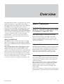
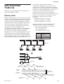
Overview
The DFW-SX910 with its 1/2-type PS IT CCD, and the
DFW-X710 with its 1/3-type PS IT CCD are highresolution industrial-use digital video camera modules.
The IEEE1394–1995 digital interface realizes a
transfer speed of 400 Mbps and outputs SXGA (1280
× 960)/YUV (4:2:2)/7.5 fps with the DFW-SX910,
XGA (1024 × 768)/YUV (4:2:2)/15 fps with the DFWX710. In addition, the DFW-SX910/X710 also adopts
a primary color filter CCD to realize good color
reproducibility, as well as a square pixel CCD to
eliminate the need for aspect ratio conversion in the
image processor.
What is the IEEE1394?
The IEEE1394 is the standard serial bus for sending
and receiving digital data. It is prescribed as “IEEE*
Std. 1394-1995 IEEE Standard for a High Performance
Serial Bus.”
The most outstanding feature of this interface is that it
realizes transfer speeds of up to 400 Mbps and can
handle large image data size. The interface is also
capable of “Isochronous transmission” which transmits
data real-time, for up to 64 channels. Connectors can
be inserted and disconnected while the unit is turned
on, and no terminators and no ID settings such as those
necessary for the SCSI interface are required.
* The Institute of Electrical and Electronics Engineers, Inc.
DFW-SX910/X710
Main Features
The DFW-SX910 video camera module
utilizes a 1/2-type PS IT CCD, and the DFWX710 utilizes a 1/3-type PS IT CCD
High-speed digital interface IEEE1394
The transmission speed is 400 Mbps. The DFWSX910 can output a digital image at 7.5 frames per
second; the DFW-X710 can output a digital image at
15 frames per second.
High-resolution
The DFW-SX910 (SXGA) has a high-resolution CCD
of 1.45 million pixels. The DFW-X710 (XGA) has a
high-resolution CCD of 800,000 pixels. Because the
CCDs are square pixel CCDs, you don’t need to
convert the aspect ratio in your image processing.
External trigger function
The external trigger shutter function allows the image
exposure to be coordinated with external equipment
and moving objects.
For exposure time, the unit is equipped with Trigger
Mode 0, which indicates the length of the exposure
using the shutter parameter, and Trigger Mode 1,
which controls exposure time by the width of the
trigger signal.
It is also able to utilize a software trigger initiated by a
command from a program running on a host computer.
3
Overview
Partial scan output image format
You can select and output any rectangle part from a
full-size image. This allows you to efficiently capture
images at a faster frame rate.
C-mount
Non-compressed YUV4:1:1/ YUV4:2:2/
Mono8 (8 bits each)
Solid aluminum diecast chassis
DFW-SX910/X710
4
Overview
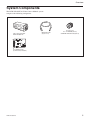
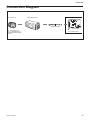
System Components
The DFW-SX910/X710 Video Camera Module system
comprises the following components.
Video Camera Module
DFW-SX910/X710
IEEE1394 Cable
(6-pin, 4.5 m)
C-mount Lens
J6 × 11 MACRO (Canon)
25MM HD LENS VF2509 (Canon)
Host Adapter Card
(Commercially available)
DFW-SX910/X710
5
Overview
Connection Diagram
C-mount Lens
DFW-SX910/X710
IEEE1394 Cable
Recommended Lens:
J6 × 11 MACRO (Canon)
25MM HD LENS VF2509
(Canon)
DFW-SX910/X710
Host Adapter Card
Host Equipment (PC, etc.)
6
Overview
Location of Parts and Operation
Front/Top/Bottom
Rear Panel
2
1
5
3
6
4
2
1
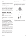
1 Lens mount (C-mount)
Attach any C-mount lens or other optical equipment.
Note
The lens must not project more than 7 mm (9/32 inch)
from the lens mount.
1 Lens mount face 2 7 mm (9/32 inch) or less
2 Flange back hole
Adjust the flange back by adjusting the screw at the
bottom of this hole.
5 TRIG IN/Exposure OUT connector
Connect the trigger signal generator (trigger output
connector) to this connector.
When trigger is OFF, or software trigger is ON, a
signal that indicates the exposure time is output from
pin 1 of the camera.
For details on the exposure out, see “Exposure Out”
(page 14).
6 CAMERA connector
Connect the IEEE1394 camera cable (supplied) to this
connector.
3 Pilot lamp
This lamp indicates the camera module operation
states:
OFF: Camera power OFF
Green: Camera power ON/Video signal output OFF
Orange: Camera power ON/Video signal output ON
4 Tripod hole
Install a tripod into this hole.
DFW-SX910/X710
7
Functions
Functions
IIDC Standard Features
Following features are defined by the IIDC standard,
v1.30. Only the Trigger feature is defined by the IIDC
standard, v1.31.
Brightness
This feature makes fine adjustment of the black level
possible.
Auto Exposure
This feature automatically adjusts the gain and shutter
settings, based on the brightness of the subject. To use
this feature, set the camera features and the video
format/mode as follows. This feature may not function
properly in any other settings.
Standard settings
DFW-SX910
DFW-X710
Video Format: 2
Video Mode: 0
Frame Rate: 7.5 fps
Trigger: OFF
Video Format: 1
Video Mode: 3
Frame Rate: 15 fps
Trigger: OFF
White Balance
This feature adjusts the color balance of the camera to
ensure that a white subject appears white in the video
image. Both manual and automatic settings are
available.
There are two automatic white balance modes; Auto
White Balance and One Push White Balance.
In the Auto White Balance mode, the camera senses
any change in lighting and automatically adjusts White
Balance accordingly. In the One Push White Balance
mode, the White Balance is adjusted automatically
once and fixed until you perform the adjustment again.
The camera’s internal circuits integrate the image data
within a defined area, using an algorithm that
approximates the average value to white. Because of
this algorithm, depending on the lighting environment,
a white subject may appear other than white in the
Auto White Balance mode.
We recommend that you shoot a white subject so that
white fills the entire screen in the specified lighting
environment and then perform the One Push White
Balance adjustment. When the calculation is
completed, the White Balance in this lighting
environment is adjusted.
The range of operation of each mode is as follows.
Manual : 2400 to 10000 K or more
Auto/One Push Auto: 2400 to 10000 K or more
Additionally, the camera employs a feature which can
change the reference point of the White Balance. For
details, see “PAINT” on page 14.
Sharpness
Hue
The picture can be adjusted using eight levels of
sharpness.
This feature adjusts color tones.
Saturation
This feature adjusts color intensity.
DFW-SX910/X710
8
Functions
Gamma
Setting examples
3 (003h) :
32 (020h) :
100 (064h) :
1000 (3E8h) :
1010 (3F2h) :
1150 (47Eh) :
Used for setting gamma compensation to OFF, ON (1),
or ON (2).
OFF : Outputs CCD signals for image processing
linearly.
ON (1) : For obtaining natural gradation taking into
account the characteristics of the monitor.
ON (2) : For obtaining three-dimensional images with
a subject that has a small luminance dynamic
range.
14 µs (1/100000)
1.005 ms (1/1000)
10.005 ms (1/100)
1s
2s
16 s
16 s
Gamma ON (2)
2
Output
Gamma ON (1)
Gamma OFF
1s
1
10 µs
Input
Concept of Gamma Characteristics
3
1000
1150
Shutter
For details on Auto Exposure, see page 8.
This feature sets exposure time. Both manual and
automatic settings are available.
When the automatic setting is selected, Shutter is
adjusted automatically, based on the brightness of the
subject.
At this time, the reference level (target point) of the
brightness is set in the Auto Exposure register.
With manual setting, the camera uses relative control
values indicated by a 12-bit integer and absolute
control values indicated using a 32-bit floating point
number.
For long exposure times
Relative control values for Shutter
The relationship between the parameter and the
exposure time is given by the following formulas.
Where
When exposure times longer than the currently set
frame rate cycle are set, the camera enters the long
exposure time mode, and the actual frame rate is
slowed in accordance with the exposure time.
Absolute control values for Shutter
Control of exposure time using absolute values is
possible. The values are indicated using a 32-bit
floating point value. (Unit: sec.)
The control steps are synchronized with the pixel
clock, and as the pixel clock is 15.25 MHz, one step is
approximately 65.6 ns.
The range for these values extends from
10 microseconds to 17.5 seconds.
Programming example;
union {
P = Parameter (003h ~ 47Eh)
E = Exposure time (s)
P >= 3 ~ P <= 1000
E=
P2
1000000
+ 0.000005
P > 1000 ~ P <= 1150
E = (P – 1000)*0.1 + 1.000005
DWORD
dwValue;
float
fValue;
} AbsoluteShutterValue;
1
// 1394 is expressed in quadlets,
// exposure time is indicated in seconds.
AbsoluteShutterValue.fValue = Exposure time;
WriteQuad(AbsoluteShutterOffsetAddress,
AbsoluteShutterValue.dwValue);
2
WriteQuad is a virtual function used to write in the
1394 register.
DFW-SX910/X710
9
Functions
AbsoluteShutterOffsetAddress is an offset address for
the absolute value control. See page 26 for the formula
for the offset address.
The change in shutter time will be used when the next
exposure starts. The current exposure will complete
with the previous shutter setting. This is true for all
exposure; short or long. If you intend to reflect the
new setting immediately, stop the output and start it
again.
Gain
This feature adjusts the brightness of the picture. Both
manual and automatic settings are available. The
variable range extends from 0 to 18 dB.
When automatic setting is selected, Gain is adjusted
automatically, based on the brightness of the subject.
At this time, the reference level (target point) of the
brightness is set in the Auto Exposure register.
For details on Auto Exposure, see page 8.
70 to 511
512 to 551
Gain = 20log10([658+code]/[658–code])– 0.35
Gain =(0.0354)(code)– 0.35
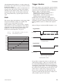
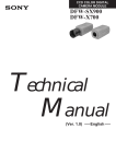
Trigger Shutter
This feature allows you to control the exposure timing
via a external signal input (Hardware Trigger) or via a
command sent from application software (Software
Trigger). There are two trigger modes:
– Trigger Mode 0 where the exposure time is
controlled by the shutter parameter
– Trigger Mode 1 where the exposure time is
controlled by the trigger pulse width.
In both modes, the leading edge of the hardware
trigger starts the exposure. In Trigger Mode 0, the
maximum exposure is limited by the shutter parameter.
In Trigger Mode 1, there is no limit to the exposure
time.
Software Trigger is defined by IIDC Standard, v1.31.
Trigger Mode 0
Input signal
4.0 to 5.0 Vp-p
Trigger width: 10 µs or wider
20.00
18.00
Exposure time
16.00
14.00
Set the exposure time using
the Shutter feature.
12.00
10.00
Trigger Mode 1
8.00
6.00
Input signal
4.00
2.00
0.00
0
100
200
300
400
500
600
Exposure time
Set the exposure time using the
width of the trigger signal pulse.
• Input impedance: 10 kΩ
It is possible to trigger the cameras at full frame rate
using hardware trigger. (This was not possible with
the earlier DFW-SX900/X700 because the trigger in
would not be accepted until after the previous images
was output from the camera.) It is very important that
the exposure not end before the previous image is out
of the cameras. If the camera is trigger too fast or
there is noise on the trigger line that will cause the
exposure to end before previous image is output, you
will get double exposure of the image.
DFW-SX910/X710
10
Functions
Pan/Tilt
Pan/Tilt is a feature to move a region of interest (ROI)
image (smaller than the full image) vertically and
horizontally about the full image of the camera. When
the ROI image is defined (use the video mode setup),
the ROI is centered in the full image.
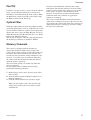
Optical Filter
Normally, Optical Filter is the feature which switches
electronic optical filters, such as an ND filter or a color
conversion filter. However, on this camera, the feature
chooses the preset values of White Balance. If 0 is set,
White Balance for 3200 K is utilized. If 1 is set, White
Balance for 5600 K is utilized.
This feature is effective when the color temperature of
the shooting environment is 3200 K or 5600 K.
Using the CameraInitialize command, the setting
information stored in the channels is cleared and the
camera features and the video mode are reset to their
initial values. To preserve the information in the
channels, be sure not to send the CameraInitialize
command while driver software or application
software is starting up.
The value saved for Pan/Tilt is initialized when the
video mode is changed. To preserve the value, be sure
not to change the video mode while driver software or
application software is starting up, or before sending
the video start command.
Memory Channels
The camera is equipped with two channels of
nonvolatile memory to hold camera settings. The
settings of all camera features and the video mode can
be stored. The camera memorizes the channel most
recently used to read out the setting information, and
retains it, even if the power is turned off. Therefore,
the camera loads the information from that channel
when the power is turned on.
The video mode settings are loaded only when the
power is turned on.
To start up the camera with the desired setting,
perform the following procedure.
1 Make changes to the camera features or the video
mode settings.
2 Store the current setting in Memory Channel 1 or
Memory Channel 2.
3 Load the information that was stored in step 2.
When you start up the camera the next time, the
settings that you have just made will be loaded
automatically.
DFW-SX910/X710
11
Functions
Partial Scan
The Partial Scan feature for outputting a small part of
the full image called a Region of Interest (ROI). The
ROI can be defined as any single contiguous rectangle
that can be drawn on an even 16×16 grid of the whole
image. The Unit Cell is the smallest region of interest
that can be defined as is one of the rectangles on the
even 16×16 grid.
DFW-SX910 unit cell = 80×60 pixels
DFW-X710 unit cell = 64×48 pixels
Vertical (Vertical Direction)
Cutting by Partial Scan mode
Horizontal (Horizontal Direction)
The frame rate of the camera can be increased by
reducing the number of vertical lines output. In Partial
Scan mode, the frame rate is determined by the
exposure/shutter time plus the time to transmit the
image. In free run mode, the exposure starts after the
last image is transmitted. In triggered mode, the
exposure can be overlapped with the image output but
care must be taken to ensure that the exposure end
does not occur before the ouput of the previous image.
To use the Partial Scan feature, set Format7, Mode0.
In Partial Scan mode, you can select from among
Mono8, YUV4:1:1, and YUV4:2:2 as the color coding.
DFW-SX910/X710
12
Functions
IIDC Extended
Features
Following are vender-unique features, which are not
defined by the IIDC standard.
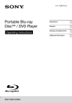
Memory Shot
Memory Shot allows the camera to collect one or more
images into on-board image memory without tying up
available 1394 bus bandwidth. Normally, a 1394 IIDC
camera transmits a new image immediately after the
acquisition so the 1394 bus bandwidth is pre-allocated
to the camera to ensure deterministic performance.
1394 bus bandwidth is allocated based on resolution
and frame rate assigned. Multiple camera
configurations frequently demand more bandwidth (or
more ISO channels) than available on a single 1394
bus. The user can either reduce the bandwidth
required by each cameras by reducing the frame rate or
resolution or increase available bandwidth by adding
more 1394 busses on one or more computers. Memory
Shot offers another alternative to managing the 1394
bus bandwidth in multiple camera configurations. This
is especially useful in hardware triggered
environments. Multiple cameras can be setup to
acquire one or more images simultaneously without
consuming any 1394 bus bandwidth. The applications
software can setup the multiple cameras on a single
1394 bus on one computer for Memory Shot
acquisition, query the camera to verify that the
image(s) are in the camera on-board memory, and tell
each camera to transmit its stored image(s). These
cameras have 128 Mbit of frame memory.
It can hold:
1280×960 at YUV4:2:2 is 6 images
1280×960 at YUV4:1:1 is 9 images
1280×960 at MONO8 is 13 images
The number of images (N) that can be holded is
defined by the image size and color coding.
N = 16 * 1024 * 1024 (byte) / ( W * H * K )
W: image width (pixels)
H: image hight (pixels)
K: coefficient of color coding
K
color coding
1
Mono8/Raw8
1.5
YUV4:1:1
2
YUV4:2:2
Trigger input
1394
1394
1394
1394
Conventional system
1394
Power repeater
Trigger input
Images input
from CCD
Acquisition
phase
Transmission
phase
image 1
image 2
image 3
128 Mbit
frame memory
image 1
image 2
image 3
You can specify the timing of the
transmission of the stored images.
Images output to
1394 bus
DFW-SX910/X710
13
Functions
PAINT
This feature enables you to shift the reference point of
the White Balance. If you change the parameter of this
feature, the white-balance adjustment references to a
color other than white.
User Memory Area
Exposure Out
A signal that indicates an exposure time is output from
pin 1 on the 4-pin connector on the rear panel.
When the hardware trigger feature is used, the signal
above is not output. The output is the open-corrector
type.
NC
The camera is equipped with 256 bytes of nonvolatile
memory to hold information you need.
The information is read or written by quadlet. Both
Quadlet Read/Write and Block Read/Write
transactions are available. The information will be
preserved even if the power to the camera is turned off.
Exposure out
4
1
3
2
Trigger input
Non-IIDC Features
GND
+5 V
The following features are not defined by the IIDC
standard.
1 kΩ
1394 Bus Synchronization
Cameras connected to the same bus are automatically
synchronized. Specifically, the start of exposure will
be the same for all cameras running at the same frame
rate.
The DFW-SX910/X710 series and XCD-SX910/X710
series cameras uses the same automatic bus
synchronization system. The 1394 bus is a shared
resource with finite bandwidth. The number of
cameras that can be simultaneously is limited by the
ISO bandwidth available (~32 MBytes/sec) and ISO
channels (4-8 depending on your computer 1394
interface). Bandwidth is allocated based on the
resolution and frame rate selected for the camera. To
reduce the bandwidth for a camera, reduce the output
image size and/or the frame rate.
For instance, if a camera is to transmit 1280×960 in
YUV4:2:2 at 7.5 fps, approximately 18.4 MBytes/sec;
more than half the available bandwidth. Reducing the
frame rate to 3.75 fps reduces the bandwidth to
approximately 9.2 MBytes/sec allowing 3 cameras to
transmit simultaneously.
Exposure
time
The LOW period that is given by an output wave form
is an approximate guideline. It does not correspond
exactly to the actual exposure time.
CPU operation timing can cause jitter in the 1394 bus
synchronization of approximately 4 microseconds.
External hardware (trigger) synchronization can be
used to ensure further accuracy. To synchronize
cameras on different 1394 busses, use a common
hardware trigger to all the cameras.
DFW-SX910/X710
14
Control
Control
Camera Command
Status Register
This camera complies with the IIDC 1394-based
Digital Camera Specification, version 1.30 (hereinafter
referred to as IIDC v1.30).
The standards document can be purchased from
1394TA (the 1394 Trade Association). Because it is
very helpful in understanding the explanations in this
Technical Manual, we recommend that you purchase a
copy of IIDC v1.30.
The remaining 28 bits can be allocated to the camera
as addresses, but in reality, the first 4 bits are fixed at
0, so the largest number of bits that can be allocated to
the camera as address space is 24 bits.
The bus and node IDs may be changed if the topology
is restructured because of bus reset, so only the least
significant 32 address bits are shown in this Technical
Manual.
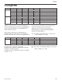
Address
Register
F0000000
Base address
F0000400
ConfigROM area
F0F00000
Memory Map
1394 devices have a 64-bit address space. The upper
10 bits show the bus ID (0~1023), and the next six bits
show the node ID (0~63). The IIDC standard requires
the next 20 bits to be 1.
---BusID--- NodeID --------Must be 1--------
----Address used by the camera----
bbbbbbbb | bbnnnnnn | 11111111 | 11111111 | 11110000 | 11110000 | 00000000 | 00000000
DFW-SX910/X710
Base addresses for camera commands
F0F00000
CameraInitialize
F0F00100
Video Format Inq
F0F00180
Video Mode Inq
F0F00200
Frame Rate Inq
F0F002E0
Format7 CSR Inq
F0F00400
Basic Func Inq
F0F00500
Feature Element Inq
F0F00600
Isochronous Control register
F0F0071C
AbsoluteControlCSR Inq for Shutter
F0F00800
FeatureControl
F0F00970
AbsoluteControlCSR for Shutter
F0F10000
Format7Mode0 CSR
F0F30000
Access Control Register
F0F40000
Memory Shot control
F0F50000
User Memory
15
Control
ConfigROM
Offset
0-7
8-15
400h
04
1F
Info
404h
31
33
39
34
Block
408h
20
FF
60
00
40ch
08
00
46
02
NodeVendorID/ChipID-Hi
410h
00
0F
00
01
ChipID-Lo
ModuleVendorID
Bus
16-23
24-31
ROM CRC
Root
414h
Directory
418h
03
0004
08
00
CRC
46
41ch
0C
00
83
C0
420h
8D
00
00
02
IndirectOffset
424h
D1
00
00
04
UnitDirectoryOffset
With the exception of bits 8 to 15 of the 400h offset
address field, the length of the entire ConfigROM field
is made up of 1Fh Quadlets. So ConfigROM from
400h to 47Fh is 128 bytes.
previous models, this field has been retained in this
model, but in writing drivers and software
applications, be sure to ignore this field. For a
NodeUniqueID, use NodeVendorID/ChipID-Hi +
ChipID-Lo in BusInfoBlock.
Offset address 420h and key code 8Dh indicate a
NodeUniqueID Leaf offset, but in 1394a-2000, this
field has been eliminated. To ensure compatibility with
Offset
8-15
16-23
12
00
A0
2D
UnitSpecID
43Ch
13
00
01
02
UnitSoftwareVersion
440h
D4
00
00
01
UnitDependentDirectory Offset
Unit
434h
Directory
438h
0-7
0003
24-31
CRC
For offset address 434h, the length of the
UnitDirectory is 3 Quadlets. UnitSpecID (00A02Dh)
conforms to 1394TA standards.
UnitSoftwareVersion (000102h) conforms to the IIDC
standard, v 1.30.
DFW-SX910/X710
The offset address of UnitDirectory is required to be
424h +000004h * 4 = 434h
The offset address of UnitDependentInfo is required to
be
440h + 000001h * 4 = 444h
16
Control
Offset
0-7
8-15
16-23
0003
24-31
Unit
444h
CRC
Dependent
448h
40
3C
00
00
CommandRegsBase
Info
44ch
81
00
00
02
VendorNameLeaf
450h
82
00
00
05
ModelNameLeaf
For offset address 444h, the length of the
UnitDependentInfo is 3 Quadlets.
The offset address of VendorNameLeaf is required to
be
44Ch + 000002h * 4 = 454h
CommandRegsBase is the base address of the camera
control register.
F0000000h + 3c0000h * 4 = F0F00000h
The offset address of ModelNameLeaf is required to
be
450h + 000005h * 4 = 464h
VendorNameLeaf
Offset
0-7
8-15
16-23
0003
24-31
Vendor
454h
CRC
Name
448h
00
00
00
00
Leaf
44ch
00
00
00
00
450h
53
4F
4E
59
16-23
24-31
“SONY”
For offset address 454h, the length of the
VendorNameLeaf field is 3 Quadlets.
The subsequent 8 bytes are fixed at 00.
After that, the four characters for “SONY” are entered.
ModelNameLeaf
Offset
0-7
8-15
Model
464h
0006
CRC
Name
468h
00
00
00
00
Leaf
46ch
00
00
00
00
470h
44
46
57
2D
“DFW-”
474h
53
58
39
31
“SX91”
478h
30
20
76
31
“0 v1”
47Ch
2E
30
32
41
“.02A”
For offset address 464h, the length of the
ModelNameLeaf field is 6 Quadlets.
The subsequent 8 bytes are fixed at 00.
For the DFW-SX910, the 16 characters “DFW-SX910
v1.02A” come next. For the DFW-X710, the15
characters are “DFW-X710 v1.02A”.
Model names are subject to change with the upgrade of
firmware.
DFW-SX910/X710
17
Control
Control Base Address
Format7
Data
Address
Every register address is decided based on the base
address found in the CommandRegsBase field of
ConfigROM. F0F00000h is the control base address
on this camera.
Verifying Supported
Video Modes
F0F0019Ch
F0F00100h
DFW-SX910
DFW-X710
E1000000h
C1000000h
We find that the DFW-SX910 supports Format0/1/2/7, and
the DFW-X710 supports Format0/1/7.
Next, for each format, we will find out which video
modes are supported.
Format0
Data
Address
F0F00180h
DFW-SX910
DFW-X710
74000000h
74000000h
We find video modes 1, 2, 3, and 5 of Format0 are
supported.
Data
F0F00184h
80000000
Next, for each video mode, we will find out which
frame rates are supported.
Data
DFW-SX910
DFW-X710
F0F00204h
(Format0Mode1)
60000000h
70000000h
F0F00208h
60000000h
70000000h
F0F0020Ch
(Format0Mode3)
60000000h
70000000h
F0F00214h
(Format0Mode5)
60000000h
70000000h
F0F00220h
(Format1Mode0)
60000000h
70000000h
F0F00228h
(Format1Mode2)
20000000h
30000000h
F0F0022Ch
(Format1Mode3)
E0000000h
F0000000h
F0F00234h
(Format1Mode5)
E0000000h
F0000000h
F0F00240h
E0000000h
–
E0000000h
–
(Format2Mode0)
F0F00248h
(Format2Mode2)
Based on the data above, the formats, modes, and
frame rates supported are shown in the tables on the
next page.
Format1
Address
C0000000h
(Format0Mode2)
Data
Address
DFW-X710
We find that the DFW-SX910 supports video modes 0 and 1
of Format7, and the DFW-X710 supports video mode 0 of
Format7.
Address
First, we will find out what video formats are
supported.
DFW-SX910
DFW-SX910
DFW-X710
B4000000h
B4000000h
We find video modes 0, 2, 3 and 5 of Format1 are
supported.
Format2 (DFW-SX910 only)
Data
Address
DFW-SX910
DFW-X710
F0F00188h
A0000000h
–
We find video modes 0 and 2 of Format2 are supported.
DFW-SX910/X710
18
Control
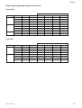
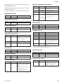
Video modes supported (except for Format7)
DFW-SX910
Frame Rate
Format
0
Mode
Image Size
Color Coding
15
7.5
3.75
1.875
1
320 × 240
YUV4:2:2
a
a
–
2
640 × 480
YUV4:1:1
a
a
–
3
640 × 480
YUV4:2:2
a
a
–
5
640 × 480
Mono8
a
a
–
0
800 × 600
YUV4:2:2
a
a
–
2
800 × 600
Mono8
a
–
–
3
1024 × 768
YUV4:2:2
a
a
a
5
1024 × 768
Mono8
a
a
a
0
1280 × 960
YUV4:2:2
a
a
a
2
1280 × 960
Mono8
a
a
a
Format
Mode
Image Size
Color Coding
15
7.5
3.75
1.875
0
1
320 × 240
YUV4:2:2
a
a
a
–
2
640 × 480
YUV4:1:1
a
a
a
–
3
640 × 480
YUV4:2:2
a
a
a
–
5
640 × 480
Mono8
a
a
a
–
0
800 × 600
YUV4:2:2
a
a
a
–
1
2
DFW-X710
Frame Rate
1
DFW-SX910/X710
2
800 × 600
Mono8
a
a
–
–
3
1024 × 768
YUV4:2:2
a
a
a
a
5
1024 × 768
Mono8
a
a
a
a
19
Control
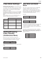
Video Mode Settings
Select the video mode you want to use from the tables,
and make the required settings.
As examples, the register settings for Format2, Mode0,
and a frame rate of 7.5 fps for the DFW-SX910, and
Format1, Mode3, and a frame rate of 15 fps for the
DFW-X710, are shown.
In addition, an isochronous transfer speed of 400 Mbps
and isochronous channel 0 are used in these examples.
Normally, set the isochronous transfer speed to 400
Mbps.
When multiple cameras are used simultaneously, set
different isochronous channels for each one.
One Shot and Multi
Shot
This camera supports both One Shot and Multi Shot
commands. With a One Shot command, after
outputting just one single-frame image, the camera
enters an “idling” state. With a Multi Shot command,
the camera enters the “idling” state after outputting
exactly the specified number of images.
One Shot
Address
Data
F0F0061Ch
80000000h
Data
Address
F0F00600h
(Frame Rate)
F0F00604h
DFW-SX910
DFW-X710
40000000h
60000000h
00000000h
60000000h
F0F00608h
(Video Format)
40000000h
20000000h
F0F0060ch
(IsoChannel/
IsoSpeed)
02000000h
02000000h
Multi Shot
Address
Data
F0F0061Ch
4000nnnnh
(Video Mode)
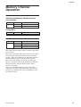
Starting/Stopping
Video Transfer
(Continuous Shot)
nnnn indicates the number of frames to be output. You
can specify any number between 0001h ~ FFFFh
(1~65535). If 0000h is specified, you can think of it as
1 being set instead.
Execution of Continuous Shot, One Shot, and Multi
Shot are prioritized as follows. When a command with
higher priority is being executed, one with a lower
priority is ignored.
Priority
Command
1
Continuous Shot
2
One Shot
3
Multi Shot
In the device driver, after the preparations for
receiving isochronous data are made, video transfer
starts when the following commands are issued.
Address
F0F00614h
Data
80000000h
When the following command is issued, video transfer
stops.
Address
F0F00614h
DFW-SX910/X710
Data
00000000h
20
Control
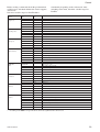
Memory Channel
Operation
Save
Selecting the Memory Channel used to
save the data
Address
F0F00620h
Data
Operation
10000000h
Selects Ch 1.
20000000h
Selects Ch 2.
Saving data
Address
F0F00618h
Data
Operation
80000000h
Saves the current setting.
Data
Operation
00000000h
Loads the default settings.
10000000h
Loads the setting information in Ch 1.
20000000h
Loads the setting information in Ch 2.
Load
Address
F0F00624h
The settings of the camera features and the video mode
can be stored.
The camera memorizes the channel most recently used
to read out the setting information using nonvolatile
memory. Then, the information in that channel will be
loaded when the power is turned on the next time.
The video mode settings are loaded only when the
power is turned on. If you read out Memory Channels
during operation, only the settings of the camera
features are loaded.
The value of Pan/Tilt depends on the video mode
settings. If you change the video mode after carrying
out the Save command, the value of Pan/Tilt may not
be loaded correctly.
DFW-SX910/X710
21
Control
Feature Controls (Complies with the IIDC
Standard)
This camera supports the following features.
Brightness
Makes fine adjustment of the black level possible.
Auto Exposure
Controls the target video level value when Shutter/Gain is set to Auto.
Sharpness
Adjusts the picture sharpness.
White Balance
Adjusts the color balance of the camera to ensure that a white subject appears white in the video image.
Hue
Adjusts color tones.
Saturation
Adjusts color intensity.
Gamma
Sets a gamma curve.
Shutter
Controls the exposure time. To control this feature, you can use both relative control values from 1/100,000 of a second to 16
seconds, allocated from 3 to 1150, and absolute value control, with values from 1/100,000 of a second to 17.5 seconds, set
continuously.
Gain
Controls the gain in the range from 0 dB to 18 dB. The unit of the adjustment is approximately 0.035 dB.
Trigger
Controls external triggers. This feature supports Trigger Mode 0 and 1. A software trigger feature is also supported.
Pan/Tilt
Sets CCD output range (both horizontal (Pan) and vertical (Tilt)). The video mode predetermines the variable range. Not
available in Partial Scan mode (Format7/Mode0).
Optical Filter
Sets a preset value for White Balance. Setting values of 3200 K and 5600 K are available.
DFW-SX910/X710
22
Control
Before sending a command, check the predetermined
variable range and check whether the feature supports
Auto mode.
Note that variable ranges for Pan/Tilt differ
Address
Data
F0F00500h
8900007Fh
(Brightness)
F0F00504h
8905A073h
(Auto Exposure)
F0F00508h
89000007h
(Sharpness)
F0F0050Ch
9B700900h
(White Balance)
F0F00510h
890530ADh
(Hue)
F0F00514h
890001FFh
(Saturation)
F0F00518h
89080082h
(Gamma)
F0F0051Ch
(Shutter)
CB00347Eh
considerably depending on the video mode. After
switching video mode, check the variable range for
Pan/Tilt.
Bit*1)
0
This feature exists.
4
The value can be read out.
7
Manual setting can be selected.
8-19
Min. 0
20-31
Max. 127
0
This feature exists.
4
The value can be read out.
7
Manual setting can be selected.
8-19
Min. 90
20-31
Max. 115
0
This feature exists.
4
The value can be read out.
7
Manual setting can be selected.
8-19
Min. 0
20-31
Max. 7
0
This feature exists.
3
One Push Auto mode can be selected.
4
The value can be read out.
6
Auto setting can be selected.
7
Manual setting can be selected.
8-19
Min. 1792
20-31
Max. 2304
0
This feature exists.
4
The value can be read out.
7
Manual setting can be selected.
8-19
Min. 83
20-31
Max. 173
0
This feature exists.
4
The value can be read out.
7
Manual setting can be selected.
8-19
Min. 0
20-31
Max. 511
0
This feature exists.
4
The value can be read out.
7
Manual setting can be selected.
8-19
Min. 128
20-31
Max. 130
0
This feature exists.
1
Absolute value control possible
4
The value can be read out.
6
Auto setting can be selected.
7
Manual setting can be selected.
8-19
Min. 3
20-31
Max. 1150
*1) According to the IEEE 1394 specifications, the most significant bit is shown as 0.
DFW-SX910/X710
23
Control
Address
Data
F0F00520h
8B046227h
(Gain)
F0F00530h
8C81C000h
(Trigger)
Bit*1)
0
This feature exists.
4
The value can be read out.
6
Auto setting can be selected.
7
Manual setting can be selected.
8-19
Min. 70
20-31
Max. 551
0
This feature exists.
4
The value can be read out.
5
This feature can be switched ON and OFF.
8
Trigger Source0 exists.*2)
15
Software Trigger Mode exists.*2)
16
Trigger Mode0 exists.
17
Trigger Mode1 exists.
0
This feature exists.
(Pan)
4
The value can be read out.
F0F00584h
7
Manual setting can be selected.
(Tilt)
8-19
Min. (Depends on the video mode.)
20-31
Max. (Depends on the video mode.)
0
This feature exists.
4
The value can be read out.
7
Manual setting can be selected.
8-19
Min. 0
20-31
Max. 1
F0F00584h
F0F0058Ch
(Optical Filter)
89******
89000001h
*1) According to the IEEE 1394 specifications, the most significant bit is shown as 0.
*2) These features comply with IIDC v1.31.
DFW-SX910/X710
24
Control
Actual control can be carried out by setting registers
from F0F00800 onward.
ddd indicates the control value expressed as a 12 bit
hexadecimal number.
xxx indicates that any setting made will be ignored.
Shutter (exposure time) control
Address
F0F0081C
Data
82000ddd
83000xxx
Sets Shutter to AUTO.
C2000xxx
Controls shutter using the absolute
control value.
Brightness control
F0F00970
Address
F0F00800
Data
82000ddd
(See page 26.)
Adjusts the black level.
AE reference control
Address
F0F00804
Data
82000ddd
Sets the AE reference value.
F0F00808
F0F00820
Data
82000ddd
Adjusts the picture sharpness.
0 (Soft)y7 (Sharp)
White Balance control
F0F0080C
Address
Data
82uuuvvv
Adjusts White Balance using relative
values.
uuu: Blue component
vvv: Red component
83xxxxxx
Sets Auto White Balance.
86xxxxxx
Adjusts White Balance automatically
once, then the feature turns to manual
mode.
F0F00810
Data
82000ddd
F0F0062C*
83000xxx
Sets Gain to AUTO.
Data
82000000
Sets Hardware Trigger Mode0.
82010000
Sets Hardware Trigger Mode1.
82E00000
Sets Software Trigger Mode0. *
82E10000
Sets Software Trigger Mode1. *
80000000
Outputs a software trigger.
In Trigger Mode0, automatically reset
to 0 when exposure ends.
00000000
In Trigger Mode1, ends exposure if
“0” is set.
Pan/Tilt control
Address
F0F00814
Sets Gain manually.
Adjusts color tones.
Saturation control
Address
Data
82000ddd
* These features comply with IIDC v1.31.
Hue control
Address
After F0F0081C has been set to
Absolute value control, set exposure
time using this register.
Trigger control
F0F00830
Address
Indicates an
arbitrary value
using a 32-bit
floating point
number.
Gain control
Address
Sharpness control
Address
Controls shutter using the manually
set relative value.
Data
82000ddd
Data
F0F00884
82000ddd
Sets Pan manually.
F0F00888
82000ddd
Sets Tilt manually.
Adjusts color intensity.
Optical Filter control
Gamma control
Address
F0F00818
DFW-SX910/X710
Address
Data
82000ddd
F0F0088C
Sets the gamma compensation.
82000080: Deactivates the gamma
feature.
82000081: Activates the gamma
feature (gamma curve 1).
82000082: Activates the gamma
feature (gamma curve 2).
Data
82000ddd
Sets preset value for White Balance.
82000000: value for 3200 K
82000001: value for 5600 K
25
Control
The formula for the absolute value shutter
control register address
Absolute value shutter control CSR offset
address
Address
F0F0071C
Data
003C025C
Absolute value shutter control CSR
offset
The register address for absolute value shutter control
is given by the following formula.
F0000000h + 003C025Ch * 4 = F0F00970h
DFW-SX910/X710
26
Control
Feature Controls (IIDC Extended)
This camera supports the following extended features.
PAINT
Sets the reference point of the White Balance to other than white.
Memory Shot
Stores an image on the frame memory and outputs it asynchronously.
User Memory
A 256-byte memory area reserved for users. The information in this area will be preserved even if the power to the camera is
turned off.
To control these extended features (Vendor Unique Features), use the Access Control Register defined by the
IIDC standard.
The formula for the ACR offset address
First, we will find out whether the camera supports Vender Unique Features.
F0F00400h
80001802h
(BASIC_FUNC_INQ)
F0F00480h
(Advanced_Feature_Inq)
003CC000h
0
Vender Unique Features are supported.
19
One Shot can be transmitted.
20
Multi Shot can be transmitted.
28-31
2: Memory channel 2
ACR offset
The Access Control Register address is given by the
following formula.
F0000000h + 003CC000h * 4 = F0F30000h
DFW-SX910/X710
27
Control
PAINT Control
Issue the following commands using BlockWrite or
QuadletWrite.
F0F30000h
F0F30004h
F0F30008h
<= 08004600h
<= 0002FFFFh
<= UUUUVVVVh
Specify UUUU and VVVV within the range from –4
to +4 using 16-bit signed integers.
The values which you set will be preserved even if the
power to the camera is turned off. To restore the initial
value, set UUUU and VVVV to 0.
Memory Shot Control
The following instructions are provided to allow you
to operate the camera in the external synchronization
mode.
1 Stop the video transmission.
2 Set camera features, such as video mode, frame
rate, etc.
If you change the image size to a smaller one, a
higher frame rate will be available.
3 Issue the following commands using BlockWrite or
QuadletWrite.
F0F30000h
F0F30004h
F0F30008h
<= 08004600h
<= 0010FFFFh
<= 80000000h
Then, the Memory Shot feature is activated.
4 Set the external trigger feature to ON.
F0F00830h
<= 82000000h
8 If output ends, issue the video stop command.
This step cannot be skipped.
One procedure is completed. You can perform the
operation from step 4 over again.
To exit from the Memory Shot mode and
return to the normal mode
Issue the following commands using BlockWrite or
QuadletWrite.
F0F30000h
F0F30004h
F0F30008h
<= 08004600h
<= 0010FFFFh
<= 00000000h
If you perform the procedure with a camera of
which the external Trigger Mode is set to OFF
Capturing starts at the moment you issue the command
in step 5.
User Memory Control
Issue the following commands using BlockWrite or
QuadletWrite.
F0F30000h
F0F30004h
F0F30008h
<= 08004600h
<= 0011FFFFh
<= 80000000h
The user memory area is opened. User Memory is
mapped to F0F50000h-F0F500FFh.
QuadletRead/Write and BlockRead/Write are
available.
If you issue the following commands using
BlockWrite or QuadletWrite, the user memory area is
locked and will be inaccessible.
F0F30000h
F0F30004h
F0F30008h
<= 08004600h
<= 0011FFFFh
<= 00000000h
5 Issue the start capturing command.
F0F40000h
<= 0100nnnnh
nnnn indicates the number of frames to be
captured. When the specified number of frames is
captured or the memory fills up with data, the
capture mode will be released. To find the number
of the frames captured, read out F0F40000h. The
end flag shows that the capture mode has been
released.
0101000Ah
When the mode is released after 10 frames are
captured, bit 16 indicates an end flag.
6 Set the external trigger feature to OFF.
F0F00830h
<= 80000000h
7 Issue the video start command.
The camera outputs the frames in the memory area
and then enters the “idling” state. The frames are
output sequentially in the captured order. You
cannot specify a frame to be output on a random
basis.
DFW-SX910/X710
Notes on ACR access
The Access Control Register is managed by the timeout control. A series of commands must be completed
within a time-out duration. The time-out duration is
specified using the ACR access commands.
F0F30000h <= 08004600h
Access control key (32-bit)
F0F30004h <= 0011FFFFh
Access control key (16-bit) +
‘F’ + time-out (12-bit)
F0F30008h <= 80000000h
Control commands
Time-out duration is specified using 12-bit values, and
the unit is 1 ms. FFF indicates 4095 ms.
28
Control
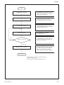
Partial Scan Operations
Partial scan can be set using either the SettingBit or
IIDC v1.20 interchange.
An example of the setting procedure (In the case of a
DFW-SX910)
1280
240
320
960
480
When shooting the center of the whole
screen with a screen size of 640 ×
480, and with color coding set to
YUV4:2:2, the packet size set to
maximum in order to capture the
image at the highest speed.
640
Start
Set the format.
Write E0000000h in F0F00608h.
(Set the format to 7.)
Check available modes.
Read F0F0019Ch. C0000000h is
returned, showing Mode0 and Mode1 are
available.
Set the mode.
Write 00000000h in F0F00604h.
(Set the Mode to 0.)
Obtain a CSR offset address.
Read F0F002E0h. 003C4000h is
returned, showing the offset address for
Mode0 is F0F10000h. (F0000000h
+4*003C4000h)
Go to Step 2.
DFW-SX910/X710
29
Control
Step 2
MaxSize is read out.
Read F0F10000. 050003C0h is returned,
showing the maximum image size is 1280
× 960.
UnitSize is read out.
Read F0F10004h. 0050003Ch is
returned, showing the unit size is 80 × 60.
Therefore, the screen can be divided into
256 sections (16 × 16, vertically and
horizontally.)
ColorCoding is read out.
Read F0F10014h. E0000000h is
returned, showing Mono8, YUV4:1:1, and
YUV4:2:2 are available.
Set the image position.
Write 018000F0h in F0F10008h.
(Horizontal position = 320, Vertical
position = 240)
Set the image size.
Write 028001E0h in F0F1000Ch.
(Width = 640, Height = 480)
Set the color coding ID.
Write 02000000h in F0F10010h.
(YUV4:2:2 = 2)
Set the SettingBit.
Write C0000000h in F0F1007Ch.
Wait until the SettingBit falls.
Error
Check ErrorFlag 1.
Read F0F1007Ch. Wait until Bit 1 falls.
Read F0F1007Ch. Check that Bit 8 is not
set. If an error occurs, the setting was
wrong. Try other settings.
No error
Go to Step 3.
DFW-SX910/X710
When using IIDC v1.20, skip the
procedures described within the broken
line.
30
Control
Step 3
PixelNumber is read out.
Read F0F10034h. The number of pixels is
obtained. (Use this information if required
by the software application.)
TotalByte is read out.
Read F0F10038-3Ch. Total number of
bytes (of the effective image) is obtained.
PacketParaINQ is read out.
Sets the packet size.
Read F0F10040h. Packet size that can be
set is obtained. (640 (minimum) and 1280
(maximum) for this camera.)
Write 02800000h in F0F10044h.
(PacketSize = 1280)
Error
Read F0F1007Ch. Check that Bit 9 is not
set. If an error occurs, the PacketSize was
wrong. Try other settings.
Check the packet size.
No error
Obtain the number of packets.
Read F0F10048h. The number of packets
per 1 frame is obtained. (The total number
of bytes of data output by the camera:
output = packet size × number of packets)
Setting completed.
Image transmission is now ready. Send a video start
command to output images.
The camera does not support RecBytePerPacket.
DFW-SX910/X710
31
Appendix
Appendix
Notes on the Camera
Operations
1. If a Frame rate decrease.
Frame rate may decrease depending on your shutter
settings.
a. When a series of images is output, the instant
when the exposure time is shorter than one
frame, and the exposure time setting is shortened
using the shutter.
Exposure
time
A
A
B
B
B
C
TRIG
(However, partial activation can be used if the
following conditions are exceeded. Refer to the table
on pages 37 and 38.)
T
T
Mode 0: timing after the exposure set by the parameter
is finished
Mode 1: at the trailing edge of the trigger pulse
DFW-SX910 : T≥1/15 sec
DFW-X710 : T≥1/30 sec
3. When AE (Auto Exposure) is not available
The camera loads the AE function that controls Gain
and Shutter automatically. However, the function
works properly in the following standard settings only.
DATA
A>B
B<C
In this case, the camera tends to skip 1 frame
image, resulting in a decrease in the frame rate.
Keep this in mind when using an application that
switches exposure time frequently.
b. With a long exposure
In long exposure mode, the exposure time is set
longer than the image transmission cycle. In this
case, frame rate decreases according to the
exposure time.
2. When using Trigger Mode
When this camera is set to accept a trigger at the
fastest possible timing, it can accept overlap of the
next trigger signal in the midst of video transmission.
For this reason, a trigger inhibition period is not
available. Thus, if a trigger signal is input before the
CCD can change to the state where it can accept
exposures, multiple exposures can occur, and it cannot
capture the correct image. Make sure that the
following conditions are met when the trigger is
activated.
DFW-SX910/X710
Standard settings
DFW-SX910 Video Format: 2
Video Mode: 0
Frame Rate: 7.5 fps
Trigger: OFF
DFW-X710
Video Format: 1
Video Mode: 3
Frame Rate: 15 fps
Trigger: OFF
When other modes are set, activating the AE function
is possible, however, normal operation of the function
is not guaranteed.
In Trigger Mode—AE works properly when the video
format is set to the standard setting and the trigger
cycle is set to the same as that of the video format.
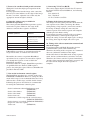
4. Auto shutter control and absolute value shutter
control
The auto shutter control function cannot be used in the
Absolute value control mode. When Shutter is set to
Auto, the Absolute value control mode is
automatically canceled.
32
Appendix
5. Issues to be considered with partial activation
With partial activation, high-speed operation of the
CCD occurs.
If strong light comes into the image at the same time,
there may be some influence at the edges of the image.
In such a case then, adjust the lens so that only the
appropriate amount of light is allowed.
8. Converting Y/Cr/Cb to R/G/B
The camera outputs digital Y/Cr/Cb data. To convert
the digital Y/Cr/Cb data to R/G/B data, use following
formula.
R≈1.4022Cr+Y
B≈1.7710Cb+Y
G≈Y–0.7144Cr–0.3457Cb
6. About the address range available for
BlockWrite operations
The camera performs BlockWrite operations against
consecutive registers. However, the range of the
addresses stored in these registers are limited.
9. Timing of the change in feature setting
The change in feature setting will take effect when the
next exposure starts. When you change the shutter
setting during a long exposure, you need to note that
the change in shutter setting does not cancel the
current exposure. The current exposure will complete
with the previous shutter setting.
If you intend to start the exposure with a new shutter
setting immediately, either stop the output, then
change the setting and start the output again, or change
the setting, then stop the output and start it again.
Available address ranges for
BlockWrite operations
F0F00600h – F0F00614h
Functions
Frame rate/Video mode/Video
format/Isochronous channel/
Isochronous speed/
Isochronous_Enable
F0F00800h – F0F008fCh
Feature control
F0F30000h – F0F30008h
ACR
F0F50000h – F0F500FCh
User memory
If BlockWrite operations are performed outside the
ranges listed above, an address error will occur.
Meanwhile, the camera can perform BlockRead
operations for any sequence of consecutive registers
even though the registers are not available for
BlockWrite operations.
In Format7 CSR, for example, BlockWrite operations
are prohibited because Format7 CSR requires a
process for setting the register. However, BlockRead is
possible in Format7 CSR.
10. Timing of the video transmission command and
that of the output
In Continuous Shot and Multi Shot modes, the bus
synchronization system works automatically.
Therefore, the timing of the acceptance of a command
does not synchronize with that of the output.
On the other hand, in One Shot mode or long exposure
mode, the bus synchronization system does not work.
Therefore, the camera starts the exposure immediately
after the video transmission command is accepted, and
the video will be output when the exposure is
complete.
7. Note on the isochronous control register
The BlockWrite operations are available in the range
F0F00600h to F0F00614h. However, setting the video
mode in this range is not recommended because it may
influence the variable range available for the features.
Following the process listed below is recommended
for setting the isochronous control register.
Set the isochronous channel/isochronous speed
(F0F0060Ch)
Set the video format
(F0F00608h)
Set the video mode
(F0F00604h)
Set the frame rate
(F0F00600h)
Confirm the variable range for the various features
(F0F00500-F0F005FCh)
Set the features (as needed) (F0F00800-F0F008FCh)
Prepare for video data capture
Video start
(F0F00614h)
DFW-SX910/X710
33
Appendix
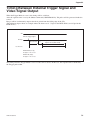
Timing Between External Trigger Signal and
Video Signal Output
When the Trigger Mode is set to 0, the timing will be as follows.
After the exposure time is set by the Shutter command (CSR F0F0081Ch), VD pulses will be generated inside the
camera.
Images will be isochronously output after the A period from the falling edge of the VD.
(The following figure shows an example where the frame rate is 7.5 fps for the DFW-SX910, and 15 fps for the
DFW-X710.)
VD
External Trigger Signal
Ext Trig.
Exposure Time
A
Approx. 120 ms (DFW-SX910)
Approx. 64 ms (DFW-X710)
Isochronous
DFW-SX910 (7.5 fps)
A: Approx. 1 ms or less
DFW-X710 (15fps)
A: Approx. 1 ms or less
The timing when the Trigger Mode is set to 1 is the same as above. In this case, the exposure time is defined by
the Trigger pulse width.
DFW-SX910/X710
34
Appendix
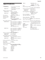
Specifications
Image sensor
DFW-SX910
1
/2-type progressive scan IT
transfer CCD
1
DFW-X710
/3-type progressive scan IT
transfer CCD
Number of effective pixels
DFW-SX910
Approx. 1,450,000
1392 (H) × 1040 (V)
DFW-X710
Approx. 800,000
1034 (H) × 779 (V)
Unit cell size
4.65 µm (H) × 4.65 µm (V)
Interface format
IEEE1394–1995
Transfer speed
400/200 Mbps
Protocol
IIDC 1394-based Digital
Camera Specification Version
1.30 Compliant
Image format (fixed size)
DFW-SX910
1280 × 960 YUV (4:2:2)/Mono8
1024 × 768 YUV (4:2:2)/Mono8
800 × 600 YUV (4:2:2)/Mono8
640 × 480 YUV (4:2:2/4:1:1)/
Mono8
320 × 240 YUV (4:2:2)
1024 × 768 YUV (4:2:2)/Mono8
800 × 600 YUV (4:2:2)/Mono8
640 × 480 YUV (4:2:2/4:1:1)/
Mono8
320 × 240 YUV (4:2:2)
Frame rate (depends on the image format)
DFW-SX910
7.5 to 1.875 fps
DFW-X710
15 to 1.875 fps
Image format (Format7) (for Partial scan)
DFW-SX910
1280 × 960 YUV (4:2:2/4:1:1)/
Mono8
DFW-X710
1024 × 768 YUV (4:2:2/4:1:1)/
Mono8
Partial scan function 16 × 16 (256 sections)
Lens mount
C-mount
Flange back
17.526 mm
Minimum illumination
20 lx (F0.95, Gain: +18 dB)
White balance
One Push/ATW/preset (3200 K,
5600 K)/manual
Hue
Adjustable
Saturation
Adjustable
Brightness
Adjustable
Gamma
Variable
CCD Iris
ON/OFF
DFW-X710
DFW-SX910/X710
Shutter
1/100,000 to 17.5 s
(Absolute value control
possible)
Gain
Auto/Manual (0 to +18 dB)
External trigger shutter
Available (Trigger Mode0/1)
Partial scan function (Smallest unit)
DFW-SX910
80 (H) × 60 (V)
DFW-X710
64 (H) × 48 (V)
Power supply/Power consumption
DC +8 to +30 V (from
IEEE1394 cable)
Power consumption 3.5 W (12 V)
Operating temperature
–5 to +45˚C
Storage temperature –20 to +60˚C
Operating relative humidity
20 to 80% (No condensation)
Storage relative humidity
20 to 95% (No condensation)
Vibration resistance 10 G (20 to 200 Hz, 20 minutes
for each direction-X, Y, Z)
MTBF
59549 Hrs (Approx. 6.8 years)
Shock resistance
70 G
Dimensions
44 (W) × 33 (H) × 116 (D) mm
Mass
250 g
Accessories
IEEE1394 cable (1)
Lens mount cap (1)
Operating Instructions (1)
35
Appendix
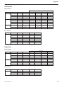
Video modes supported
DFW-SX910
Fixed format
Frame Rate
Format
Mode
Image Size
Color Coding
7.5
3.75
1.875
0
1
320 × 240
YUV4:2:2
a
a
–
2
640 × 480
YUV4:1:1
a
a
–
3
640 × 480
YUV4:2:2
a
a
–
5
640 × 480
Mono8
a
a
–
0
800 × 600
YUV4:2:2
a
a
–
1
15
2
800 × 600
Mono8
a
–
–
3
1024 × 768
YUV4:2:2
a
a
a
5
1024 × 768
Mono8
a
a
a
0
1280 × 960
YUV4:2:2
a
a
a
2
1280 × 960
Mono8
a
a
a
Format
Mode
Image Size
Color Coding
Partial Scan
Frame Rate
7
0
1280×960
Mono8
a (16×16)
Not specified
0
1280×960
YUV4:1:1
a (16×16)
Not specified
0
1280×960
YUV4:2:2
a (16×16)
Not specified
1
1280×960
Mono8
×
7.5/3.75 fps
1
1280×960
YUV4:1:1
×
7.5/3.75 fps
1
1280×960
YUV4:2:2
×
7.5/3.75 fps
1
1280×960
RAW8
×
7.5/3.75 fps
Format
Mode
Image Size
Color Coding
15
7.5
3.75
1.875
0
1
320 × 240
YUV4:2:2
a
a
a
–
2
640 × 480
YUV4:1:1
a
a
a
–
3
640 × 480
YUV4:2:2
a
a
a
–
5
640 × 480
Mono8
a
a
a
–
0
800 × 600
YUV4:2:2
a
a
a
–
2
800 × 600
Mono8
a
a
–
–
3
1024 × 768
YUV4:2:2
a
a
a
a
5
1024 × 768
Mono8
a
a
a
a
Format
Mode
Image Size
Color Coding
Partial Scan
Frame Rate
7
0
1024×768
Mono8
a (16×16)
Not specified
0
1024×768
YUV4:1:1
a (16×16)
Not specified
1
1024×768
YUV4:2:2
a (16×16)
Not specified
2
Free format
DFW-X710
Fixed format
Frame Rate
1
Free format
DFW-SX910/X710
36
Appendix
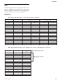
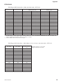
Notes on the frame rates in Partial Scan
Mode
The following table shows examples of frame rates in
Partial Scan Mode. Note that the values in the table are
given as examples, as the frame rate varies depending
on exposure times or areas you have specified.
DFW-X710
With Trigger OFF, Packet Size = 3072, and video mode = YUV4:2:2
Shutter=3 (9 µs)
Shutter=182 (33.1 ms)
Image Width
Image Height
Frame time (ms)
Frame rate (fps)
Frame time (ms)
Frame rate (fps)
1024
48
49.0
20.4
16.0
62.5
1024
96
52.1
19.2
19.0
52.6
1024
144
54.9
18.2
22.0
45.5
1024
192
58.8
17.0
26.0
38.5
1024
240
62.1
16.1
29.0
34.5
1024
288
64.9
15.4
31.9
31.3
1024
336
69.0
14.5
36.0
27.8
1024
384
71.9
13.9
39.1
25.6
1024
432
75.2
13.3
42.0
23.8
1024
480
78.7
12.7
46.1
21.7
1024
528
82.0
12.2
49.0
20.4
1024
576
84.7
11.8
52.1
19.2
1024
624
89.3
11.2
54.9
18.2
1024
672
91.7
10.9
58.8
17.0
1024
720
95.2
10.5
62.1
16.1
1024
768
99.0
10.1
65.8
15.2
With Trigger ON, Packet Size = 3072, Shutter = 182 (33.1 ms), and video mode = YUV4:2:2
Image Width
Image Height
Frequency of trigger
(Hz)
1024
48
30.0
1024
96
30.0
1024
144
30.0
1024
192
30.0
1024
240
30.0
1024
288
30.0
1024
336
27.7
1024
384
25.3
1024
432
23.3
1024
480
21.6
1024
528
20.1
1024
576
18.8
1024
624
17.7
1024
672
16.7
1024
720
15.9
1024
768
15.0
DFW-SX910/X710
Maximum frequency of an external
trigger shutter that can be input
Frame rates are affected by
exposure time.
37
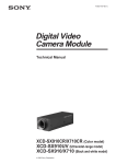
Appendix
DFW-SX910
With Trigger OFF, Packet Size = 2560, and video mode = YUV4:2:2
Shutter=3 (9 µs)
Shutter=182 (33.1 ms)
Image Width
Image Height
Frame time (ms)
Frame rate (fps)
Frame time (ms)
Frame rate (fps)
1280
60
65.8
15.2
34.0
29.4
1280
120
71.9
13.9
39.1
25.6
1280
180
78.1
12.8
45.0
22.2
1280
240
84.0
11.9
50.0
20.0
1280
300
89.3
11.2
55.9
17.9
1280
360
95.2
10.5
62.1
16.1
1280
420
100.0
10.0
67.1
14.9
1280
480
106.4
9.4
73.0
13.7
1280
540
112.4
8.9
78.7
12.7
1280
600
116.3
8.6
84.0
11.9
1280
660
123.5
8.1
90.1
11.1
1280
720
128.2
7.8
96.2
10.4
1280
780
133.3
7.5
101.0
9.9
1280
840
140.8
7.1
106.4
9.4
1280
1280
900
960
144.9
151.5
6.9
6.6
*1
4.4*1
*2
4.2*2
227.3
238.1
*1 At this setting, amount of data output from the camera exceeds the 1394 bus bandwidth limitation. Thus, the frame rate
reduces in half. Set the Shutter value to 22 (484 µs) or larger.
*2 Set the Shutter value to 49 (2.4 ms) or larger.
With Trigger ON, Packet Size = 2560, Shutter = 182 (33.12 ms), and video mode = YUV4:2:2
Image Width
Image Height
Frequency of trigger
(Hz)
1280
60
30.0
1280
120
25.2
1280
180
22.1
1280
240
19.5
1280
300
17.6
1280
360
16.0
1280
420
14.6
1280
480
13.5
1280
540
12.5
1280
600
11.7
1280
660
10.9
1280
720
10.3
1280
780
9.7
1280
840
9.2
1280
900
8.8
1280
960
8.4
DFW-SX910/X710
Maximum frequency of an external
trigger shutter that can be input
38
Appendix
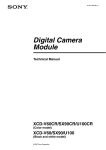
CCD Pixel Location (Top View)
DFW-SX910
Total number of pixels:
1434 (H) × 1050 (V)
Number of effective pixels: 1392 (H) × 1040 (V)
Number of output pixels:
1280 (H) × 960 (V) (Max.)
Size of unit cell: 4.65 µm (H) × 4.65 µm (V)
Output pixel area
2
V
960
56
1040
1280
40
8
1392
2
Effective pixel area
40
H
DFW-X710
Total number of pixels:
1077 (H) × 788 (V)
Number of effective pixels: 1034 (H) × 779 (V)
Number of output pixels:
1024 (H) × 768 (V)
Size of unit cell: 4.65 µm (H) × 4.65 µm (V)
Output pixel area
2
V
768
5
779
1024
6
7
3
1034
Effective pixel area
40
H
DFW-SX910/X710
39
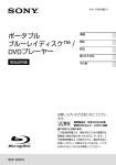
Appendix
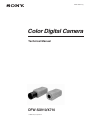
Spectral Sensitivity (Relative Response)
Parameters
(Without lens and light source parameters.)
DFW-SX910/X710
1
G
R
0.8
Relative Response
B
0.6
0.4
0.2
0
400
500
600
700
Wave Length [nm]
DFW-SX910/X710
40
Appendix
Dimensions
110
3.5
25.5
50
5
16.55
1
33.4
1" -32UNC
55
41
25
1/4" -20UNC
4-M3 (Effective
Depth 5)
13
56
Unit: mm
DFW-SX910/X710
41