1
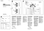
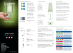
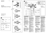
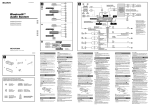
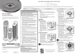
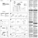
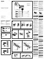
Cautions 4-149-706-11(1) *1 RCA pin cord (not supplied) *2 AUDIO OUT can be switched SUB or REAR. For details, see the supplied Operating Instructions. *1 *1 Cable con terminales RCA (no suministrado) *2 AUDIO OUT (salida de audio) puede cambiarse a SUB o REAR. Para obtener información, consulte el manual de instrucciones suministrado. L R from car antenna (aerial) desde la antena del automóvil System Car Audio REAR/SUB AUDIO OUT White Blanco Black Negro Caution Handle the bracket carefully to avoid injuring your fingers. 1 White/black striped Con rayas blancas y negras Gray Gris Right Derecho Blue Azul ANT REM Green Verde Installation/Connections Instalación/Conexiones Red Rojo Right Derecho Lista de componentes • Los números de la lista corresponden a los de las instrucciones. • La unidad se comercializa con el soporte y el marco de protección ya colocados. Antes de montarla, utilice las llaves de liberación para extraer el soporte de la misma. Para obtener más información, consulte “Extracción del marco de protección y del soporte ()”. • Conserve las llaves de liberación para utilizarlas en el futuro, ya que también las necesitará si retira la unidad del automóvil. Precaución Tenga mucho cuidado al manipular el soporte para evitar posibles lesiones en los dedos. Catch Note Before installing, make sure that the catches on both sides of the bracket are bent inwards 2 mm (3/32 in). If the catches are straight or bent outwards, the unit will not be installed securely and may spring out. 4 Green/black striped Con rayas verdes y negras Purple Morado • Esta unidad ha sido diseñada para alimentarse sólo con cc de 12 V de masa negativa. • No coloque los cables debajo de ningún tornillo, ni los aprisione con partes móviles (p. ej. los raíles del asiento). • Antes de realizar las conexiones, apague el automóvil para evitar cortocircuitos. • Conecte los cables de fuente de alimentación amarillo y rojo solamente después de haber conectado los demás. • Conecte todos los cables de conexión a masa a un punto común. • Por razones de seguridad, asegúrese de aislar con cinta aislante los cables sueltos que no estén conectados. • El uso de instrumentos ópticos con este producto aumenta el riesgo de sufrir daños oculares. Notas sobre el cable de fuente de alimentación (amarillo) • Cuando conecte esta unidad en combinación con otros componentes estéreo, la capacidad nominal del circuito conectado del automóvil debe ser superior a la suma del fusible de cada componente. • Si no hay circuitos del automóvil con capacidad nominal suficientemente alta, conecte la unidad directamente a la batería. 2 Max. supply current 0.1 A Corriente máx. de alimentación de 0,1 A Gray/black striped Con rayas grises y negras Left Izquierdo Notes on the power supply lead (yellow) • When connecting this unit in combination with other stereo components, the connected car circuit’s rating must be higher than the sum of each component’s fuse. • When no car circuits are rated high enough, connect the unit directly to the battery. • The numbers in the list are keyed to those in the instructions. • The bracket and the protection collar are attached to the unit before shipping. Before mounting the unit, use the release keys to remove the bracket from the unit. For details, see “Removing the protection collar and the bracket ().” • Keep the release keys for future use as they are also necessary if you remove the unit from your car. Blue/white striped Con rayas azules y blancas AMP REM Max. supply current 0.3 A Corriente máx. de alimentación de 0,3 A Left Izquierdo • This unit is designed for negative ground (earth) 12 V DC operation only. • Do not get the leads under a screw, or caught in moving parts (e.g. seat railing). • Before making connections, turn the car ignition off to avoid short circuits. • Connect the yellow and red power supply leads only after all other leads have been connected. • Run all ground (earth) leads to a common ground (earth) point. • Be sure to insulate any loose unconnected leads with electrical tape for safety. • The use of optical instruments with this product will increase eye hazard. Parts Iist REAR / SUB Fuse (10 A) AUDIO OUT*2 Fusible (10 A) 3 Precauciones Connection Yellow Amarillo Conexión Connection example 5 Purple/black striped Con rayas moradas y negras Notes • Be sure to connect the ground (earth) lead before connecting the amplifier. • The alarm will only sound if the built-in amplifier is used. CXS-GT09HP Connection diagram ©2009 Sony Corporation Printed in Thailand Ejemplo de conexiones Notas • Asegúrese de conectar primero el cable de conexión a masa antes de realizar la conexión del amplificador. • La alarma sonará únicamente si se utiliza el amplificador incorporado. Diagrama de conexión To a metal surface of the car First connect the black ground (earth) lead, then connect the yellow and red power supply leads. Welcome ! To the power antenna (aerial) control lead or power supply lead of antenna (aerial) booster Bienvenido Thank you for purchasing the CXS-GT09HP. This package includes the following: • Car audio unit CDX-GT09 • Speaker 6 × 9 Speaker 6 1/2 Speaker Gracias por adquirir el modelo CXS-GT09HP. El paquete incluye los siguientes: • Unidad de audio para automóvil CDX-GT09 • Altavoz Altavoz de 6 × 9 Altavoz de 6 1/2 For details on how to install the car audio unit, see the front side of these instructions. For details on how to install the speakers, see the reverse side of these instructions. Para obtener más información acerca de la instalación de la unidad de audio para el automóvil, consulte la parte frontal de estas instrucciones. Para obtener más información acerca de la instalación de los altavoces, consulte la contraportada de estas instrucciones. For details on operation, see the manual of CDX-GT09. 1 2 Para obtener más información acerca del funcionamiento de esta unidad, consulte el manual del modelo CDXGT09. Notes • It is not necessary to connect this lead if there is no power antenna (aerial) or antenna (aerial) booster, or with a manually-operated telescopic antenna (aerial). • When your car has a built-in FM/AM antenna (aerial) in the rear/side glass, see “Notes on the control and power supply leads.” Face the hook inwards. To AMP REMOTE IN of an optional power amplifier El gancho debe encontrarse en la parte interior. To the +12 V power terminal which is energized in the accessory position of the ignition switch This connection is only for amplifiers. Connecting any other system may damage the unit. Notes • If there is no accessory position, connect to the +12 V power (battery) terminal which is energized at all times. Be sure to connect the black ground (earth) lead to a metal surface of the car first. • When your car has a built-in FM/AM antenna (aerial) in the rear/side glass, see “Notes on the control and power supply leads.” Memory hold connection When the yellow power supply lead is connected, power will always be supplied to the memory circuit even when the ignition switch is turned off. 1 2 3 Notes on speaker connection • Before connecting the speakers, turn the unit off. • Use speakers with an impedance of 4 to 8 ohms, and with adequate power handling capacities to avoid its damage. • Do not connect the speaker terminals to the car chassis, or connect the terminals of the right speakers with those of the left speaker. • Do not connect the ground (earth) lead of this unit to the negative (–) terminal of the speaker. • Do not attempt to connect the speakers in parallel. • Connect only passive speakers. Connecting active speakers (with built-in amplifiers) to the speaker terminals may damage the unit. • To avoid a malfunction, do not use the built-in speaker leads installed in your car if the unit shares a common negative (–) lead for the right and left speakers. • Do not connect the unit’s speaker leads to each other. Dashboard Tablero ×4 182 mm Equipment used in illustrations (not supplied) Equipo utilizado en las ilustraciones (no suministrado) Note on connection If speaker and amplifier are not connected correctly, “FAILURE” appears in the display. In this case, make sure the speaker and amplifier are connected correctly. 53 m Rear speaker Altavoz posterior Conecte primero el cable de conexión a masa negro, y después los cables amarillo y rojo de fuente de alimentación. Al cable de control de la antena motorizada o al cable de fuente de alimentación del amplificador de señal de la antena Notas • Si no se dispone de antena motorizada ni de amplificador de antena, o se utiliza una antena telescópica accionada manualmente, no será necesario conectar este cable. • Si el automóvil incorpora una antena de FM/AM en el cristal trasero o lateral, consulte “Notas sobre los cables de control y de fuente de alimentación”. A AMP REMOTE IN de un amplificador de potencia opcional Esta conexión es sólo para amplificadores. La conexión de cualquier otro sistema puede dañar la unidad. Al terminal de alimentación de +12 V que recibe energía en la posición de accesorio del interruptor de encendido Notas • Si no hay posición de accesorio, conéctelo al terminal de alimentación (batería) de +12 V que recibe energía sin interrupción. Asegúrese de conectar primero el cable de conexión a masa negro a una superficie metálica del automóvil. • Si el automóvil incorpora una antena de FM/AM en el cristal trasero o lateral, consulte “Notas sobre los cables de control y de fuente de alimentación”. Be sure to connect the black ground (earth) lead to a metal surface of the car first. ×2 A una superficie metálica del automóvil To the +12 V power terminal which is energized at all times Notes on the control and power supply leads • The power antenna (aerial) control lead (blue) supplies +12 V DC when you turn on the tuner. • When your car has built-in FM/AM antenna (aerial) in the rear/side glass, connect the power antenna (aerial) control lead (blue) or the accessory power supply lead (red) to the power terminal of the existing antenna (aerial) booster. For details, consult your dealer. • A power antenna (aerial) without a relay box cannot be used with this unit. m Installation Power amplifier Amplificador de potencia Preparation Claws Uñas • Choose the installation location carefully so that the unit will not interfere with normal driving operations. • Avoid installing the unit in areas subject to dust, dirt, excessive vibration, or high temperatures, such as in direct sunlight or near heater ducts. • Use only the supplied mounting hardware for a safe and secure installation. Active subwoofer Altavoz potenciador de graves activo Mounting angle adjustment Adjust the mounting angle to less than 45°. Removing the protection collar and the bracket A TOYOTA B NISSAN size 5 × max. 8 mm (7/32 × max. 5/16 in) Tamaño 5 × 8 mm máx. 2 size 5 × max. 8 mm (7/32 × max. 5/16 in) Tamaño 5 × 8 mm máx. to dashboard/center console al tablero o consola central Al terminal de alimentación de +12 V que recibe energía sin interrupción Asegúrese de conectar primero el cable de conexión a masa negro a una superficie metálica del automóvil. Notas sobre los cables de control y de fuente de alimentación • El cable de control de la antena motorizada (azul) suministrará cc de + 12 V cuando conecte la alimentación del sintonizador. • Si el automóvil dispone de una antena de FM/AM incorporada en el cristal trasero o lateral, conecte el cable de control de antena motorizada (azul) o el cable de fuente de alimentación auxiliar (rojo) al terminal de alimentación del amplificador de antena existente. Para obtener más información, consulte a su distribuidor. • Con esta unidad no es posible utilizar una antena motorizada sin caja de relé. Conexión para protección de la memoria Si conecta el cable de fuente de alimentación amarillo, el circuito de la memoria recibirá siempre alimentación, aunque apague el interruptor de encendido. Notas sobre la conexión de los altavoces • Antes de conectar los altavoces, desconecte la alimentación de la unidad. • Utilice altavoces con una impedancia de 4 a 8 Ω con la capacidad de potencia adecuada para evitar que se dañen. • No conecte los terminales de altavoz al chasis del automóvil, ni conecte los terminales del altavoz derecho con los del izquierdo. • No conecte el cable de conexión a masa de esta unidad al terminal negativo (–) del altavoz. • No intente conectar los altavoces en paralelo. • Conecte solamente altavoces pasivos. Si conecta altavoces activos (con amplificadores incorporados) a los terminales de altavoz, puede dañar la unidad. • Para evitar fallas de funcionamiento, no utilice los cables de altavoz incorporados instalados en el automóvil si la unidad comparte un cable negativo común (–) para los altavoces derecho e izquierdo. • No conecte los cables de altavoz de la unidad entre sí. Nota sobre la conexión Si el altavoz y el amplificador no están conectados correctamente, aparecerá “FAILURE” en la pantalla. Si es así, compruebe la conexión de ambos dispositivos. Instalación Preparación • Elija cuidadosamente el lugar de montaje de forma que la unidad no interfiera con las funciones normales de conducción. • Evite instalar la unidad donde pueda quedar sometida a polvo, suciedad, vibraciones excesivas o altas temperaturas como, por ejemplo, a la luz solar directa o cerca de conductos de calefacción. • Para realizar una instalación segura y firme, utilice solamente la ferretería de montaje suministrada. Ajuste del ángulo de montaje Ajuste el ángulo de montaje a menos de 45°. Before installing the unit, remove the protection collar and the bracket from the unit. 1 Remove the protection collar . Pinch both edges of the protection collar , then to dashboard/center console al tablero o consola central pull it out. Remove the bracket . Insert both release keys together between the unit and the bracket until they click. Pull down the bracket , then pull up the unit to separate. Mounting example REAR / SUB AUDIO OUT Enganche Nota Antes de instalar la unidad, compruebe que los enganches de ambos lados del soporte están doblados hacia adentro 2 mm. Si no lo están o están doblados hacia afuera, la unidad no se instalará correctamente y puede saltar. Extracción del marco de protección y del soporte Antes de instalar la unidad, retire el marco de protección y el soporte de la misma. 1 Retire el marco de protección . 2 Retire el soporte . Apriete ambos bordes del marco de protección y, a continuación, tire de él hacia fuera. Inserte ambas llaves de liberación entre la unidad y el soporte hasta que encajen. Presione el soporte y, a continuación, levante la unidad para separar ambos elementos. Installation in the dashboard Notes • Bend these claws outward for a tight fit, if necessary (-2). • Make sure that the 4 catches on the protection collar are properly engaged in the slots of the unit (-3). Bracket Soporte size 5 × max. 8 mm (7/32 × max. 5/16 in) Tamaño 5 × 8 mm máx. Bracket Soporte size 5 × max. 8 mm (7/32 × max. 5/16 in) Tamaño 5 × 8 mm máx. Mounting the unit in a Japanese car You may not be able to install this unit in some makes of Japanese cars. In such a case, consult your Sony dealer. Note To prevent malfunction, install only with the supplied screws . Bracket Soporte Bracket Soporte Existing parts supplied with your car Piezas existentes suministradas con su automóvil Existing parts supplied with your car Piezas existentes suministradas con su automóvil How to detach and attach the front panel Before installing the unit, detach the front panel. -A To detach Before detaching the front panel, be sure to press . Press , and pull it off towards you. REAR / SUB AUDIO OUT -B To attach A B Engage part of the front panel with part of the unit, as illustrated, and push the left side into position until it clicks. Ejemplo de montaje Instalación en el tablero Notas • Si es necesario, doble estos uñas hacia fuera para que encaje firmemente (-2). • Compruebe que los 4 enganches del marco de protección estén bien fijados en las ranuras de la unidad (-3). Montaje de la unidad en un automóvil japonés Es posible que no pueda instalar esta unidad en algunos automóviles japoneses. En tal caso, consulte a su distribuidor Sony. Nota Para evitar que se produzcan fallas de funcionamiento, realice la instalación solamente con los tornillos suministrados . Forma de extraer e instalar el panel frontal Antes de instalar la unidad, extraiga el panel frontal. -A Para extraerlo Antes de extraer el panel frontal, asegúrese de presionar . Después presione y tire de él hacia usted. -B Para instalarlo Warning if your car’s ignition has no ACC position Be sure to set the Auto Off function. For details, see the supplied Operating Instructions. The unit will shut off completely and automatically in the set time after the unit is turned off, which prevents battery drain. If you do not set the Auto Off function, press and hold until the display disappears each time you turn the ignition off. Coloque el orificio del panel frontal en el eje de la unidad y, a continuación, presione ligeramente el lado izquierdo hacia adentro. Advertencia: si el encendido del automóvil no dispone de una posición ACC Asegúrese de ajustar la función de desconexión automática. Para obtener más información, consulte el manual de instrucciones suministrado. La unidad se apagará completa y automáticamente en el tiempo establecido después de que se desconecte la unidad, lo que evita que se desgaste la batería. Si no ha ajustado la función de desconexión automática, mantenga presionado cada vez que apague el interruptor de encendido, hasta que la pantalla desaparezca. Parts list Lista de las piezas 3/4 6 × 9 Speaker Altavoz de 6 × 9 6 1/2 Speaker Altavoz de 6 1/2 6 × 9 Speaker Altavoz de 6 × 9 6 1/2 Speaker Altavoz de 6 1/2 ×2 3-way Speaker (6 × 9 Speaker) 2-way Speaker (6 / Speaker) 12 ø 4 (3/16) × 30 (1 3/16) × 16 0.3 m (11 7/8 in) ×4 ×2 A depth of at least 75 mm / 3 in (44 mm / 1 in)* is required for flush mounting. Measure the depth of the area where you are to mount the speaker, and ensure that the speaker is not obstructing any other components of the car. Keep the following in mind when choosing a mounting location: • Make sure that nothing is obstructing around the mounting location of the door (front or rear) or the rear tray where you are to mount the speaker. • A hole for mounting may already be cut out of the inner panel of the door (front or rear) or the rear tray. In this case, you need to modify the board only. • If you are to mount this speaker system in the door (front or rear), make sure that the speaker terminals, frame or magnet do not interfere with any inner parts, such as the window mechanism in the door (when you open or close the window), etc. Also make sure that the speaker grille does not touch any inner fittings, such as the window cranks, door handles, arm rests, door pockets, lamps or seats etc. • If you are to mount this speaker system in the rear tray, make sure that the speaker terminals, frame or magnet do not touch any inner parts of the car, such as the torsion bar springs (when you open or close the trunk lid), etc. Also make sure that the speaker grille does not touch any inner fittings, such as seat belts, head rests, center brake lights, inner covers of the rear wipers, curtains or air purifiers, etc. × 16 Mounting from the car interior Montaje desde el interior del automóvil DOOR (FRONT/REAR) PUERTA (FRONTAL/POSTERIOR) 1 REAR TRAY BANDEJA POSTERIOR Mark the 4 bolt holes and make them 3.2 mm* (1/8 in) in diameter. Marque los orificios para los 4 pernos y haga agujeros de 3,2 mm* de diámetro. * When using : ø 5 mm * Si utiliza : ø 5 mm Antes del montaje Before mounting (7/32 1 * (6 1/2 Speaker) Precautions Mark the 4 bolt holes and make them 3.2 mm* (1/8 in) in diameter. Marque los orificios para los 4 pernos y haga agujeros de 3,2 mm* de diámetro. * When using : ø 5 mm * Si utiliza : ø 5 mm in) Unit: mm (in) Unidad: mm (7/32 in) Unit: mm (in) Unidad: mm • Do not continuously use the speaker system beyond the peak power handling capacity. • Keep recorded tapes, watches, and personal credit cards using magnetic coding away from the speaker system to protect them from damage caused by the magnets in the speakers. If you cannot find an appropriate mounting location, consult your car dealer or your nearest Sony dealer before mounting. ø 3.2 (1/8) ø 3.2 (1/8) 223 (8 7/8) Instructions Instrucciones Specifications 6 × 9 Speaker Speaker 154 (6 1/8) Rear tray Bandeja posterior ø 126 (5) CXS-GT09HP Door Puerta Peak power Rated power Impedance Sensitivity Frequency response Mass 2 2 Dimensions Dimensiones Supplied accessory 6 1/2 Speaker Speaker Unit: mm (in) Unidad: mm Peak power Rated power Impedance Sensitivity Frequency response Mass Striped cord Cable con rayas 6 × 9 Speaker Altavoz de 6 × 9 4.5 × 7.5 (3/16 × 5/16) Striped cord Cable con rayas Supplied accessory Coaxial 3-way: Woofer 16 × 24 cm (6 3/8 × 9 1/2 in), cone type Midrange 5.5 cm (2 1/4 in), cone type Tweeter 1.4 cm (9/16 in), balanced dome type 300 W 60 W 4Ω 93 dB/W/m 27 – 30,000 Hz Approx. 1,150 g (2 lb 9 oz) per speaker Parts for installation Coaxial 2-way: Woofer 16 cm (6 3/8 in), HOP, cone type Tweeter 4 cm (1 5/8 in), Al, cone type 190 W 40 W 4Ω 90 dB/W/m 35 – 22,000 Hz Approx. 560 g (1 lb 4 oz) per speaker Parts for installation 237 (9 3/8) 222 (8 3/4) ø 80 (3 1/4) 166 (6 5/8) 264 (10 1/2) Design and specifications are subject to change without notice. To speaker cord of a car. Al cable del altavoz del automóvil. 117 (4 5/8) 194 (7 3/4) 16 (21/32) 153 (6 1/8) 35 (1 7/16) 168 (6 To speaker cord of a car. Al cable del altavoz del automóvil. 3 5 2. 6 1/2 Speaker Altavoz de 6 1/2 75 (3) 5/8) (1 5 (7 /32 ) /8) 3 ø 142 (5 5/8) Unit: mm (in) Unidad: mm ø 125 (5) 32) ø 75 (3) (17 / ø 158 (6 1/4) 13 1 ø 168 (6 3/4) 27 (1 1/8) ø 5 (7/32) 8.9 (3/8) 44 (1 3/4) (1 ) /16 Para el montaje alineado, es necesaria una profundidad mínima de 75 mm (44 mm)*. Mida la profundidad del lugar donde desea montar el altavoz y compruebe que el altavoz no obstruya ningun componente del automóvil. Antes de elegir el lugar de montaje, se debe tener en cuenta lo siguiente: • Asegúrese de que no haya obstáculos en el lugar de montaje de la puerta (frontal o posterior) ni en la bandeja posterior donde desea instalar el altavoz. • Es posible que ya exista un orificio de montaje en el panel interior de la puerta (frontal o posterior) o en la bandeja posterior. En este caso, sólo debe modificar el tablero. • Si desea montar este sistema de altavoces en la puerta (frontal o posterior), asegúrese de que los terminales del altavoz, el marco y el imán no interfieren con los components interiores como, por ejemplo, el mecanismo de la ventanilla de la puerta (al abrir o cerrar la ventanilla), etc. Asegúrese también de que la rejilla del altavoz no está en contacto con accesorios interiores como, por ejemplo, los picaportes de las ventanillas y puertas, los reposabrazos, los compartimentos para guardar objetos situados en las puertas, las luces o los asientos, etc. • Si desea montar el sistema de altavoces en la bandeja posterior, asegúrese de que los terminales del altavoz, el marco y el imán no están en contacto con los componentes interiores del automóvil como, por ejemplo, los resortes de la barra de torsión (cuando abra o cierre el portaequipajes), etc. Asegúrese también de que la rejilla del altavoz no está en contacto con accesorios interiores como, por ejemplo, los cinturones de seguridad, los reposacabezas, las luces de frenos centrales, las cubiertas interiores de los limpiaparabrisas posteriores, las cortinas o ambientadores, etc. * (Altavoz de 6 1/2) Precauciones • Procure no utilizar el sistema de altavoces de forma continua con una potencia que sobrepase la potencia admisible. • Mantenga alejados del sistema de altavoces las cintas grabadas, relojes o tarjetas de crédito con codificación magnética para evitar daños que posiblemente causarían los imanes de los altavoces. Si no encuentra un emplazamiento apropiado para el montaje, consulte al distribuidor de su automóvil o al proveedor de Sony más próximo. Especificaciones Altavoz de 6 × 9 Altavoz Potencia máxima Potencia nominal Impedancia Sensibilidad Respuesta de frecuencia Peso Accesorios suministrados Altavoz de 6 1/2 Altavoz Potencia máxima Potencia nominal Impedancia Sensibilidad Respuesta de frecuencia Peso Accesorios suministrados Coaxial de 3 vías: Graves de 16 × 24 cm, tipo cono Medios de 5,5 cm, tipo cono Agudos de 1,4 cm, equilibrado tipo cúpula 300 W 60 W 4Ω 93 dB/W/m 27 – 30 000 Hz Aprox. 1 150 g por altavoz Componentes para instalación Coaxial de 2 vías: Graves de HOP de 16 cm, tipo cono Agudos de Al de 4 cm, tipo cono 190 W 40 W 4Ω 90 dB/W/m 35 – 22 000 Hz Aprox. 560 g por altavoz Componentes para instalación Diseño y especificaciones sujetos a cambio sin previo aviso.