1
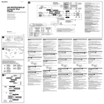
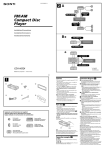
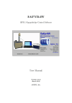
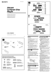
3-241-107-21 (1)
2
A
AUDIO OUT
FRONT
SUB OUT (MONO)
FM/MW/LW
Compact Disc
Player
AUDIO OUT
REAR
Installation/Connections
B
BUS AUDIO IN
BUS CONTROL IN
BUS AUDIO IN
Source selector*
*
XA-C30
BUS CONTROL IN
* not supplied
CDX-CA900
Sony Corporation © 2002 Printed in Thailand
1
1
2
3
4
×4
5
6
7
×2
8
9
q;
Cautions
Connection example (2)
• This unit is designed for negative earth 12 V
DC operation only.
• Do not get the wires under a screw, or caught
in moving parts (e.g. seat railing).
• Before making connections, turn the car
ignition off to avoid short circuits.
• Connect the yellow and red power input leads
only after all other leads have been connected.
• Run all earth wires to a common earth
point.
• Be sure to insulate any loose unconnected
wires with electrical tape for safety.
Notes (2-A)
• Be sure to connect the earth cord before
connecting the amplifier.
• If you connect an optional power amplifier and do
not use the built-in amplifier, the beep sound will
be deactivated.
Notes on the power supply cord (yellow)
• When connecting this unit in combination with
other stereo components, the connected car
circuit’s rating must be higher than the sum of
each component’s fuse.
• When no car circuits are rated high enough,
connect the unit directly to the battery.
⊕ Κ3 × 12
Parts Iist (1)
The numbers in the list are keyed to those in the
instructions.
Caution
Equipment used in illustrations (not supplied)
Handle the bracket 1 carefully to avoid injuring
your fingers.
Front speaker
Power amplifier
Rear speaker
CD/MD changer
Active subwoofer
Rotary commander RM-X4S
Tip (2-B- )
For connecting two or more CD/MD changers, the
source selector XA-C30 (optional) is necessary.
Connection diagram (3)
1 To a metal surface of the car
First connect the black earth lead, then connect
the yellow and red power input leads.
2 To the power aerial control lead or power
supply lead of aerial booster amplifier
Notes
• It is not necessary to connect this lead if there
is no power aerial or aerial booster, or with a
manually-operated telescopic aerial.
• When your car has a built-in FM/MW/LW aerial
in the rear/side glass, see “Notes on the control
and power supply leads.”
3 To AMP REMOTE IN of an optional power
amplifier
This connection is only for amplifiers. Connecting
any other system may damage the unit.
4 To the interface cable of a car telephone
5 To a car’s illumination signal
Be sure to connect the black ground lead to it
first.
6 To the +12 V power terminal which is energized
in the accessory position of the ignition key
switch
Notes
• If there is no accessory position, connect to the
+12 V power (battery) terminal which is
energised at all times.
Be sure to connect the black earth lead to it
first.
• When your car has a built-in FM/MW/LW aerial
in the rear/side glass, see “Notes on the control
and power supply leads.”
7 To the +12 V power terminal which is energised
at all times
Be sure to connect the black earth lead to it first.
3
Supplied with XA-C30
*1
*3
Source selector
(not supplied)
Supplied with the CD/MD changer
*2
XA-C30
SUB OUT (MONO)
BUS AUDIO IN
/AUX IN*4
AUDIO OUT
FRONT
*1 RCA pin cord (not supplied)
REMOTE IN
*2 Auxiliary optional equipment
such as portable DVD player (not
supplied)
*5
L
*1
R
from car aerial
BUS
AUDIO
AUDIO OUT AUDIO OUT
REAR
FRONT
AUDIO OUT
REAR
*3 supplied with the auxialiry
equipment
BUS
CONTROL IN
*4 Be sure to match the colourcoded code for audio to the
appropriate jacks from the unit.
If you connect a optional unit,
you cannot use AUX IN terminal.
Fuse (10 A)
Blue/white striped
3
7
AMP REM
Black
Max. supply current 0.3 A
1
White
Blue
Left
*5 Insert with the cord upwards
ANT REM
White/black striped
Grey
2
Max. supply current 0.1 A
Light blue
ATT
4
Right
Grey/black striped
Orange/white striped
ILLUMINATION
5
Green
Left
Red
Green/black striped
Purple
6
Yellow
Right
7
Purple/black striped
Notes on the control and power supply leads
• The power aerial control lead (blue) supplies +12 V
DC when you turn on the tuner or when you
activate the AF (Alternative Frequency), TA (Traffic
Announcement) function.
• When your car has built-in FM/MW/LW aerial in
the rear/side glass, connect the power aerial
control lead (blue) or the accessory power input
lead (red) to the power terminal of the existing
aerial booster. For details, consult your dealer.
• A power aerial without relay box cannot be used
with this unit.
Memory hold connection
When the yellow power input lead is connected,
power will always be supplied to the memory circuit
even when the ignition key is turned off.
Notes on speaker connection
• Before connecting the speakers, turn the unit off.
• Use speakers with an impedance of 4 to 8 ohms,
and with adequate power handling capacities to
avoid its damage.
• Do not connect the speaker terminals to the car
chassis, or connect the terminals of the right
speakers with those of the left speaker.
• Do not connect the earth lead of this unit to the
negative (–) terminal of the speaker.
• Do not attempt to connect the speakers in parallel.
• Connect only passive speakers. Connecting active
speakers (with built-in amplifiers) to the speaker
terminals may damage the unit.
• To avoid a malfunction, do not use the built-in
speaker wires installed in your car if the unit shares
a common negative (–) lead for the right and left
speakers.
• Do not connect the unit’s speaker cords to each
other.
2
•
•
2
•
•
•
•
•
•
2
•
•
•
3
•
1
•
2
•
•
•
•
•
1
•
•
•
•
3
•
4
5
1
6
•
•
7
4 A
B
5 1
2
3
4
*
Dashboard
1
Fire wall
6
4
4
x
2
5
1
2
Bend these claws outward
for a tight fit, if necessary.
A
5
1
B
5
B NISSAN
6 A TOYOTA
7
4
Releasing the rotary commander
Mounting example
(PUSH)
1
4
4
3
Markings
Infrared rays dial
max. size
5 × 8 mm
max. size
5 × 8 mm
2
1
1
to dashboard/centre console
9
to dashboard/centre console
2
Mark
4
Bracket
max. size
5 × 8 mm
4
Bracket
max. size
5 × 8 mm
4
5
6
the other hole
Heavy duty tape etc.
9
q;
Bracket
Bracket
8
Existing parts supplied with your car
Precautions
•Choose the installation location carefully so that
the unit will not interfere with normal driving
operations.
•Avoid installing the unit in areas subject to dust,
dirt, excessive vibration, or high temperatures,
such as in direct sunlight or near heater ducts.
•Use only the supplied mounting hardware for a
safe and secure installation.
Mounting the unit in a Japanese
car (6)
Installing the rotary commander
(7)
You may not be able to install this unit in some
makes of Japanese cars. In such a case, consult
your Sony dealer.
Notes
• Choose the mounting location carefully so that the
rotary commander will not interfere with operating
the car.
• Install the rotary commander on a flat surface with a
circular area of approximate 55 mm diameter.
• Do not install the rotary commander where it may
jeopardize the safety of the (front) passenger in
anyway.
• When installing the rotary commander, be sure not
to damage the electrical cables etc. on the other side
of the mounting surface.
• Avoid installing the rotary commander where it may
be subject to high temperatures, such as from direct
sunlight or hot air from the heater etc.
Note
To prevent malfunction, install only with the supplied
screws 4.
Mounting angle adjustment
Adjust the mounting angle to less than 60°.
How to detach and attach the
front panel (4)
Before installing the unit, detach the front
panel.
4-A To detach
Before detaching the front panel, be sure to press
(OFF). Press (OPEN), then slide the front panel
to the right side, and pull out the left side.
4-B
To attach
Place the hole
in the front panel onto the
spindle on the unit as illustrated, then push the
left side in.
Warning when installing in a car
without ACC (accessory) position
on the ignition key switch
Be sure to press (OFF) on the unit for two
seconds to turn off the clock display after
turning off the engine.
When you press (OFF) only momentarily, the
clock display does not turn off and this causes
battery wear.
RESET button
When the installation and connections are
completed, be sure to press the RESET button
with a ballpoint pen, etc., after removing the front
panel.
When installing the unit on the steering
column cover
1 Choose the exact location for the rotary
commander to be mounted temporarily,
then press the buttons and rotate the
controls to make sure that your master unit
reacts well.
You can change the direction of infrared rays
by turning the dial on the rotary commander.
Caution
Be sure that the place where you install the rotary
commander is within the range of the receptor on
the unit.
2 Clean the mounting surface.
Dirt or oil impair the adhesive strength of the
double-sided adhesive tape preattached to the
mounting holder 9.
Mounting example (5)
Installation in the dashboard
Note (5-*)
When installing this unit: Depending on car
type, the mounting angle may not allow the
front panel to open easily. In such a case,
remove the silver screw A shown below.
When screwing it on again, first lock the lever B.
Attaching the screw without doing so may cause
the unit to break.
q;
Existing parts supplied with your car
5 Warm the mounting surface and the doublesided adhesive tape on the mounting holder
9 with a hair drier, etc., to a temperature
between 20 °C and 30 °C, and attach the
mounting holder 9 onto the mounting
surface by applying even pressure. Then
screw it down with the screw 8.
Attach a piece of heavy duty tape etc. on the
other side of the mounting surface to cover the
protruding tip of the screw so that they will not
interfere with the electrical cables etc. inside
the steering wheel column.
6
•
•
•
•
•
•
q;
•
•
•
q;
4
(OFF)
(OFF)
4
(OFF)
(OPEN)
9
Cautions
• If the master unit or the rotary commander is
exposed to direct sunlight, sensitivity of the
infrared receptor or emitter may deteriorate and
the master unit may not work properly. If this
happens, rotate the dial to readjust the direction of
infrared rays.
• Be sure to attach the supplied strap q; when
installing the rotary commander near the steering
wheel.
• Be sure that the strap q; does not get caught on the
car controls (gear, shifter, etc.).
• Be sure to tighten the stopper of the strap q; after
hanging the strap q; on the indicator switch, etc.
Note
Make sure the orientation of the markings on both
the mounting holder and the rotary commander is
the same, and then attach.
4 Remove the steering wheel column cover,
and drill 2 mm diameter hole where you
have marked.
Tip
There are two holes for the strap q;. You can use
whichever hole you prefer.
Note
If you are mounting the rotary commander to the
steering wheel column, make sure that the
protruding tip of the screw on the inner surface of
the column do not in anyway hinder or interfere with
the movement of the rotating shaft, operative parts
of the switches or the electrical cables etc. inside the
column.
q;
q;
•
Note
Choose the mounting location carefully. The
adhesive is very strong and relocation may be
difficult.
Tighten the screw firmly so that the screw head
does not protrude.
6 After installing the steering wheel column
cover, attach the rotary commander to the
mounting holder until it locks into place as
illustrated.
q;
•
4
4
9
5
5
9
*
°C
°C
9
3 Mark the position for the supplied screw.
Use the screw hole on the mounting holder 9
to mark the position.
•
7
8
A
B