1
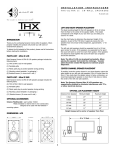
INSTALLATION INSTRUCTIONS
V C 3 0 R R O T A R Y
S T E R E O V O L U M E
PN.33-1517 9/98
I N - W A L L
C O N T R O L
INTRODUCTION
3. Repeat step 2 for the right or Channel-B speaker output.
Thank you for purchasing this Sonance® component. Sonance
also offers the largest selection of high fidelity in-wall/
in-ceiling speakers in the world. Consult Sonance literature or
your Authorized Sonance Dealer for more information on the
wide variety of speakers, amplifiers, switchers, controls, cable,
and other custom installation products available from Sonance.
4. Connect the left speaker wires to the left or Channel-A
output terminals of the volume control. Check proper polarity
of wires for correct speaker phase. For example connect the +
terminal of the speaker to the + VC output, and - to (see diagram 2).
5. Repeat step 4 for the right or Channel-B speaker connection.
Please read these instructions carefully before connecting this
device to your system. If connections are made incorrectly you
may damage your amplifier/receiver.
MOUNTING THE CONTROLS:
IMPORTANT NOTE: TURN YOUR AMPLIFIER/RECEIVER OFF
BEFORE ATTEMPTING THE FOLLOWING HOOK-UP PROCEDURES.
Once the unit has been wired, position the volume control with
terminals at top, and attach it to a standard light switch plaster
ring or J-box. Use the included screws to attach the
volume control to the plaster ring or box. Attach the wallplate
to the control using the screws provided. DO NOT OVERTIGHTEN THE PLATE SCREWS OR YOU MAY DAMAGE THE
PLATE. Finally, attach the knob to the control shaft
(See Diagram 3).
VC30R APPLICATIONS
The VC30R is a rotary volume control. The volume can be
controlled by turning the knob clockwise to increase volume
and counterclockwise to decrease volume. This 10 position
rotary knob incorporates light touch silent switching
capabilities and can safely handle 30 watts per channel
of power.
OPERATION
Determine the maximum volume you wish to feed to the rooms
in which you have volume controls and speakers. With your
house music source (amplifier/receiver) turned down, turn the
volume control(s) all the way up. Feed the amplifier/receiver a
strong music signal, then gradually increase the
amplifier/receiver volume until the volume in the room(s) is as
loud as you are likely to ever listen. Take particular care that no
audible distortion is heard through your speakers or speaker
damage will occur. If you are using an amplifier with input level
controls, such as the Sonance Sonamp® series amplifiers, adjust
the level controls appropriately. Then return to the rooms with
volume controls and lower the volume settings to normal
listening levels. Setting the maximum volume will ensure safe
operation for speakers and amplifiers. If you think there should
be sound coming from your speakers but do not hear anything
when the VC is turned all the way up, DO NOT leave it in the
full ON position when checking your sources or source
material. Otherwise there may be a startling increase in
volume when the problem is remedied, and speaker damage
may occur.
WIRING AND PLACEMENT
DO NOT mount the volume control in the same electrical box
with AC house wiring, light switches, dimmers, or any other
high voltage device or control. The VC can share gang boxes
with other low voltage controls such as A/B speaker switches,
infrared receivers and emitters, and other volume controls if
these other devices are rated as Class 2 devices by the National
Electrical Code. With 14-18 gauge wire the volume control
between a single pair of speakers and the amplifier powering
those speakers. Run four wires for carrying speaker signals
(L+, L-, R+, and R-) from the amplifier, through the walls or
ceiling, to the volume control.We recommend high quality wire
like Sonance MediaLinQ®. If using free standing speakers, run
the wire through the wall or ceiling to a convenient location
near the speaker and terminate it with a Sonance FielDress™
series system terminator or other audio jack.
INSTALLATION FOR VC30R (SEE DIAGRAM 1)
SPECIFICATIONS
1.Once the speaker wires have been run, install a standard light
switch plaster ring or J-box that is approximately 3” in depth,
available from an electrical supply source.
Power Rating:
2. TURN THE AMPLIFIER/RECEIVER POWER OFF. Then
connect the left or Channel-A speaker output, of the
amplifier/receiver, to the left screw-to-connect input terminals
of the volume control, observing proper polarity. For example
connect L+ of the amplifier to L+ of the VC, and L- to L(see diagram 2).
30 Watts RMS MAX INPUT/CH
Switch Type:
10 Position Light Touch Switch
Frequency Response:
20-20KhZ ±2dB
Speaker Impedance:
8Ω
Dimensions (WxHxD)Overall:
1-13/16" x 4" x 2-1/4"
(45mm x 102mm x 57mm)
In-Wall
1
1-13/16" x 2-7/8" x 2-1/4"
(45mm x 73mm x 57mm)
TECHNICAL ASSISTANCE
If you any have questions about the operation or installation of your Sonance volume controls,
please call our Technical Assistance Department on any business day at:
• (800) 582-0772 or (949) 492-7777; from 9 a.m. to 5 p.m., PST.
OBTAINING SERVICE
Diagram 1
Amplifier/Receiver
If your product should need repair or service, contact your authorized Sonance dealer for help or
use the following procedure:
1. Prior to calling, note the product’s model number, purchase date, and original dealer’s name
and address.
IR
FLAT
TREBLE
FLAT
TREBLE
MID
TREBLE
MID
BASS
T4000
LIVE
DEAD
8
Ω
ROOM
ROOM
TREBLE
MID
BASS
HI IMP
MID
BASS
T4000
PN.33-0807
BASS
HI IMP
LIVE
DEAD
8
Ω
ROOM
ROOM
PN.33-0807
IMPORTANT: Do not return the unit to Sonance without first obtaining a Return Authorization
Number.
3. If you’re directed to return the unit to Sonance for repair, pack the unit in its original shipping
carton. If needed, you can obtain replacement packaging from us for a small charge.
LEFT
T4000 In-Wall Speaker
R+ B– W+ G–
IR
TO
Power
Amplifier
R+ B– W+ G–
2. Contact our Technical Assistance Department at the above number(s) and describe the problem
the unit is experiencing. If applicable, they will issue a Return Authorization Number.
SPEAKER OUTPUT
TO
Speaker
RIGHT
T4000 In-Wall Speaker
VC30R
Volume Control
4. Contact United Parcel Service, Federal Express, or RPS to arrange prepaid (not collect) shipping. Do not use the U.S. Mail Service.
Diagram 2
IMPORTANT: Freight collect shipments will be refused.
5. Write the Return Authorization Number on the outside of the shipping carton. For warranty
work, please include a copy of the original bill of sale inside the package.
IR
IR
FLAT
TREBLE
FLAT
TREBLE
TREBLE
MID
LIVE
DEAD
ROOM
ROOM
MID
BASS
BASS
T4000
HI IMP
8
Ω
TREBLE
MID
MID
BASS
T4000
PN.33-0807
BASS
HI IMP
8
Ω
LIVE
DEAD
ROOM
ROOM
PN.33-0807
6. Ship the packaged unit to:
LEFT
Technical Assistance Department
Sonance
961 Calle Negocio
San Clemente, CA 92673-6202
RECEIVER or
AMPLIFIER
WARRANTY COVERAGE (USA ONLY)
RIGHT
R+
–
–
L+
IN
If, within five (5) years from the date shown on the bill of sale, the unit fails, due to a defect in
workmanship or material, Sonance will, at its option and at no charge, repair or replace the components of such unit which prove to be defective.
+L –L
OUT
OUT
IN
–L +L +R –R –R +R
For this warranty to be effective, the bill of sale must show that the unit was purchased from an
“Authorized Sonance Dealer” and must list the price paid. This warranty shall apply exclusively to
the original purchaser and shall not apply to units purchased for industrial or commercial use.
Furthermore, this warranty shall not apply if:
1. Damage to the unit was caused by accident, abuse, or misuse;
2. The unit was opened, modified, or repaired by unauthorized personnel; or
3. The unit was not used as outlined in the operating instructions.
Exclusions and Limitations
WHITE WIRE
The warranty set forth above is in lieu of all other warranties, express or implied, of merchantability, fitness for a particular purpose, or otherwise. The warranty is limited to Sonance products
registered herein and specifically excludes any damage to loudspeakers and other allied or associated equipment which may result for any reason from use with this product.
GREEN WIRE
RED WIRE
TOP
BLACK WIRE
Sonance shall, in no event, be liable for incidental or consequential damages arising from any
breach of this warranty or otherwise. This warranty gives you specific legal rights, and you may
have other rights which vary from state to state.
DECLARATION OF CONFORMITY
Diagram 3
DECORA
WALLPLATE
OR
STANDARD
WALLPLATE
961 Calle Negocio
San Clemente, CA 92673
U.S.A.
declare in own responsibility, that the product described in this owner’s manual
is in compliance with technical standards:
EN 50082-1:1992
EN 55013:1993
EN 55020:1994
J-BOX
Annette DiSano
Sonance
San Clemente, CA U.S.A.
Sonance • 961 Calle Negocio • San Clemente, CA 92673-6202, USA • (800) 582-7777 or (949) 492-7777 • FAX: (949) 361-5151 • Technical Support: (800) 582-0772