1
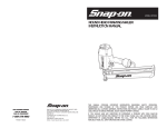
MODEL #870011
CLIPPED HEAD FRAMING NAILER
INSTRUCTION MANUAL
FOR CUSTOMER SERVICE
PARA EL SERVICIO
PARA EL CONSUMIDOR
1-888-278-8092
Printed in Taiwan
SNAP-ON ® IS A TRADEMARK LICENSED BY SNAP-ON ® CORP.,
U.S.A., WHICH DOES NOT MANUFACTURE OR
DISTRIBUTE THIS PRODUCT. CONSUMER INQUIRES SHOULD BE
DIRECTED TO:
©COPYRIGHT 2007 ALLTRADE TOOLS, LLC.
1431 VIA PLATA
LONG BEACH, CA 90810-1462 USA
870011 – Clipped Head Air Nailer _Rev 10/4/07
THIS MANUAL CONTAINS IMPORTANT INFORMATION REGARDING SAFETY, OPERATION,
MAINTENANCE AND STORAGE OF THIS PRODUCT. BEFORE USE, READ CAREFULLY AND
UNDERSTAND ALL CAUTIONS, WARNINGS, INSTRUCTIONS AND PRODUCT LABELS. FAILURE TO DO SO
COULD RESULT IN SERIOUS PERSONAL INJURY AND/OR PROPERTY DAMAGE.
IF YOU SHOULD HAVE ANY QUESTIONS OR EXPERIENCE A PROBLEM WITH YOUR SNAP-ON
PRODUCT, DO NOT RETURN THIS PRODUCT TO THE STORE. PLEASE CALL OUR CUSTOMER SERVICE
DEPARTMENT AT 1-888-278-8092. BEFORE YOU CALL, HAVE THE FOLLOWING INFORMATION
AVAILABLE: MODEL No., DATE PURCHASED AND STORE LOCATION.
TABLE OF CONTENTS
CONGRATULATIONS! . . . . . . . . . . . . . . . . . . . . . . . . . . . . . . . . . . . . . . . . . 2
GENERAL SAFETY RULES . . . . . . . . . . . . . . . . . . . . . . . . . . . . . . . . . . 2
RECOGNIZE SAFETY SYMBOLS, WORDS AND LABELS . . . . . . . . 2-3
IMPORTANT INFORMATION ABOUT THIS MANUAL . . . . . . . . . . . 4
SAFETY WARNINGS AND PRECAUTIONS . . . . . . . . . . . . . . . . . . . 4-7
FUNCTIONAL DESCRIPTION . . . . . . . . . . . . . . . . . . . . . . . . . . . . . . . . . 7-9
COMPONENT INSTALLATION . . . . . . . . . . . . . . . . . . . . . . . . . . . . . 8-9
OPERATING THE CLIPPED HEAD NAILER . . . . . . . . . . . . . . . . . . . . . . 9-13
SELECT TRIGGER ACTUATION MODE . . . . . . . . . . . . . . . . . . . . . . 9-11
ADJUSTING DEPTH OF NAILING . . . . . . . . . . . . . . . . . . . . . . . . . . 11-12
USING THE HOOK . . . . . . . . . . . . . . . . . . . . . . . . . . . . . . . . . . . . . 12
LOADING NAILS INTO THE AIR NAILER . . . . . . . . . . . . . . . . . . . . 12
USING THE NO-MAR NOSEPIECE . . . . . . . . . . . . . . . . . . . . . . . . . 13
REQUIRED DAILY PREPARATION . . . . . . . . . . . . . . . . . . . . . . . . . . . . . 13-14
USING THE AIR NAILER . . . . . . . . . . . . . . . . . . . . . . . . . . . . . . . . . . . . 14-16
LOCKING AND UNLOCKING THE TRIGGER . . . . . . . . . . . . . . . . . . 15
CHANGING DIRECTION OF EXHAUST AIR . . . . . . . . . . . . . . . . . . . 15
CLEARING JAMS . . . . . . . . . . . . . . . . . . . . . . . . . . . . . . . . . . . . . . 16
MAINTENANCE . . . . . . . . . . . . . . . . . . . . . . . . . . . . . . . . . . . . . . . . . . . 16-17
MANDATORY MAINTENANCE . . . . . . . . . . . . . . . . . . . . . . . . . . . . . . . 18
TROUBLESHOOTING . . . . . . . . . . . . . . . . . . . . . . . . . . . . . . . . . . . . . . . 18-19
PARTS DIAGRAM . . . . . . . . . . . . . . . . . . . . . . . . . . . . . . . . . . . . . . . . . 20-21
PARTS LIST . . . . . . . . . . . . . . . . . . . . . . . . . . . . . . . . . . . . . . . . . . . . . 22-25
SPECIFICATIONS . . . . . . . . . . . . . . . . . . . . . . . . . . . . . . . . . . . . . . . . . . 25
1 YEAR LIMITED WARRANTY . . . . . . . . . . . . . . . . . . . . . . . . . . . . . . . . 26-28
CONGRATULATIONS!
Thanks for choosing this product. Our aim is to provide you with the highest quality products, and we want you to be totally satisfied with your product and our Customer Service.
If any help or advice is needed, please contact us at 1-888-278-8092. When properly
cared for, this product will give you many years of satisfaction.
GENERAL SAFETY RULES
READ AND FOLLOW ALL INSTRUCTIONS. Failure to follow all instructions in this manual may result in severe personal injury or death.
Keep this manual and refer to it for Safety Instructions, Operating Procedures,
and Warranty.
SAVE THESE INSTRUCTIONS FOR FUTURE REFERENCE.
RECOGNIZE SAFETY SYMBOLS, WORDS AND LABELS
The safety instructions provided in this manual are not intended to cover all possible
conditions and practices that may occur when operating, maintaining and cleaning
power tools.
Always use common sense and pay particular attention to all the DANGER,
WARNING, CAUTION and NOTE statements of this manual.
This is the safety alert symbol. It is used to alert
you to potential personal injury hazards. Obey all
safety messages that follow this symbol to avoid
possible injury or death.
DANGER indicates an imminently hazardous
situation which, if not avoided, will result in death
or serious injury.
WARNING indicates a potentially hazardous
situation which, if not avoided, could result in
death or serious injury.
CAUTION indicates a potentially hazardous
situation which, if not avoided, may result in
minor or moderate injury.
1
2
CAUTION used without the safety alert symbol
indicates a potentially hazardous situation which,
if not avoided, may result in property damage.
NOTE provides additional information that is useful
for proper use and maintenance of this tool. If a
NOTE is indicated make sure it is fully understood.
IMPORTANT INFORMATION ABOUT THIS MANUAL
Improper maintenance and operation are responsible for the majority of accidents
involving clipped head nailers. The largest portion of these could be prevented by
recognizing the basic safety rules and precautions. Most accidents can be avoided
if the operator recognizes a potentially hazardous situation before it happens and by
observing appropriate safety rules and procedures as outlined in this manual.
Basic safety precautions are outlined in the SAFETY portion of this manual and
throughout text in this manual where a potential hazard might occur.
In addition to SAFETY ALERTS listed above, there could also be numerous symbols
alerting the operator that specific safety equipment is required to safely operate this
tool. Learn these SAFETY SYMBOLS as well as the SAFETY ALERTS to prevent
injury to the operator and to bystanders.
READ OPERATING INSTRUCTIONS: Read and understand tool labels,
safety warnings and precautions in this manual before operating the tool.
Failure to follow WARNINGS could result in serious injury or even death
to the operator or bystanders.
Hazards that MUST be avoided to prevent serious injury follow headers marked
DANGER or WARNING. These same precautions are placed as labels on the tool
itself.
NEVER use this nailer for applications that are NOT specified in this manual.
SAFETY WARNINGS AND PRECAUTIONS
WEAR APPROVED EYE PROTECTION: Safety glasses must conform to
the requirements of American National Standards Institute (ANSI) Z87.1
and provide protection against flying particles from both front and side.
Do not operate clipped head nailer anywhere fastener may contact hidden
electrical wiring. Contact with a “live” wire will make all metal parts of the
clipped head nailer “live.” This can result in severe electrical shock, severe
burns or death to the operator. Contact a qualified electrical contractor to
ensure a safe working environment exists.
WEAR HEARING PROTECTORS: Hearing protectors should be worn to
protect the ears from loud exhaust noise produced by the air tools.
Be aware of conduits or gas pipes. Striking a gas pipe could result in an explosion causing serious injuries or even death to the operator or bystanders.
USE ONLY CLEAN, DRY COMPRESSED AIR: Never use oxygen, combustible gases and any other bottled gas to operate air tools. Using these
other sources can cause the air tool to explode.
NEVER POINT THE AIR NAILER AT YOURSELF OR OTHERS: Fasteners
are under extreme pressure and can cause severe injury or even death if
misused.
DO NOT EXCEED 120 psi (8.43 kg/cm2G). Using excessive pressure
from the power source can cause the clipped head nailer to explode
resulting in severe injury or even death to the operator or bystanders.
3
Be aware of what is behind the work piece. A fastener could travel through the
work piece and out the other side, striking a bystander resulting in serious
injury or even death.
Do not operate the clipped head nailer in the presence of flammable liquids, such
as gasoline, thinner, paint, or adhesives, gases or dust. Sparks created by the tool
can cause flammable materials to ignite or explode. Failure to comply with this warning could result in serious injury or even death to the operator.
Keep bystanders, children and visitors away from area where clipped head
nailer is being used. Distractions can result in severe injury or even death to
anyone who inadvertently gets in the way of nailing operations.
Do not use oxygen, combustible or bottled gases (such as carbon
dioxide or nitrogen) as a power source for the clipped head nailer.
Use only compressed air from a source as outlined in this manual.
The tool will explode resulting in severe injury or even death to the operator and
bystanders.
Do not connect clipped head nailer to an air source capable of
generating more than 200 psi (14.06 kg/cm2 G). Over-pressurizing
the clipped head nailer will result in bursting, abnormal operation or
breakage of the tool. Use only clean, dry, regulated compressed air
at levels specified on the tool. Failure to comply can cause severe injury or
death to the operator or bystanders.
Do not attempt to fasten the trigger in the “ON” position. This could lead to
an accidental discharge of the clipped head nailer. Do not operate the clipped
head nailer if any portion of the tool’s operating controls are inoperable, disconnected, altered in any way or not in proper working order. Failure to comply with
this warning could result in serious injury or even death to the operator or other
bystanders.
All air compressors must comply with the requirements of ANSI
b19.3. Pressure regulators must be used to limit air pressure where
air supply pressure exceeds the tool’s rated operating pressure.
Do not carry the clipped head nailer with a finger on the trigger. This could
lead to an accidental discharge of the clipped head nailer. Do not press the trigger of the clipped head nailer unless it is pressed firmly against the work piece.
Do not point the clipped head nailer at yourself or in the direction of another
person. Failure to comply with this warning could result in serious injury or
even death to the operator or other bystanders.
Do not tamper with the work piece contact. The work piece contact prevents
accidental discharge of the clipped head nailer and should never be removed or
compromised in any way. Failure to comply with this warning could result in
serious injury or even death to the operator or other bystanders.
Always disconnect air hose and remove any remaining nails:
1. When clipped head nailer is left unattended.
2. Before performing any maintenance or repair on the clipped head nailer.
3. Before attempting to clear a jam in the clipped head nailer.
4. Before moving the clipped head nailer to a new location.
Always check the overall condition of the clipped head nailer before using.
Check for and tighten any loose screws. Ensure all safety systems are in working condition before using the clipped head nailer. The clipped head nailer must
not operate if only the trigger is pulled or if only the work piece contact is
pressed against the work piece. The clipped head nailer must only be used if
both the trigger and work piece contact work at the same time.
5
Always use hearing protection to protect your ears against
hearing loss due to exhaust noise. Always wear proper safety glasses to prevent injuries to the eyes from fragments of
the work piece, defective nails or other debris caused by using the clipped
head nailer. All safety glasses must have side shields and should conform to
the requirements of the American National Standards Institute (ANSI) z87.1.
Failure to comply with this warning could lead to serious or permanent damage
to the ears as well as serious damage or permanent blindness in the eyes.
Never carry the clipped head nailer by the air hose. A sudden disconnection
of the air hose could cause the clipped head nailer to remain charged and an
accidental firing could occur. Failure to comply with this warning could lead to
serious injury to the operator or bystanders.
Always disconnect the power source and ensure the tool is not charged
before loading fasteners. Failure to comply with this warning could cause
severe injury or death to the operator, bystanders and severe damage to the
clipped head nailer.
Never use a non-relieving air coupler with the clipped head nailer. Always
use couplers that release any built-up charge in the clipped head nailer’s firing
mechanism. A non-relieving air coupler can allow the clipped head nailer to discharge a fastener while the tool is disconnected from the power source. Failure
to comply with this warning can result in serious or permanent injury or even
death to the operator or to bystanders.
Do not drive nails on top of other nails. Do not operate the clipped head nailer at too steep of an angle. Nails can ricochet. Failure to comply with this warning can result in serious injury or even death to the operator or bystanders.
Do not modify the clipped head nailer in any way. Unauthorized alterations
can jeopardize safety in the tool’s operation. Failure to follow this precaution can
result in serious injury or even death to the operator or bystanders.
On rooftops and other high locations, always move forward as you use the
clipped head nailer. You can easily loose your footing if moving backwards.
When nailing against a perpendicular surface, nail from the top down. This
causes less fatigue and reduces the chances of accidents.
Ensure the work area is sufficiently illuminated to operate power tools. The
work area should be clear and free of litter.
6
COMPONENT INSTALLATION
Thoroughly clean and maintain the clipped head nailer after every use.
Lubricate moving parts to prevent rust and minimize friction-related wear. Wipe
down the entire tool and remove all dust from the moving parts. Properly store
the clipped head nailer in a suitable case to keep it ready for the next job.
All maintenance and repairs should be performed by an authorized repair
facility. Call 1-888-278-8092 to obtain a list of repair facilities in your area or
to make arrangements to return the tool for service.
FUNCTIONAL DESCRIPTION
Never use a non-relieving air coupler with the clipped
head nailer. Always use couplers that release any built-up charge in the clipped
head nailer’s firing mechanism. A non-relieving air coupler can allow the clipped
head nailer to discharge a fastener while the tool is disconnected from the
power source. Failure to comply with this warning can result in serious or permanent injury or even death to the operator or to bystanders.
When selecting an air compressor, it must comply with the requirements of the
American National Safety Institute - ANSI B19.3.
Choose an air compressor that can supply more than the required air pressure to
ensure optimum efficiency. Always use clean, dry compressed air with a maximum
pressure of 200 psi. Use a pressure regulator and set the pressure between 70-120
PSIG (5.0- 8.5 kg/cm 2 G). Before each use, check the pressure regulator to ensure
it is functioning within the proper pressure range.
Using an air pressure of more than 120 psi can
cause the clipped head nailer to malfunction or possibly explode
causing severe injury or property damage.
SELECTING A PROPER AIR HOSE
Use an air hose with the largest diameter and shortest length possible to ensure
continuous, efficient nailing operations. Using an air pressure of 70 psi (5.0
kg/cm2G), an air hose with an inside diameter of 1/4" (6.5 mm) or greater and a hose
length of less than 6.6 ft (20 m), it is recommended that a 0.5 second interval be
allowed between each nailing. Air supply hoses shall have a minimum working pressure of 150 psi (10.7 kg/cm2G) or 150% of the maximum pressure produced by the
compressor or whichever is higher.
CONTROLS AND COMPONENTS:
1. Exhaust Cover
2. Trigger Lock
3. Trigger
4. Spring Lever
5. No-mar Nosepiece
6. Pusher
7. Air Inlet
8. Hanging Hook
9. Magazine Inlet
10. Nail Stop
ACCESSORIES:
11. Safety Glasses
12. Lubricant
13. Hex Wrenches (2)
Low air output by the compressor or a longer hose with
a smaller inside diameter in relation to the nailing frequency may decrease
the driving capability of the air nailer.
SELECTING A QUICK DISCONNECT
1. Remove the plastic protective plug
from the tool’s air inlet.
2. Insert a 1/4" NPT male quick
disconnect into the air inlet. Install
the female portion to the air hose.
7
8
To improve the connection between the quick disconnect and air nailer, and to help
prevent oxidation, apply PTFE tape or joint compound to the connector threads
before insertion.
OPERATION IN SINGLE SEQUENTIAL ACTUATION MODE
To select the Single Sequential Actuation Mode (see
Figure 1):
3. Snap the air hose onto the quick disconnect on the air nailer. Check for air
leaks.
1. Press and hold the red Actuation Selector embedded
in the trigger.
LUBRICATION
To ensure maximum performance, it is recommended to install an air set (oiler, regulator, and air filter) as close as possible to the air nailer. Adjust the oiler so that
approximately one drop of oil will be released for every 50 nails.
If an air set is not used or is unavailable, oil the tool using pneumatic tool oil by placing 2 or 3 drops into the air inlet. This should be done before and after use. For
proper lubrication, the tool must be fired several times after the oil is introduced to
the filter.
OPERATING THE CLIPPED HEAD NAILER
Always use hearing protection to protect your ears against
hearing loss due to exhaust noise. Always wear proper safety glasses to prevent injuries to the eyes from fragments of
the work piece, defective nails or other debris caused by using the clipped
head nailer. All safety glasses must have side shields and should conform to
the requirements of the American National Standards Institute (ANSI) z87.1.
Failure to comply with this warning could lead to serious or permanent damage
to the ears as well as serious damage or permanent blindness in the eyes.
Always disconnect the air hose before making adjustments or checking the
functionality of the air nailer.
2. Rotate Actuation Selector down to the Single
Sequential Actuation (T).
3. Release Actuation Selector, ensuring locking tab is
fully seated in the slot.
Figure 1
Ensure selector has locked into position. Ensure
actuation process is fully understood before attempting to use clipped head
nailer.
TO USE THE CLIPPED HEAD NAILER IN SINGLE SEQUENTIAL
ACTUATION MODE:
1. Firmly grip clipped head nailer handle.
2. Position clipped head nailer work piece
contact on work piece surface.
3. Push clipped head nailer against work
piece compressing work piece contact.
4. Pull trigger on clipped head nailer to
drive nail. The clipped head nailer will
recoil away from the work piece as nail
is driven.
5. Remove finger from trigger and lift
clipped head nailer away from surface
of work piece.
SELECT TRIGGER ACTUATION MODE
The clipped head nailer is equipped with a selectable trigger. This allows the selection of Single Sequential Actuation Mode or Contact Actuation Mode.
OPERATION IN CONTACT ACTUATION MODE
When using contact actuation mode, be careful of unintentional double fires resulting from tool recoil. Unwanted fasteners may be
driven if the work piece contact is allowed to accidentally re-contact the work
piece.
9
10
To select Contact Sequential Actuation Mode (see Figure 2):
Always disconnect the clipped head nailer before making any adjustments to the nail depth setting.
1. Press and hold Actuation Selector embedded in the
trigger.
2. Rotate Actuation Selector up to the Contact
Sequential Actuation (TTT).
3. Release Actuation Selector, ensuring locking tab is
fully seated in the slot.
USING THE HOOK
Figure 2
Ensure selector has locked into position. Ensure
actuation process is fully understood before attempting to use clipped head
nailer.
Always disconnect the air hose before hanging the clipped head nailer with
the hook.
NEVER hook the clipped head nailer in a high location or on an unstable platform.
LOADING NAILS INTO THE AIR NAILER
TO USE THE CLIPPED HEAD NAILER IN CONTACT ACTUATION MODE:
1. Firmly grip clipped head nailer handle.
2. Pull and hold the clipped head nailer trigger.
3. Push clipped head nailer against work piece compressing work piece contact.
4. The clipped head nailer will drive nail upon contact. The clipped head nailer will
recoil away from the work piece as nail is driven.
Always disconnect the air hose from the clipped head nailer before adding
or removing nails.
NEVER use deformed nails or nail strip. Failure to observe this precaution
can result in poor nail feeding and/or jams in the feeding mechanism.
To load nails in clipped head nailer, slide nails through magazine inlet in back of magazine. Pull pusher back until it is behind nail strip, then release pusher.
ADJUSTING DEPTH OF NAILING
Be aware of material thickness when using nailer. A protruding nail may cause injury.
Adjust the depth of nailing by loosening the two hex
nuts (figure 3). Move nosepiece down for a shallower nail depth or up for a deeper nail depth. Once
nosepiece is adjusted, tighten hex screws. To
increase the depth of the nails when the nosepiece
is already set to its lowest setting, increase the air
pressure. To decrease the depth of nails when the
nosepiece is already set to its highest setting,
decrease the air pressure.
Figure 4
To remove nails from clipped head nailer, pull slightly back on pusher and depress
spring lever (Figure 4). Allow pusher to pass over nail strip and move strip to back
of magazine. Depress the nail stop allowing nail strip to be removed from magazine
inlet.
Figure 3
11
12
USING THE NO-MAR NOSEPIECE
Always disconnect the air hose before attaching the
no-mar nosepiece.
In order to prevent the surface of the work piece from
being scratched or damaged, use the no-mar nosepiece. Install no-mar nosepiece by pressing it into
place on the nose frame. See Figure 5.
Store the no-mar nosepiece in place when not being
used.
6. Select Single Sequential Actuation Operation. Check for leaks. Without pulling
the trigger, press the work piece contact against the work piece. The tool
MUST NOT operate. Holding the tool away from the work piece, pull trigger
and hold for 5 seconds. The tool MUST NOT operate. Repeat steps several
times. Without pulling trigger, press nailer against work piece and pull trigger.
The tool MUST operate. Release trigger. Driver MUST move up.
7. Select Contact Actuation Operation. Holding nailer away from work piece, pull
trigger. The tool MUST NOT operate. While still pulling trigger, press the nailer
against work piece. The tool MUST operate.
8. If Steps 1 through 7 function properly, prepare the tool for use. Select operation mode and load fasteners.
9. Set the required depth of drive.
Figure 5
10.Repeat these steps daily. Test again if the nailer is dropped, jammed, etc.
Never use a non-relieving air coupler with the clipped
head nailer. Always use couplers that release any built-up charge in the
clipped head nailer’s firing mechanism. A non-relieving air coupler can
allow the clipped head nailer to discharge a fastener while the tool is disconnected from the power source. Failure to comply with this warning can
result in serious or permanent injury or even death to the operator or to
bystanders.
When the air hose is disconnected, the pressure reservoir in the air nailer will
discharge removing any built-up air inside the tool.
REQUIRED DAILY PREPARATION
The following steps should be performed on a daily basis to ensure the clipped head
nailer is operating correctly:
1. Disconnect air supply from nailer and remove fastener strip.
2. Check all screws, nuts and pins and ensure all are tight.
3. Press the pusher release button and slide back the pusher assembly
(Overriding the dry fire lockout). Press the work piece contact against a work
piece ensuring smooth movement.
USING THE AIR NAILER
To drive a nail, place the work piece
contact of the clipped head nailer
against the work piece and pull the
trigger. See Figure 6.
To avoid any unexpected nailings,
perform the operation as follows:
1. Avoid placing the work piece contact
against the work piece with excessive
force.
2. Pull the trigger fully and hold it in the
fired position for 1 to 2 seconds
before releasing the trigger. This will
give the clipped head nailer time to
completely expend the previous nail
and build enough pressure for the next nail.
4. With work piece contact against the work piece, pull trigger. The trigger must
operate smoothly.
5. Connect air supply and set regulator for 70 psi. DO NOT load a fastener strip.
13
14
Figure 6
CLEARING JAMS
DO NOT hold the trigger in a half-pulled position. This
could cause an unexpected nailing to occur if the work piece contact is permitted to re-contact the work piece. Failure to comply could result in damage to
work piece.
LOCKING AND UNLOCKING THE TRIGGER
Always move lever to the locked position immediately
after using the nailer to prevent unintended firing of fastener.
Typically, jams are caused when a fastener or a fastener fragment becomes wedged
between the driver blade and nail guide. Using the wrong fastener can also cause jams.
TO CLEAR A JAM:
1. Disconnect the air supply and
remove the fastener strip. Leave the
pusher assembly open.
2. Loosen hex screws from back of
magazine and pull magazine back.
See Figure 9.
The clipped head nailer is equipped with a trigger
lock to prevent operation of the tool when not
actively being used. To lock trigger, move trigger
lock lever up to the locked position. To unlock trigger in preparation for use, move the trigger lock
lever down to the unlocked position (Figure 7).
Figure 9
3. Remove jammed fastener.
4. Slide magazine back in position and
refasten hex screws (Figure 10).
Figure 7
Figure 10
MAINTENANCE
CHANGING DIRECTION OF EXHAUST AIR
STORAGE OF NAILS
Always handle nail strips and their box very carefully. If the nail strips have been mishandled, they may be out of shape or have breaks in the connecting strips. This will
cause the nails to feed poorly and possibly result in misfiring or jams in the air nailer.
The direction of exhaust air on the air nailer can be
directed 360˚ degrees by placing hand on exhaust
cover and turning. See Figure 8.
Avoid storing nails in a very humid or hot environment or place in direct sunlight.
OVERALL MAINTENANCE OF AIR NAILER
Figure 8
Always disconnect the air hose from clipped head nailer before attempting any type of maintenance or visual inspection of tool.
15
16
Always visually inspect clipped head nailer before every use. Check on the overall
condition and for any loose screws. Tighten any screws that have come loose. See
Figure 11.
MANDATORY MAINTENANCE
All maintenance and repairs should be performed by an
authorized repair facility. Call 1-888-278-8092 to obtain a list of repair facilities in your area or to make arrangements to return the tool for service.
Visually inspect the work piece contact and
trigger to ensure there is free movement. See
Figure 12.
When the tool is not going to be used for an
extended period, wipe off all dust and debris
that have collected on it. Tighten all loose
screws. Lubricate the firing mechanism with
pneumatic tool oil. See page 9 for
Lubrication.
ACTION
Figure 11
Store the clipped head nailer in a safe location or in suitable carrying case. It is recommended that the air nailer be secured in a
locked location to prevent unauthorized
usage.
Avoid exposure to direct sunlight and/or
locations with high humidity and heat.
REASON
OPERATION
Clean magazine and
feeder mechanism.
Prevents clipped head
nailer from jamming.
Use compressed air and
clean daily.
Inspect and ensure work
piece contact operates
properly.
Ensures operator safety
and keeps clipped head
nailer working efficiently.
Use compressed air and
clean daily.
Lubricate clipped head
nailer after every use
using pneumatic tool oil.
Extends life of clipped
head nailer.
Apply 2 – 3 drops of
pneumatic tool oil to
clipped head nailer air
inlet after every use.
TROUBLESHOOTING
Figure 12
Remove the clipped head nailer from use and schedule
to have it repaired at an authorized repair facility if the work piece contact is
binding or not moving freely. Do not attempt to repair the clipped head nailer. Failure to comply can result in malfunction of the tool and severe injury
to the operator or any bystanders.
17
Most minor problems can be resolved quickly and easily using the troubleshooting
table below. For problems that cannot be solved, contact Customer Service (toll
free) at 1-888-278-8092.
PROBLEM
POSSIBLE CAUSE
SOLUTION
Nailer operates, but no
nail is driven.
Check for jammed nail.
Ribbon spring weakened
or damaged.
Inspect nail feeder
mechanism.
Ensure correct nails are
being used.
Clear jammed nail.
Replace ribbon spring.
Clean and lubricate nail
feeder.
Use ONLY recommended nails.
18
PROBLEM
POSSIBLE CAUSE
SOLUTION
Weak drive. Slow to
cycle between nailings.
Ensure proper air pressure is being used.
Inspect for worn driver
blade.
Inspect piston O-ring for
wear or damage.
Increase air pressure,
Do not exceed 120 psig
(8.3 bars, 8.5 kg/cm2)
Contact Customer
Service.
Nails driven too deep.
Check air pressure.
Reduce air pressure.
Clipped head nailer
feeds intermittently or
skips nails.
Ensure correct nails are
being used.
Inspect nail feeder
mechanism.
Ribbon spring weakened
or damaged.
Piston O-ring damaged
or worn
Nail feeder worn or
damaged.
Use ONLY recommended nails.
Clean and lubricate nail
feeder.
Replace ribbon spring.
Use recommended
pneumatic tool oil.
Contact Customer
Service.
Replace nail feeder.
Nails jam or driven nail
is bent.
Ensure correct nails are
being used.
Inspect for worn driver
blade.
Nail feeder worn or
damaged.
Use ONLY recommended nails.
Contact Customer
Service.
Replace nail feeder.
Drives nails properly
during normal nailing
operations, but fails to
drive nails fully at faster
operating speeds.
Check inside diameter of
air hose.
Switch to air hose with
larger inside diameter.
19
PARTS DIAGRAM
20
PARTS DIAGRAM
PARTS LIST
ITEM NO.
21
PART NO.
DESCRIPTION
1
K0300-4011
Top Cap Set
2
A0000-0421
Nylon Screw M6*18
3
A0005-1071
Washer
4
A0304-0521
Exhaust Cover
5
A0000-0171
Screw M6*30
6
A0005-0541
Washer 12.5*1.6T
7
A0200-0811
O-Ring 11.8*1.5
8
A0203-0111
Muffler
9
K0300-4021
Top Cap & Screw Set
10
A0003-0331
Screw
11
A0301-1641
Cap, Top
12
A0317-0001
Wear Ring
13
A0100-1971
Spring
14
K0300-2741
Firing Valve Set
15
A0200-2612
O-Ring 39.4*3.2
16
A0200-3211
O-Ring 59.4*3.1
17
A0308-0491
Firing Valve
18
A0313-0281
Seal Firing Valve
19
A0005-0551
Washer Support
20
A0313-0121
Piston Retainer
21
K0600-3991
Piston Unit
22
A0200-1962
O-Ring 47.3*3.5
23
K0600-3981
Piston Set
24
A0205-0411
Gasket
22
ITEM NO.
PART NO.
O-Ring 58*2.5
50
A0401-2031
Body
A0200-1952
O-Ring 57.5*3.3
51
A0004-0021
Nylon Nut M5
27
A0303-0811
Cylinder
52
K0500-1501
Trigger Set
28
A0800-0781
Spacer
53
A0011-0201
Spring Pin 3*30
29
A0200-2002
O-Ring 85*3.5
54
A0009-0011
Steel Ball
30
A0311-0351
Sleeve Hold Down
55
A0100-1961
Spring
31
A0305-0131
Collar
56
B0000-0351
Lock Pin Set
32
K0500-0901
Trigger Valve Set
57
A0000-0411
Nylon Screw M5*20
33
A0313-0651
Main Body Bumper
58
A0712-1191
Catch Cover
34
A0712-1181
Release Guide
59
A0201-0122
Bushing
35
A0011-0091
Spring Pin 3*20
60
A0711-2021
Lower Safety B
36
A0005-0131
E-Ring 4
61
A0711-2001
Lower Safety A
37
A0719-1211
Hook Fixer
62
A0204-1081
No Mar Pad
38
A0000-1791
Nylon Screw M5*28
63
A0106-0101
Spring Clip
39
A0005-0531
Washer 14*1T
64
A0713-0881
Guide Body
40
A0100-1051
Outlet Spring
65
A0100-2151
Spring
41
A0011-0071
Spring Pin 3*16
66
A0000-0891
Screw M8*25
42
A0000-0351
Screw M3*8
67
A0713-0341
Feeder Shoe Stop
43
A0706-1711
Support
68
A0309-0731
Bumper
44
A0316-0341
Hook
69
A0200-0791
O-Ring 63.9*2.5
45
A0204-1671
Grip
70
A0200-1101
O-Ring 7*2
46
A0306-1201
Tail Cover
71
K1100-2421
Magazine Set
47
A0011-0161
Spring Pin 3*24
72
A0706-1371
Support
48
A0203-0191
Filter
73
A0708-0392
Steel Bar
49
A0200-3011
O-Ring 50*3
74
A0713-0352
Insert
ITEM NO.
PART NO.
25
A0200-3221
26
DESCRIPTION
23
DESCRIPTION
24
ITEM NO.
PART NO.
DESCRIPTION
75
A0000-0681
BHSC Screw M5*10
76
A0000-0061
Screw M5*12
77
K0700-4741
Magazine Set
78
A0003-0221
Rivet
79
A0718-0561
Magazine Cover
80
A0105-0191
Nail Detainer
81
A0701-2431
Rail Magazine
82
K0700-4771
Pusher Assembly
83
A0102-0071
Spring
84
A0703-0151
Roller, Negator Spring
85
A0005-0311
Pin Retainer 5.5*2
86
A0707-1741
Feeder Clip
87
A0100-1081
Spring
88
K0700-4751
Pusher Set
89
A0006-1351
Pin
SPECIFICATIONS
MODEL NUMBER
870011
AIR PRESSURE
70-120 PSIG (5.0- 8.5 kg/cm 2 G
NAIL LENGTH
2" (50.8 mm) - 3 1/2" (88.9 mm)
COLLATION ANGLE
30-34°
MINIMUM HOSE
DIAMETER
1/4" (6.5 mm)
NET WEIGHT
7.2 LBS. (3.2 KG)
25
1 YEAR LIMITED WARRANTY
Express and Exclusive Limited Warranty to Original Retail Buyer
Alltrade Tools LLC (hereinafter "Alltrade") expressly warrants to the original retail
purchaser of the accompanying SNAP-ON™ portable air tool and no one else all
parts of the product (except those parts referred to below which are specifically
excluded from such warranty (see Exclusions) to be free from defects in materials
and workmanship for a period of one year from the original date of purchase.
The date of purchase shall be the date of shipment to the original purchaser, or the
date the original purchaser took possession, custody, or control of the product,
whichever occurred first. This warranty shall be null and void if the product or any
component thereof is modified or altered. This warranty does not apply to any other
product and/or component thereof manufactured or distributed by Alltrade, and
does not apply to products and/or components thereof designed, manufactured
and/or assembled by others, for which Alltrade makes no warranties whatsoever.
THERE ARE NO WARRANTIES, WHICH EXTEND BEYOND THE DESCRIPTION ON
THE FACE HEREOF.
WARRANTY PERFORMANCE
By purchasing this product, purchaser expressly acknowledges and agrees that
their sole and exclusive remedy under this warranty shall be strictly limited to the
repair or replacement of any covered nonconforming items or parts thereof provided that any such nonconforming item and/or part is promptly returned to an authorized Service Center within the applicable warranty period, with a written request by
purchaser to repair and/or replace the nonconforming item and/or part. We recommend that you keep the original product packaging in the event you need to ship the
unit. We suggest the package be insured against loss or in transit damage. When
sending your product, include your name, address, phone number, e-mail address,
dated proof of purchase (or copy) and a statement about the nature of the problem.
Warranty coverage is conditioned upon purchaser furnishing Alltrade with adequate
written proof that they are the original purchaser and of the original purchase date.
Parts returned, freight prepaid and insured, will be inspected and, at Alltrade's
option, repaired and/or replaced free of charge if it is found to be defective and subject to warranty. Alltrade retains the sole discretion to determine whether any item
or part is nonconforming and, if so, whether the item and/or part will be repaired
and/or replaced. If the unit is repaired, new or reconditioned replacement parts may
be used. If Alltrade chooses to replace the product, it may replace it with a new or
reconditioned of the same or comparable design. The repaired or replaced unit will
be warranted under the terms of the remainder of the one year warranty period; covered defective parts not subject to normal wear and tear or other exclusions will be
repaired or replaced, at Alltrade's option. During the warranty period, Alltrade will
be responsible for the return shipping charges. Alltrade's repair and/or replacement
of any nonconforming item and/or part thereof shall constitute fulfillment of all obli-
26
gations to the purchaser. Alltrade shall not be responsible or liable for any expense,
including freight charges, or repairs made outside Alltrade's facility or an Alltrade
designated service, unless expressly agreed to by Alltrade in writing. Under no circumstances shall Alltrade bear any responsibility for loss of the unit, loss of time or
rental, inconvenience, commercial loss, or consequential damages.
For the location of an Authorized Service Center nearest you, please call customer
service at 1-888-278-8092.
EXCLUSIONS
Air nailers and staplers need periodic maintenance to remain in proper operating
condition. Normal wear parts (o-rings and driver blades) shall be warranted to the
original purchaser to be free from defects in materials and workmanship for a period of 90 days from the original date of purchase.
This warranty does not cover parts damaged due to normal wear, abnormal conditions, misapplication, misuse, abuse, accidents, operation, improper storage, or
freight damage. Parts damaged or worn by operation in dusty environments are not
warranted. Failure to follow recommended operating and maintenance procedures
also voids warranty.
DAMAGE TO THE PRODUCT RESULTING FROM TAMPERING, ACCIDENT, ABUSE,
NEGLIGENCE, FAILURE TO FOLLOW INSTRUCTIONS, UNAUTHORIZED REPAIRS
OR ALTERATIONS, DAMAGE WHILE IN TRANSIT TO OUR SERVICE FACILITY, USE
OF UNAPPROVED OR IMPROPER ATTACHMENTS OR ACCESSORIES, OR OTHER
CAUSES UNRELATED TO PROBLEMS WITH MATERIAL OR WORKMANSHIP ARE
NOT COVERED BY THIS WARRANTY.
Alltrade will not be liable for the following: labor charges, loss or damage resulting
from improper operation, maintenance or repairs made by other persons; pre-delivery services such as assembly, oil and lubricants, and adjustment; maintenance
services that are normally required to maintain the product.
The use of other than genuine Snap-On™ Repair Parts will VOID the warranty.
WARRANTY DISCLAIMERS
EXCLUSION AND DISCLAIMER OF ALL OTHER EXPRESS WARRANTIES, GUARANTIES AND/OR REPRESENTATIONS, EXCEPT FOR THE LIMITED WARRANTY
PROVIDED HEREIN, ALL OTHER EXPRESS WARRANTIES, GUARANTIES, AND/OR
REPRESENTATIONS BY ALLTRADE AND OR ITS REPRESENTATIVE(S) REGARDING
THE DESIGN, MANUFACTURE, PURCHASE, USE AND/OR OPERATION OF THE
PRODUCT OR ANY COMPONENT THEREOF SOLD HEREUNDER, REGARDLESS OF
WHETHER ANY SUCH WARRANTY, GUARANTY AND/OR REPRESENTATION,
WRITTEN OR ORAL, ARISES BY OPERATION OF LAW AND/OR EQUITY AND/OR BY
ANY ACT OR OMISSION OF ALLTRADE AND/OR ITS REPRESENTATIVE(S), OR THE
BUYER, ARE HEREBY EXPRESSLY EXCLUDED AND DISCLAIMED BY ALLTRADE
AND/OR ITS REPRESENTATIVES. PURCHASER KNOWINGLY AND WILLINGLY
27
WAIVES ANY AND ALL SUCH WARRANTIES AND RIGHTS, CLAIMS AND/OR
CAUSE OF ACTION ARISING THEREFROM OR BASED THEREON. PURCHASER'S
SOLE AND EXCLUSIVE REMEDY IS AS STATED ABOVE.
EXCLUSION AND DISCLAIMER OF ALL IMPLIED WARRANTIES, INCLUDING THE
IMPLIED WARRANTIES OF MERCHANTABILITY AND FITNESS FOR A PARTICULAR
PURPOSE. NO WARRANTY, ORAL OR WRITTEN, OTHER THAN THE WARRANTY
LISTED HEREIN IS MADE WITH REGARD TO THIS PRODUCT. ALL WARRANTIES
AND/OR IMPLIED WARRANTIES, GUARANTIES AND/OR REPRESENTATIONS BY
ALLTRADE AND/OR ITS REPRESENTATIVE(S) REGARDING THE DESIGN, MANUFACTURE, PURCHASE, USE AND/OR OPERATION OF THE PRODUCT OR ANY COMPONENT THEREOF SOLD HEREUNDER, REGARDLESS OF WHETHER ANY SUCH
WARRANTY, GUARANTY AND/OR REPRESENTATION, WRITTEN OR ORAL, ARISES
BY OPERATION OF LAW AND/OR EQUITY AND/OR BY ANY ACT OR OMISSION OF
ALLTRADE AND/OR ITS REPRESENTATIVES. PURCHASER KNOWINGLY AND
WILLINGLY WAIVES ANY AND ALL SUCH WARRANTIES AND RIGHTS, CLAIMS
AND/OR CAUSES OF ACTION ARISING THEREFROM OR BASED THEREON.
PURCHASER'S SOLE AND EXCLUSIVE REMEDY IS AS STATED ON PRECEDING
PAGES.
LIMITATIONS OF LIABILITY
IN NO EVENT SHALL ALLTRADE AND/OR ITS REPRESENTATIVE(S) BE LIABLE FOR
INDIRECT, INCIDENTAL, SPECIAL AND/OR CONSEQUENTIAL DAMAGES OF ANY
KIND ARISING OUT OF OR RELATED TO, DIRECTLY OR INDIRECTLY, ANY BREACH
OR PROVISION OF ANY AGREEMENT BETWEEN ALLTRADE AND/OR ITS REPRESENTATIVE(S) AND PURCHASER, AND WARRANTY HEREUNDER, AND/OR THE
EXISTENCE, DESIGN, MANUFACTURE, PURCHASE, USE AND/OR OPERATION OF
ANY ITEM(S) SOLD HEREUNDER EVEN IF ALLTRADE AND/OR ITS REPRESENTATIVE(S) HAS BEEN ADVISED OF THE POSSIBILITY OF ANY SUCH DAMAGES. IN NO
EVENT, WHETHER BECAUSE OF A BREACH OF CONTRACT, WARRANTY, TORT
(INCLUDING NEGLIGENCE) OR OTHERWISE, SHALL ALLTRADE'S AND/OR ITS
REPRESENTATIVE (S) LIABILITY EXCEED THE PRICE OF THE PRODUCT. All LIABILITY CONNECTED WITH THE USE OF THIS PRODUCT SHALL TERMINATE UPON
THE EXPIRATION OF THE WARRANTY PERIODS SPECIFIED ABOVE.
LIMITATIONS ON WARRANTY DISCLAIMERS
Some states do not allow limitations on how long an implied warranty lasts and
some states do not allow the exclusion or limitation of the incidental or consequential damages, so part or all of the above limitations or exclusions may not apply to
you. This warranty gives you specific legal rights, and you may also have other
rights, which vary from state to state.
If your product is not covered by this warranty, please call our Customer Service
Department at 1-888-278-8092 for general repair information, and charges and the
location of your nearest authorized service facility.
28