1
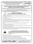
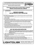
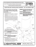
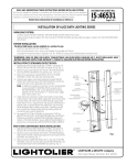
READ AND UNDERSTAND THESE INSTRUCTIONS BEFORE INSTALLING FIXTURE
This fixture is intended for installation in accordance with the National Electrical Code and local regulations.
To assure full compliance with local codes and regulations, check with your local electrical inspector
before installation. To prevent electric shock, turn off electricity at fuse box before proceeding.
Retain these instructions for maintenance reference.
INSTRUCTION SHEET NO.
IS:EMSU
A0200
Page 1 of 3
INSTRUCTION FOR INSTALLATION OF PRE-WIRED COMPACT FLUORESCENT
EMERGENCY LIGHTING DECORATIVE SURFACE UTILITY FIXTURES
WARNING: (RISK OF FIRE) SUPPLY WIRING MUST BE RATED 90˚C. WHEN INSTALLING THE FOLLOWING MODEL NUMBERS ONLY: 5240WH326UE, 5241WH326UE,
5242PB326UE, 5243SA326UE, 5243SB326UE, 5543PB326UE AND 5543WH326UE. MOST DWELLINGS BUILT BEFORE 1985 HAVE SUPPLY WIRE RATED FOR 60˚.
CONSULT A QUALIFIED ELECTRICIAN BEFORE INSTALLATION.
NOTICE: THIS INSTRUCTION SHEET TO BE USED IN CONJUNCTION WITH INSTRUCTIONS
SUPPLIED FOR THE INSTALLATION OF SPECIFIC MODEL BEING INSTALLED.
IMPORTANT SAFEGUARDS
READ AND FOLLOW ALL SAFETY INSTRUCTIONS
WHEN USING ELECTRICAL EQUIPMENT, BASIC SAFETY PRECAUTIONS SHOULD ALWAYS BE FOLLOWED INCLUDING:
1. Turn off AC power before proceeding.
2. Be sure all electrical connections are complete and outlet box is closed before battery connectors on emergency pack
are connected.
3. Do not use outdoors.
4. Do not mount near gas or electrical heaters.
5. Do not attemp to service the battery. A sealed, rechargeable, no maintance battery is used. Do not incinerate or mutilate;
may burst or release toxic materials. Do not short circuit; may cause burns. Battery acid can cause burns to skin and
eyes. If acid is spilled on skin or eyes, flush with fresh water and contact a physician immediately.
6. Equipment should be mounted in locations and at a height where it will not be readily subject to tampering by unauthorized
personnel.
7. The use of accessory equipment is not reccommended by the manufacturer and may cause an unsafe condition.
8. Do not use the equipment for other than intended use.
9. This unit has more than one power supply connection piont. To reduce the risk of electrical shock, disconnect both the
normal and the emergency power supplies before servicing.
10. Before servicing to prevent electrical shock, disconnect the battery connectors on the emergency pack (located on the
end of the emergency pack). Make certain that the switch (if the fixture is switched) and the unswitched lines to the
emergency pack are turned off at the fuse box. Servicing should be performed by qualified personnel only.
INSTALLATION
WARNING: TO PREVENT HIGH VOLTAGE ON THE RED & YELLOW OUTPUT LEADS PRIOR TO
INSTALLATION, BATTERY CONNECTOR MUST BE OPEN. DO NOT JOIN BATTERY CONNECTOR UNTIL
INSTALLATION IS COMPLETE AND AC POWER IS SUPPLIED TO THE EMERGENCY BALLAST.
A. WIRING -
Read and understand all instructions before proceeding.
1. Make sure AC power is off at fuse box.
2. Make sure that the necessary branch circuit wiring is available.
An unswitched source of power is required for the emergency pack.
3. The emergency pack must be fed from the same branch circuit as the AC ballast(s).
4. In switched fixtures, emergency pack must be connected ahead of any local switching.
5. Be sure all electrical connections are made and outlet box is closed before battery
connectors on emergency pack are connected.
6. Select the appropriate wiring diagram to connect the emergency pack and the AC ballast: (See Pages 2 & 3)
LIGHTOLIER a GENLYTE THOMAS company.
631 Airport Road, Fall River, MA 02720
INSTRUCTION SHEET NO.
IS:EMSU
A0200
Page 2 of 3
READ AND UNDERSTAND THESE INSTRUCTIONS BEFORE INSTALLING FIXTURE
This fixture is intended for installation in accordance with the National Electrical Code and local regulations.
To assure full compliance with local codes and regulations, check with your local electrical inspector
before installation. To prevent electric shock, turn off electricity at fuse box before proceeding.
Retain these instructions for maintenance reference.
INSTRUCTION FOR INSTALLATION OF PRE-WIRED COMPACT FLUORESCENT
EMERGENCY LIGHTING DECORATIVE SURFACE UTILITY FIXTURES
CAP UNUSED
LEAD
COM
120V (BLK) OR
277V (ORG)
NOTE: FOR UNSWITCHED CIRCUIT, CONNECT
120V OR 277V EMERGENCY PACK HOT
LEAD TO AC BALLAST HOT LEAD.
BATTERY
CONNECTOR
BLUE
BLUE
BLUE
AC
BALLAST
YEL A
JMPR 2
YEL B
JMPR 1
RED
SKT
RED
BROWN -
WHITE
BLUE/WHITE
YEL/BLK
VIOLET +
BLACK
BLK
YELLOW
WHITE
GRD
BLK
(COM) WHITE
EMERGENCY
BALLAST
HOT (SWITCHED OR UNSWITCHED)
GREEN
TEST
SWITCH
120V (BLK) OR 277V (ORG)
RED
INDICATOR
LIGHT
HOT
(UNSWITCHED)
WHITE
WIRING DIAGRAM A
(2-Lamp 13W OR 26W 4 Pin Quad Tube
Pre-Wired for 120V or 277V)
(TWO EMERGENCY LAMPS ON)
SKT
RED
RED
RED
WIRING DIAGRAM B
(2-Lamp 39W 4 Pin Twin Tube
Pre-Wired for 120V)
(TWO EMERGENCY LAMPS ON)
HOT (UNSWITCHED)
277V
(ORG)
TEST
SWITCH
120V (BLK)
NOTE: FOR UNSWITCHED CIRCUIT, CONNECT
120V EMERGENCY PACK HOT
LEAD TO AC BALLAST HOT LEAD.
COM
GRD
GREEN
BLK
BLACK
BLK
(COM) WHITE
WHITE
BLUE/WHITE
RED
EMERGENCY
BALLAST
BATTERY
CONNECTOR
HOT (SWITCHED OR UNSWITCHED)
WHITE
UNUSED
CAPPED
BLUE
BLUE
BLUE
YEL A
YEL B
YELLOW
WHITE
INDICATOR
LIGHT
RED
BROWN -
RED
JMPR 1
YEL/BLK
VIOLET +
AC
BALLAST
SKT
SKT
RED
RED
JMPR 2
RED
UNUSED
CAPPED
HOT (UNSWITCHED)
120V
(BLK)
TEST
SWITCH
277V (ORG)
NOTE: FOR UNSWITCHED CIRCUIT, CONNECT
277V EMERGENCY PACK HOT
LEAD TO AC BALLAST HOT LEAD.
COM
EMERGENCY
BALLAST
BATTERY
CONNECTOR
GRD
GREEN
BLK
BLACK
BLK
(COM) WHITE
RED
HOT (SWITCHED OR UNSWITCHED)
WHITE
WIRING DIAGRAM C
(2-Lamp 39W 4 Pin Twin Tube
Pre-Wired for 277V)
(TWO EMERGENCY LAMPS ON)
WHITE
BLUE/WHITE
BLUE
BLUE
BLUE
YEL A
YEL B
YELLOW
WHITE
INDICATOR
LIGHT
VIOLET +
BROWN -
RED
JMPR 1
YEL/BLK
RED
AC
BALLAST
SKT
SKT
RED
RED
JMPR 2
RED
LIGHTOLIER a GENLYTE THOMAS company.
631 Airport Road, Fall River, MA 02720
INSTRUCTION SHEET NO.
READ AND UNDERSTAND THESE INSTRUCTIONS BEFORE INSTALLING FIXTURE
IS:EMSU
This fixture is intended for installation in accordance with the National Electrical Code and local regulations.
To assure full compliance with local codes and regulations, check with your local electrical inspector
before installation. To prevent electric shock, turn off electricity at fuse box before proceeding.
A0200
Retain these instructions for maintenance reference.
Page 3 of 3
INSTRUCTION FOR INSTALLATION OF PRE-WIRED COMPACT FLUORESCENT
EMERGENCY LIGHTING DECORATIVE SURFACE UTILITY FIXTURES
WHITE
NOTE: FOR UNSWITCHED CIRCUIT, CONNECT
120V OR 277V EMERGENCY PACK HOT
LEAD TO AC BALLAST HOT LEAD.
OR UNSWITCHED)
BLACK
WHITE
TEST
SWITCH
120V (BLK) OR
277V (ORG)
GRD
HOT (SWITCHED
BLACK
BLACK
GREEN
COM
(UNSWITCHED)
GREEN
HOT
CAP UNUSED
LEAD
(3-Lamp 26W 4 Pin Quad Tube
Pre-Wired for 120V or 277V)
(TWO EMERGENCY LAMPS ON)
BLACK
WIRING DIAGRAM D
BLACK
120V (BLK) OR 277V (ORG)
(COM) WHITE
RED
BATTERY
CONNECTOR
EMERGENCY
BALLAST
WHITE
INDICATOR
LIGHT
VIOLET +
BROWN -
BLUE/WHITE
BLUE
BLUE
BLUE
YEL B
JMPR 2
YELLOW
RED
YEL A
JMPR 1
YEL/BLK
AC
BALLAST
RED
SKT
SKT
RED
RED
RED
BLUE
BLUE
RED
RED
SKT
WHITE
AC
BALLAST
BLACK
GREEN
B. OPERATION
When AC power is applied, the charging indicator light is illuminated indicating that the battery is being charged. When the
power fails, the emergency lighting ballast automatically switches to emergency operation, keeping two lamps illuminated at
reduced output for 90 minutes.
C. MAINTAINANCE
Although no routine maintainance is required to keep the emergency ballast functional, it should be checked periodically to
ensure that it is working. The following schedule is recommended:
1. Visually inspect the charging indicator light monthly. It should be illuminated.
2. Test the emergency operation of the fixture once every 3 months. Both lamps should operate at reduced output.
3. Conduct a 90 minute discharge test once a year. Both lamps should operate at at reduced output for 90 minutes.
LIGHTOLIER a GENLYTE THOMAS company.
631 Airport Road, Fall River, MA 02720