1
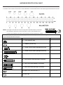
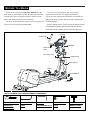
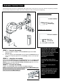
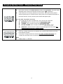
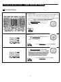
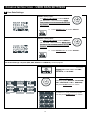
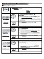
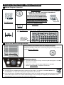
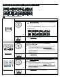
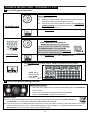
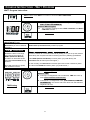
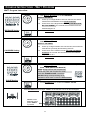
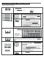
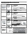
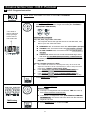
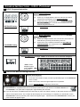
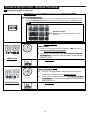
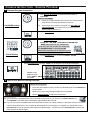
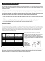
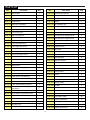
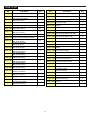
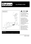
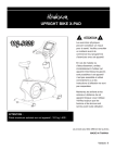
OWNER’S MANUAL CE-8.0LC Product May Vary Slightly From Pictures MADE IN TAIWAN Exercise can present a health risk. Consult a physician before beginning any exercise program with this equipment. If you feel faint or dizzy, immediately discontinue use of this equipment. Serious bodily injury can occur if this equipment is not assembled and used correctly. Serious bodily injury can also occur if all instructions are not followed. Keep children and pets away from equipment when in use. Always make sure all bolts and nuts are tightened prior to each use. Follow all safety instructions in this manual. CAUTION: WEIGHT ON THIS PRODUCT SHOULD NOT EXCEED 180KG / 400LBS. VERSION: II SAFETY INSTRUCTIONS WARNING: To reduce the risk of serious injury, read the following Safety Instructions before using the Elliptical Trainer. 1. Read all warnings posted on the Elliptical Trainer. 2. Read this Owner's Manual and follow it carefully before using the Elliptical Trainer. Make sure that it is properly assembled and tightened before use. 3. We recommend that two people be available for assembly of this product. 4. Keep children away from the Elliptical Trainer. Do not allow children to use or play on the Elliptical Trainer. Keep children and pets away from the Elliptical Trainer when it is in use. 5. It is recommended that you place this exercise equipment on an equipment mat. 6. Set up and operate the Elliptical Trainer on a solid level surface. Do not position the Elliptical Trainer on loose rugs or uneven surfaces. 7. Inspect the Elliptical Trainer for worn or loose components prior to use. 8. Tighten/replace any loose or worn components prior to using the Elliptical Trainer. 9. Consult a physician prior to commencing an exercise program. If, at any time during exercise, you feel faint, dizzy, or experience pain, stop and consult your physician. 10. Follow your physician's recommendations in developing your own personal fitness program. 11. Always choose the workout which best fits your physical strength and flexibility level. Know your limits and train within them. Always use common sense when exercising. 12. Before using this product, please consult your personal physician for a complete physical examination. 13. Do not wear loose or dangling clothing while using the Elliptical Trainer. 14. Never exercise in bare feet or socks; always wear correct footwear, such as running, walking, or cross-training shoes. 15. Be careful to maintain your balance while using, mounting, dismounting, or assembling the Elliptical Trainer, loss of balance may result in a fall and serious bodily injury. 16. Keep both feet firmly and securely on the Foot Pedals while exercising. 17. The Elliptical Trainer should not be used by persons weighing over 400 pounds /181 kgs. 18. The Elliptical Trainer should be used by only one person at a time. 19. Use two people to assemble and move the Elliptical Trainer. 20. Maintenance: Replace the defective components immediately and/or keep the equipment out of use until repair the equipment completely. 21. Make sure that adequate space is available for access to and passage around the Elliptical Trainer; keep at least a distance of 1 meter from any obstruction object while using the machine. WARNING: Before starting any exercise or conditioning program you should consult with your personal physician to see if you require a complete physical exam. This is especially important if you are over the age of 35, have never exercised before, are pregnant, or suffer from any illness. READ AND FOLLOW THE SAFETY PRECAUTIONS. FAILURE TO FOLLOW THESE INSTRUCTIONS CAN RESULT IN SERIOUS BODILY INJURY 2 HARDWEAR IDENTIFICATION CHART This chart is provided to help identify the hardware used in the assembly process. Place the washers, the end of the bolts, or screws on the circles to check for the correct diameter. Use the small scale to check the length of the bolts and screws. NOTE: The length of all bolts and screws except those with flat heads is measured from below the head to the end of the bolt or screw. Flat head bolts and screws are measured from the top of the head to the end of the bolt or screw. After unpacking the unit, open the hardware bag and make sure that you have all the following items. Some hardware may be already attached to the part. Part No. and Description Q’TY 66 4 Lock Washer (M8) 70 Washer (8x38x2.0t) 4 80 Screw, Round Head (M5xp0.8x15mm) 18 81 Screw, Round Head (M5xp0.8x50mm) 2 83 Bolt, Socket Head (M8xp1.25x10mm) 8 90 Bolt, Button Head (M10xp1.5x85mm) 2 94 Bolt, Hex Head (M8xp1.25x65mm) 4 95 Bolt, Hex Head (M10xp1.5x50mm) 2 104 Nylon lock Nut (M10xp1.5) 2 105 Nut Cap 2 3 “BEFORE YOU BEGIN” Too often, our busy lifestyles limit our time and Thank you for choosing the CE-8.0LC Elliptical. We take great pride in producing this quality product and hope it will opportunity to exercise. The equipment provides a provide many hours of quality exercise to make you feel convenient and simple method to begin your assault on better, look better and enjoy life to its fullest. getting your body in shape and achieving a happier and Yes, it's a proven fact that a regular exercise program can healthier lifestyle. improve your physical and mental health. Before reading further, please review the drawing below and familiarize yourself with the parts that are labeled. Read this manual carefully before using the equipment. Console Foam Grip Handlebar Pulse Sensor Plate Accessory Tray Upright Post Main Frame Pedal Front Stabilizer Leveler Rear Stabilizer THE FOLLOWING TOOLS ARE INCLUDED FOR ASSEMBLY: MULTI WRENCH TOOL ALLEN WRENCH PHILLIPS SOCKET WRENCH T-HANDLE SOCKET W/ PHILLIPS (6 mm) SCREWDRIVER (6mm) (13mm) WRENCH (17MM) SCREWDRIVER 4 “ASSEMBLY INSTRUCTIONS” Place all parts from the box in a cleared area and position them on the floor in front of you. Remove all packing materials from your area and place them back into the box. Read each step carefully before beginning. Detailed Lever- drawing 1 Stabilizer Nut (118) Leveler (58) Detailed Lever- drawing 2 Stabilizer Nut (118) Screw line Leveler (58) LEVELING: After placing the STEP 1 – Leveler Assembly a. b. Attach the Leveler x 4 (58) to the Front Stabilizer (2) and the Rear Stabilizer (3). Be sure to tighten the Leveler (58) securely against the Stabilizers (2, 3) until screw completely tightened as the drawing 1 shown on the top right corner. STEP 2 – Stabilizer Assembly Attach the Front Stabilizer (2) and the Rear Stabilizer (3) onto the Main Frame (1) and secure with the 4 x Washers (8x38x2.0t) (70), the 4 x Lock Washers (M8)(66) and the 4 x Hex Head Bolts (M8xp1.25x65mm) (94) with the socket wrench(13mm) (See picture above) STEP 3 – Leveler Assembly Tighten one Leveler (58) under the middle of the Main Frame (1). NOTE: It will be easier to attach the Leveler (58) under the Main Frame (1) by placing one Styrofoam (or any stationary object) under one side of the Main Frame (1). 5 equipment in the intended location for use, Check the stability of the equipment. If the equipment is not level, reviewing the following direction: Loosen the Leveler (58) to make the Nut (118) become less tight. Adjust the Leveler (58) for leveling. Tighten the Nut (118) securely against the Stabilizer to lock the Leveler (58) in the stable position as the drawing 2 shown. “ASSEMBLY INSTRUCTIONS” NOTE: Please do not fully tighten Bolts (95) until Step. 8 for the easy assembly NOTE: Do not remove the lock nuts during assembly (103) STEP 4 – Upright Sleeve Assembly CAUTION: Be careful not to damage the Middle Connection Wire (109) while assembling Step 4 to 6. Slide the Upright Sleeve (22) onto the Upright Post (4). Refer to the drawing above. Make sure the direction of the Upright Sleeve (22) is in the correct position. STEP 5 – Upright Post Assembly a. Check that 2 x Nylon lock Nuts (M10x8t) (103) have preassembled into the front of the Main Frame (1) as FIG1 illustration shows on the top right corner, making sure that the slotted bracket of the upright post slides between the nuts and the frame. b. Insert the Upright Post (4) onto the Main Frame (1) and slightly secure with the 2 x Hex Head Bolts (M10xp1.5x50mm) (95) by using the T-Handle SOCKET WRENCH(17mm) as shown. NOTE: Please do not fully tighten Bolts (95) or lock nuts (103) until Step. 7 Has been COMPLETED STEP 6 – Wire Assembly Plug the Middle Connection Wire (109) into the Lower Connection Wire (110). 6 “ASSEMBLY INSTRUCTIONS” STEP 7 – Pedal Support Arm & Pivoting Arm Assembly a. Attach the Left Pedal Support Arm (10) onto the Left Pivoting Arm (8) and secure with the 1x Button Head Bolt (M10xp1.5x85mm) (90) and 1 x Nylon lock Nut (M10xp1.5) (104). b. Press the Nut Cap (105) onto the Nylon lock Nut (M10xp1.5) (104). c. Repeat the above procedure to attach the Right Pedal Support Arm (11) onto the Right Pivoting Arm (9). NOTE: Please make sure Bolts (90) are inserted from the inside of the Pivoting Arm Note: make sure the bolts are fully tightened to avoid noise and the Nuts (104) and Nut Caps (105) are installed from the outside STEP 8 – Front Decoration Cover Assembly a. Please go back to fully tighten with the 2 x Hex Head Bolts (M10xp1.5x50mm) (95) and the 2 x Lock nuts (103) with the T-Handle SOCKET WRENCH (17mm) as shown. b. Attach the Front Decorative Upright Cover (21) onto the front of the Main Frame (1) with the 2 x Round Head Screws (M5xp0.8x50mm) (81). c. Place the Logo Sticker on the surface of the Front Decorative Upright Cover (21). A logo sticker is located in one of the hardware boxes. d. Slide the Upright Sleeve (22) down to cover the open area of the Main Frame (1). 7 “ASSEMBLY INSTRUCTIONS” STEP 9 – Pedal Assembly a. Attach the Left Pedal Assembly (33L) onto the pedal arm plate that is located in the middle of the Left Pedal Support Arm (10) and secure with the 4x Socket Head Bolt (M8xp1.25x10mm) (83). b. Repeat the above procedure to attach the Right Pedal Assembly (33R) onto the Right Pedal Support Arm (11). 8 “ASSEMBLY INSTRUCTIONS” STEP 10 – Console Bracket Assembly CAUTION: Be careful not to damage the Middle Pulse Sensor Wire (112) while assembling STEP 9. Slide the Console Bracket (18) onto the Upright Post (4) as the FIG1 illustration shows on the top right corner. STEP 11– Console Fixed Bracket Assembly NOTE: For shipping purpose, the 4 x Button Head Bolts (M8xp1.25x12mm) (87) and 4 x Lock Washers (M8)(66) are attached on the Upright Post (4). a. Remove the 4 x Button Head Bolts (M8xp1.25x12mm)(87) and 4 x Lock Washers (M8)(66) from the Upright Post (4). b. Attach the Console Fixed Bracket (43) onto the Upright Post (4) and secure with the 4 x Button Head Bolts (M8xp1.25x12mm)(87) and 4 x Lock Washers (M8)(66) STEP 12 – Stationary Handlebar & Wire Assembly NOTE: For shipping purpose, the Button Head Bolts (M8xp1.25x16mm)(88) and Lock Washers (M8)(66) are attached on the Stationary Handlebar (5). a. Remove the 4 x Button Head Bolts (M8xp1.25x16mm)(88) and 4 x Lock Washers (M8)(66) from the Stationary Handlebar (5). b. Connect the Middle Pulse Sensor Wire (112) and the Lower Pulse Sensor Wire (113) to the Stationary Handlebar (5). NOTE: After connecting the wires’ pins, slightly and gently pull two sides of wires to test and make sure whether the wires are fully connected. c. Insert the Stationary Handlebar (5) into the Upright Post (4) and secure with the 4 x Button Head Bolts (M8xp1.25x16mm)(88) and 4 x Lock Washers (M8)(66). 9 “ASSEMBLY INSTRUCTIONS” STEP 13 – Wire Assembly a. Connect the Upper Pulse Sensor Wire (111) to the Middle Pulse Sensor Wire (112). b. Connect the Upper Connection Wire (108) to the Middle Connection Wire (109). NOTE: The number of wire pin should be the same for both wires to connect with as the drawing shown on the right. STEP 14 – Console & Console Bracket Assembly a. Place the Console (17) onto the Upright Post (4) and secure with the Round Head Screws (M5xp0.8x15mm) (80). b. Attach the Console Back Cover (19) to the Console (17) under the Stationary Handlebar (5) and secure with the Round Head Screws (M5xp0.8x15mm) (80). c. Slide the Console Bracket (18) onto the Console (17) and secure with the Round Head Screws (M5xp0.8x15mm) (80). STEP 15 – Accessory Tray Assembly NOTE: For shipping purpose, the Round Head Screws (M5xp0.8x15mm) (80) are attached on the Upright Post (4). a. Remove the Round Head Screw (M8xp1.25x15mm) (80) from the Upright Post (4). b. Attach the Accessory Tray (23) onto the Upright Post (4) and secure with the Round Head Screw (M5xp0.8x15mm) (80). 10 “ASSEMBLY INSTRUCTIONS” STEP 16 – Upper Handlebar Assembly NOTE: For shipping purpose, the Button Head Bolts (M8xp1.25x16mm)(88) and Lock Washers (M8)(66) are attached on the Left and Right Action Handlebar (6, 7). a. Remove the 8x Button Head Bolts (M8xp1.25x16mm) (88) and 8 x Lock Washers (M8) (66) from the Left and Right Action Handlebar (6, 7). b. Following the assembly drawing, insert the Right Action Handlebar (7) onto the Right Pivoting Arm (9) and secure with the 4x Button Head Bolts (M8xp1.25x16mm)(88) and 4 x Lock Washers (M8)(66). c. Repeat the above procedure to insert and secure the Left Action Handlebar (6) onto the Left Pivoting Arm (8). STEP 17 – Action Arm Cover Assembly a. Place the Front Action Arm Cover (31) and the Back Action Arm Cover (32) over the Right Pivoting Arm (9). b. Fasten the Covers together with the 4 x Round Head Screws (M5xp0.8x15mm) (80). c. Repeat the above procedure to place the Front Action Arm Cover (31) and the Back Action Arm Cover (32) at both sides of the Left Pivoting Arm (8). For the final step, make sure all the bolts and nuts are tighten securely before using. 11 “OPERATION INSTRUCTIONS” A. POWER SUPPLY The power connects to the front of the Main Frame (1.) Plug the adaptor’s Power Cord (106B) into an 110v electrical outlet. B. CONSOLE ANGLE ADJUSTMENT A To get the best viewable angle, press the area A or B to adjust the display up or down. B C. HOW TO MOVE THE ELLIPTICAL Move this elliptical by lifting from the front stabilizer and roll the elliptical on the wheels located on the rear stabilizer. This elliptical may reqire two people to move. Make sure the floor is level while moving the elliptical. 12 “CONSOLE INSTRUCTIONS” Take a few minutes to review the console layout. Below is an overview of the console’s features and functions We recommend that you use the console to help vary your workout routine and keep you focused on your progress toward your fitness goals. The computer programs and user feedback is a great source of motivation, often assisting you to take your workout to the next level Speaker Reading Rack Power ON a. Make sure to plug the adapter into an electrical outlet. b. Pedaling or pressing any keys to active the console. The console display will then light up with a short beep sound, indicating the console is ready for use Power Off The console will automatically go to SLEEP mode after 4 minutes of inactivity Console Program List 13 “CONSOLE INSTRUCTIONS – CONSOLE BUTTONS ” Console Buttons a. Press ST/STOP to begin your exercise. b. Press ST/STOP to stop and pause all functions during your exercise program. All the data on the display will pause. c. To resume the program, press ST/STOP again to continue until the program has finished. d. Quick start Manual: press ST/STOP, without selecting any programs. Press ENTER to confirm the selected values of TIME, DISTANCE, CALORIES, PULSE, GENDER, AGE, HEIGHT, WIGHT and RESISTANCELEVEL FOR each interval. RESET function: Hold the RESET button, all the data will reset to 0 and the console will return to POWER ON status a. Press + to increase the values of TIME, DISTANCE, CALORIES, PULSE and RESISTANCELEVEL in each time interval. b. Press - to decrease the values of TIME, DISTANCE, CALORIES, PULSE and RESISTANCELEVEL in each time interval. c. Press + or – button to select your GENDER, AGE, HEIGHT and WEIGHT a. NOTE: A Chest Belt must be worn or properly hold the Heart Rate Sensors on the handrails with both hands before using the PULSE RECOVERY feature. PULSE RECOVERY will only function if the computer receives a heart rate signal. b. PULSE RECOVERY button measures how quickly a resting heat rate is achieved after exercising. This feature is used to measure fitness improvement c. The console will monitor your pulse for 60 seconds and calculate a HEART RATE RECOVERY value from F1.0 to F6.0. F1.0 is best; F6.0 is worst (For Reference Only) d. The readout should only be used as a comparison between workouts. It’s recommended to use right after any aerobic exercise. Stop exercising before using the feature. e. Your pulse will be displayed few seconds after the heart symbol “ f. ” is displayed If you do not place your hands correctly, and a few seconds pass without a pulse input, the console will turn off the pulse circuit. The console will then display an error message “P”. Place your hands back on the Pulse Sensors correctly, then the pulse readout will appear again. 14 “CONSOLE INSTRUCTIONS – CONSOLE BUTTONS ” Console Functions STOP: When “STOP” flashes, this indicates is paused. TIME: Count Up: If a target time is not selected, TIME will count up from 0:00 to maximum 99:59 minutes. Count Down: If a target time is set, (1:00 TO 99:00; 1 MINUTE INCREMENTS), the console will count down from that selected target time to 0:00. SPEED: Display range: 0.0~99.9 mile/h. RPM: Display range: 0~999. DISTANCE: Count Up: If a target distance is not selected, the distance will count up from 0:00 to 99.99 mile. Count Down: If a target distance is set, (0 TO 99.50; 0.50 MILE INCREMENT), the console will count down from the selected target to 0. M: “M” is indicating “Mile”. U0 ~ U4: “U” stands for “USER DATA”. U1~U4 once the user data is set it is stored in the computers memory. SEX: “Male ”, or “Female ”. AGE: Display range: 10 ~ 99 years old; 1 year-old increment NOTE: Although the console allows input for age beginning at 10 years old, the product is not recommended for use by children HEIGHT: Display range: 40 ~ 80 inches; 1 inch increment; this product is not recommended for use by children WEIGHT: Display range: 40 ~ 350 LBS; 1 LBS increment; this product is not recommended for use by children 15 “CONSOLE INSTRUCTIONS”– CONSOLE FUNCTIONS” PULSE: Place both of hands on the Pulse Sensors located on the Handlebar. The pulse will be displayed within several seconds after the heart symbol “ ” is displayed If the hands are not correctly positioned on the sensor, and a few seconds passes without a pulse input, the console will turn off the pulse circuit. Replace hands back on the Pulse Sensors correctly, and the pulse readout will appear again 55%, 75%, 90%, Tag of max. heart rate: The console will use age to calculate 55%, 75%, 90% of max. heart rate. BEGINNER: 55% of maximum heart rate; 55% of (220 – age) TRAINER: 75% of maximum heart rate; 75% of (220 – age) ACTIVE TRAINER: 90% of maximum heart rate; 90% of (220 – age) TARGE H.R.: Allows the user to select the desired target heart rate value 30 ~ 240 BPM (beats per minute) ; 1 BPM increment CALORIES: Count Up: If target calories are not selected, this measures total calories your body burned during exercise Count Down: If target calories are entered (10 ~ 990 ; 10 calorie increments, the console will count down from the selected target calories to 0 WATT: Display range: 0 ~ 999 Watt 16 “CONSOLE INSTRUCTIONS – USER DATA SETTINGS” “1” User Data Settings: U0~U4 user setup: a. After the console lights up with a short beep sound, the display will flash “U0”. “U0” is the default user setting value. Once user information has been stored. The default setting value will change to U1~ U4. NOTE: “U” stands for “USER PROFILE”. b. Use ▲(+) or ▼(-) button to select U0 ~ U4. c. Press ENTER button to confirm the user profile. GENDER setup: a. Use ▲(+) or ▼(-) button to select gender “Male ”, or “Female ”. b. Press ENTER button to confirm GENDER. AGE setup: a. Use ▲(+) or ▼(-) button to select AGE (10~99 years old; 1 year increments). NOTE: Although the console allows input for age beginning at 10 years old, the product is not recommended for use by children b. Press ENTER button to confirm AGE. 17 “CONSOLE INSTRUCTIONS – USER DATA SETTINGS” “2” User Data Settings: HEIGHT setting value: a. Use ▲(+) or ▼(-) button to select HEIGHT (40~80 inches; 1 inch increments). NOTE: This product is not recommended for use by children b. Press ENTER button to confirm HEIGHT. WEIGHT setting value: a. Use ▲(+) or ▼(-) button to select WEIGHT (40~350 LBS; 1 LB increments). NOTE: This product is not recommended for use by children b. Press ENTER button to confirm WEIGHT. User Profile Settings complete (SEX, AGE, HEIGHT and WEIGHT), Choose program Press ST/STOP to start in the MANUAL program without the need to set TIME, DISTANCE, or CALORIES. Use ▲(+) or ▼(-) buttons to select an exercise program (MANUAL, PROGRAM, WATT, PERSONAL, H.R.C., RANDOM). And press ENTER button to confirm. To choose P1 ~ P12, press the program icon and press ENTER button to confirm. 18 “CONSOLE INSTRUCTIONS – MANUAL PROGRAM” “1” Manual Program Instruction: a. MANUAL button: Press MANUAL icon button to enter MANUAL PROGRAM. b. Press ENTER button to confirm. c. Use ▲(+) or ▼(-) button to set the target TIME. NOTE for TIME: Count Up: If a target time was not selected, TIME will count up from 0:00 to maximum 99:59 minutes. Count Down: If a target time is set, (1:00 TO 99:00; 1 MINUTE INCREMENTS), the console will count down from that selected target time to 0:00. TIME Setting d. Press ENTER button to confirm the value of TIME. e. Use ▲(+) or ▼(-) button to set the target DISTANCE. NOTE for DISTANCE: Count Up: If a target distance was not selected, this would measure the total distance from 0:00 to 99.99 mile. Count Down: If a target distance is set, (0 TO 99.50; 0.50 MILE INCREMENT), the console will count down from the selected target to 0. DISTANCE Setting f. Press ENTER button to confirm the value of DISTANCE. g. Use ▲(+) or ▼(-) button to set the target CALORIES. NOTE for CALORIES: Count Up: If target calories were not selected, this measures total calories your body burned during exercise Count Down: If target calories are entered (10 ~ 990 ; 10 calorie increments, the console will count down from the selected target calories to 0 CALORIES Setting h. Press ENTER button to confirm the value of CALORIES. 19 “CONSOLE INSTRUCTIONS – MANUAL PROGRAM” “1” Manual Program Instruction: i. Use ▲(+) or ▼(-) button to select the desired value of TARGET PULSE (30 ~ 240 BPM; 1 BPM (BEATS PER MINUTE) . NOTE: During exercise, the console will monitor your pulse and compare the value of your pulse with TARGET PULSE. The value of your actual PULSE will keep flashing to warn you to slow down or lower the RESISTANCE level if your pulse value PULSE Setting Target Pulse is greater than TARGET PULSE. j. Press ENTER button to confirm the value of TARGET PULSE. k. Press ST/STOP button to begin exercise. “STOP” on the left side corner would then disappear. “STOP” would disappear when press “START” to exercise “2” Instruction Note for During Exercise: During workout, the resistance level can changed at any time: Change the resistance level (from 1 to 24 levels) at any time during workout by pressing ▲(+) or ▼(-) button. Torque/Tension Level Speaker Sound System: a. To use the music feature, simply connect any MP3/CD player to the LINE IN jack on the console. b. Listen to the music, either through headphones or speakers. c. Use the “Volume Knob” to adjust the sound level. No Pulse signal: You must wear a compatible heart rate chest strap or place both of your hands on the Pulse Sensors on the Handlebar. Your pulse will be displayed in approximately few seconds. If you do not wear a compatible heart rate chest strap or place your hands correctly on the pulse sensors, the console will turn off the pulse circuit. The console will then display an error message “P”. Replace your hands back on the Pulse Sensors correctly, and the pulse readout will appear again 20 “CONSOLE INSTRUCTIONS – PROGRAM (P1~P12)” “1” P1~P12 Program Instruction: a. PROGRAM button: Press PROGRAM icon button to enter PROGRAM (P1 ~ P12). b. Use ▲(+) or ▼(-) button to select the desired PROGRAM (P1 ~ P12). or c. Directly press PROGRAM (P1 ~ P12) icon to enter the desired workout program. d. Press ENTER button to confirm. Use ▲(+) or ▼(-) button to set the target DISTANCE. NOTE for DISTANCE: Count Up: If a target distance was not selected, this would measure the total distance from 0:00 to 99.99 mile. Count Down: If a target distance is set, (0 TO 99.50; 0.50 MILE INCREMENT), the console will count down from the selected target to 0. TIME Setting e. Press ENTER button to confirm TIME. f. Use ▲(+) or ▼(-) button to set the target DISTANCE. NOTE for DISTANCE: Count Up: If a target distance was not selected, this would measure the total distance from 0:00 to 99.99 mile. Count Down: If the target distance is set (0 TO 99.50; 0.50 MILE INCREMENT), the console will count down from the selected target distance to 0. DISTANCE Setting g. Press ENTER button to confirm DISTANCE. 21 “CONSOLE INSTRUCTIONS – PROGRAM (P1~P12)” “1” P1~P12 Program Instruction: h. Use ▲(+) or ▼(-) button to set CALORIES. NOTE for CALORIES: Count Up: If target calories were not selected, this measures total calories your body burned during exercise Count Down: If the target calories have been set (10 ~ 990 ; 10 calories increment, the console will count down from the CALORIES Setting selected target calories to 0 i. Press ENTER button to confirm CALORIES. j. Use ▲(+) or ▼(-) button to set the TARGET PULSE (30 ~ 240 BPM; 1 BPM (BEATS PER MINUTE) . NOTE: During exercise, the computer will monitor the pulse and compare the actual pulse with TARGET PULSE. The actual PULSE reading will keep flashing as an indication to slow down or lower the RESISTANCE level PULSE Setting Target Pulse k. Press ENTER button to confirm TARGET PULSE. l. Press ST/STOP button to begin exercise. “STOP” on the left side corner will then disappear. “STOP” would disappear when press “START” is pressed “2” Instruction Note for During Exercise: Speaker Sound System: a. To use the music feature, simply connect any MP3/CD player to the LINE IN jack on the console. b. Listen to the music, either through headphones or speakers. c. Use the “Volume Knob” to adjust the sound level. No Pulse signal: You must wear a compatible heart rate chest strap or place both of your hands on the Pulse Sensors on the Handlebar. Your pulse will be displayed in approximately few seconds. If you do not wear a compatible heart rate chest strap or place your hands correctly on the pulse sensors, the console will turn off the pulse circuit. The console will then display an error message “P”. Replace your hands back on the Pulse Sensors correctly, and the pulse readout will appear again 22 “CONSOLE INSTRUCTIONS – WATT PROGRAM” WATT Program Instruction: a. WATT button: Press WATT icon button to enter the WATT PROGRAM. b. Use ▲(+) or ▼(-) button to select the target WATTs (10~350 WATT; 5 WATT INCREMENTS). NOTE for WATT Program: The computer is equipped with LEVEL CONTROL and WATT CONTROL function. c. Press ENTER button to confirm the value of WATT. Before operating WATT PROGRAM, review the difference between the CONSTANT POWER and the CONSTANT RESISTANCE function: Level Control (Constant Resistance) in most of workout Watt Control (Constant Power) in WATT program programs The resistance depends on the value of RPM (Rotate Per Minute.) “RPM RESISTANCE -“RPM RESISTANCE ; RPM RESISTANCE ” Resistance does not change In order to remain at a consistent effort level (watts) (once you set up the desired even though the quantity of Watt value), the computer will start monitoring the user’s pedaling speed/RPM. RPMs (Rotate Per Minute) If the RPMs (Rotate Per Minute) increase (when you pedal faster), the increases or decreases under the Level Control Mode during Resistance will decrease (becomes lighter.) workout. On the contrary, the Resistance increases (becomes heavier resistance) when the value of the RPMs decreases (when you pedal slower.) No matter how fast you pedal, the resistance is fixed. d. Use ▲(+) or ▼(-) button to set the TIME. NOTE for TIME: Count Up: If a target time was not selected, TIME will count up from 0:00 to maximum 99:59 minutes. Count Down: If a target time is set, (1:00 TO 99:00; 1 MINUTE INCREMENTS), the console will count down from that selected TIME Setting target time to 0:00. e. Press ENTER button to confirm TIME. 23 “CONSOLE INSTRUCTIONS – WATT PROGRAM” WATT Program Instruction: f. Use ▲(+) or ▼(-) button to set the DISTANCE. NOTE for DISTANCE: Count Up: If a target distance was not selected, this would measure the total distance from 0:00 to 99.99 mile. Count Down: If the target distance is set (0 TO 99.50; 0.50 MILE INCREMENT), the console will count down from the selected target to 0. DISTANCE Setting g. Press ENTER button to confirm DISTANCE. h. Use ▲(+) or ▼(-) button to select the desired value of CALORIES. NOTE for CALORIES: Count Up: If target calories were not selected, this measures total calories your body burned during exercise CALORIES Setting Count Down: If the calories are set (10 ~ 990 ; 10 calories increment, the console will count down from the selected target calories to 0 i. Press ENTER button to confirm CALORIES. j. Use ▲(+) or ▼(-) button to set the TARGET PULSE (30 ~ 240 BPM; 1 BPM (BEATS PER MINUTE) . NOTE: During exercise, the computer will monitor the pulse and compare the actual pulse with TARGET PULSE. The actual PULSE reading will keep flashing as an indication to slow down or lower the RESISTANCE level. PULSE Setting k. Press ENTER button to confirm the TARGET PULSE. l. Press ST/STOP button to begin. “STOP” on the left side corner will then disappear. “STOP” would disappear when press “START” is pressed 24 “CONSOLE INSTRUCTIONS – PERSONAL PROGRAM” Personal Program Instruction: a. PERSONAL button: Press the PERSONAL icon button to enter PERSONAL PROGRAM. b. Press ENTER button to confirm. c. The PERSONAL PROGRAM allows the user to manually set the RESISTANCE level (from 1 to 24 levels), the console will divide the time into 16 time intervals. d. The resistance can be adjusted in each interval by using ▲(+) or ▼(-) button to adjust. e. Press ENTER button to confirm the intensity setting in interval 1. Continue following the above process 16 time intervals (step d. and e.) to complete creating the personal program. NOTE: Under the U1~U4 profiles, the program profile will be stored in the memory after setup. However, you can modify the profile anytime under the STOP mode. f. Press ST/STOP button to begin. “STOP” on the left side corner will then disappear. “STOP” would disappear when press “START” is pressed To select quantity of TIME, DISTANCE, CALORIES and PULSE, press ST/STOP button again to stop and pause all console functions. All the data on the display will then pause. g. TIME value will start flashing, use ▲(+) or ▼(-) button to select the amount of TIME. NOTE for TIME: Count Up: If a target time was not selected, TIME will count up from 0:00 to maximum 99:59 minutes. Count Down: If a target time is set, (1:00 TO 99:00; 1 MINUTE INCREMENTS), the console will count down from TIME Setting that selected target time to 0:00. h. Press ENTER button to confirm the value of TIME. 25 “CONSOLE INSTRUCTIONS – PERSONAL PROGRAM” Personal Program Instruction: Use ▲(+) or ▼(-) button to select the desired value of i. DISTANCE. NOTE for DISTANCE: Count Up: If a target distance was not selected, this would measure the total distance from 0:00 to 99.99 mile.