1
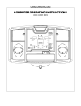
OWNER’S
MANUAL
CE-8.0LC
USER WEIGHT LIMITATION:
400lbs(181kgs)
SERIAL NUMBER (found on frame):_____________________
VERSION: IHP- I
SAFETY INSTRUCTIONS
WARNING: To reduce the risk of serious injury, read the following Safety Instructions before using the
Elliptical Trainer.
1. Read all warnings posted on the Elliptical Trainer.
2. Read this Owner's Manual and follow it carefully before using the Elliptical Trainer. Make sure that it is properly
assembled and tightened before use.
3. We recommend that two people be available for assembly of this product.
4. Keep children away from the Elliptical Trainer. Do not allow children to use or play on the Elliptical Trainer. Keep
children and pets away from the Elliptical Trainer when it is in use.
5. It is recommended that you place this exercise equipment on an equipment mat.
6. Set up and operate the Elliptical Trainer on a solid level surface. Do not position the Elliptical Trainer on loose rugs or
uneven surfaces.
7. Inspect the Elliptical Trainer for worn or loose components prior to use.
8. Tighten/replace any loose or worn components prior to using the Elliptical Trainer.
9. Consult a physician prior to commencing an exercise program. If, at any time during exercise, you feel faint, dizzy, or
experience pain, stop and consult your physician.
10. Follow your physician's recommendations in developing your own personal fitness program.
11. Always choose the workout which best fits your physical strength and flexibility level. Know your limits and train within
them. Always use common sense when exercising.
12. Before using this product, please consult your personal physician for a complete physical examination.
13. Do not wear loose or dangling clothing while using the Elliptical Trainer.
14. Never exercise in bare feet or socks; always wear correct footwear, such as running, walking, or cross-training shoes.
15. Be careful to maintain your balance while using, mounting, dismounting, or assembling the Elliptical Trainer, loss of
balance may result in a fall and serious bodily injury.
16. Keep both feet firmly and securely on the Foot Pedals while exercising.
17. The Elliptical Trainer should not be used by persons weighing over 400 pounds /181 kgs.
18. The Elliptical Trainer should be used by only one person at a time.
19. Use two people to assemble and move the Elliptical Trainer.
20. Maintenance: Replace the defective components immediately and/or keep the equipment out of use until repair the
equipment completely.
21. Make sure that adequate space is available for access to and passage around the Elliptical Trainer; keep at least a
distance of 1 meter from any obstruction object while using the machine.
WARNING: Before starting any exercise or conditioning program you should consult with your personal physician to see if
you require a complete physical exam. This is especially important if you are over the age of 35, have never exercised before,
are pregnant, or suffer from any illness.
READ AND FOLLOW THE SAFETY PRECAUTIONS. FAILURE TO FOLLOW THESE
INSTRUCTIONS CAN RESULT IN SERIOUS BODILY INJURY
2
HARDWEAR IDENTIFICATION CHART
This chart is provided to help identify the hardware used in the assembly process. Place the washers, the end of the bolts,
or screws on the circles to check for the correct diameter. Use the small scale to check the length of the bolts and screws.
NOTE: The length of all bolts and screws except those with flat heads is measured
from below the head to the end of the bolt or screw. Flat head bolts and
screws are measured from the top of the head to the end of the bolt or screw.
After unpacking the unit, open the hardware bag and make sure that you have all the following items. Some hardware
may be already attached to the part.
Part No. and Description
Q’TY
66
Lock Washer (M8)
4
70
Washer (8x38x2.0t)
4
80
Screw, Round Head (M5xp0.8x15mm)
18
81
Screw, Round Head (M5xp0.8x50mm)
2
83
Bolt, Socket Head (M8xp1.25x10mm)
8
90
Bolt, Button Head (M10xp1.5x85mm)
2
94
Bolt, Hex Head (M8xp1.25x65mm)
4
95
Bolt, Hex Head (M10xp1.5x50mm)
2
104 Nylon lock Nut (M10xp1.5)
2
105 Nut Cap
2
3
“BEFORE YOU BEGIN”
Too often, our busy lifestyles limit our time and
Thank you for choosing the CE-8.0LC Elliptical. We take
great pride in producing this quality product and hope it will
opportunity to exercise. The equipment provides a
provide many hours of quality exercise to make you feel
convenient and simple method to begin your assault on
better, look better and enjoy life to its fullest.
getting your body in shape and achieving a happier and
healthier lifestyle.
Yes, it's a proven fact that a regular exercise program can
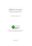
Before reading further, please review the drawing below
improve your physical and mental health.
and familiarize yourself with the parts that are labeled.
Read this manual carefully before using the equipment.
Console
Foam Grip
Handlebar
Pulse Sensor
Plate
Accessory Tray
Upright Post
Main Frame
Pedal
Front Stabilizer
Leveler
Rear Stabilizer
THE FOLLOWING TOOLS ARE INCLUDED FOR ASSEMBLY:
MULTI WRENCH TOOL
ALLEN WRENCH
PHILLIPS
SOCKET WRENCH
T-HANDLE SOCKET
W/ PHILLIPS
(6 mm)
SCREWDRIVER (6mm)
(13mm)
WRENCH (17MM)
SCREWDRIVER
4
“ASSEMBLY INSTRUCTIONS”
Place all parts from the box in a cleared area and position them on the floor in front of you. Remove all packing mat erials
from your area and place them back into the box. Read each step carefully before beginning.
Detailed Lever- drawing 1
Stabilizer
Adjustment Plate
Leveler (58)
Detailed Lever- drawing 2
Stabilizer
Adjustment Plate
Screw line
Leveler (58)
LEVELING: After placing the
STEP 1 – Leveler Assembly
a.
b.
Attach the Leveler x 4 (58) to the Front Stabilizer (2) and the Rear
Stabilizer (3).
Be sure to tighten the Leveler (58) securely against the Stabilizers (2, 3)
until screw completely tightened as the drawing 1 shown on the top right
corner.
STEP 2 – Stabilizer Assembly
Attach the Front Stabilizer (2) and the Rear Stabilizer (3) onto the Main
Frame (1) and secure with the 4 x Washers (8x38x2.0t) (70), the 4 x Lock
Washers (M8)(66) and the 4 x Hex Head Bolts (M8xp1.25x65mm) (94) with
the socket wrench(13mm) (See picture above)
STEP 3 – Leveler Assembly
Tighten one Leveler (58) under the middle of the Main Frame (1).
NOTE: It will be easier to attach the Leveler (58) under the Main Frame (1) by
placing one Styrofoam (or any stationary object) under one side of the Main
Frame (1).
5
equipment in the intended
location for use, Check the
stability of the equipment. If the
equipment is not level,
reviewing the following
direction:
Loosen the Leveler (58) to
make the Adjustment Plate
become less tight.
Adjust the Leveler (58) for
leveling.
Tighten the Adjustment Plate
securely against the Stabilizer
to lock the Leveler (58) in the
stable position as the drawing
2 shown.
“ASSEMBLY INSTRUCTIONS”
NOTE: Please do not fully
tighten Bolts (95) until Step. 8
for the easy assembly
NOTE: Do not remove the lock
nuts (103) during assembly
STEP 4 – Upright Sleeve Assembly
CAUTION: Be careful not to damage the Middle Connection Wire (109) while assembling Step 4 to 6.
Slide the Upright Sleeve (22) onto the Upright Post (4).
Refer to the drawing above. Make sure the direction of the Upright Sleeve (22) is in the correct position.
STEP 5 – Upright Post Assembly
a.
Check that 2 x Nylon lock Nuts (M10x8t) (103) have preassembled into the front of the Main Frame (1) as FIG1
illustration shows on the top right corner, making sure that the slotted bracket of the upright post slides between the
nuts and the frame.
b.
Insert the Upright Post (4) onto the Main Frame (1) and slightly secure with the 2 x Hex Head
Bolts (M10xp1.5x50mm) (95) by using the T-Handle SOCKET WRENCH(17mm) as shown.
NOTE: Please do not fully tighten Bolts (95) or lock nuts (103) until Step. 7 has
been COMPLETED
STEP 6 – Wire Assembly
Plug the Middle Connection Wire (109) into the Lower Connection Wire (110).
6
“ASSEMBLY INSTRUCTIONS”
STEP 7 – Pedal Support Arm
& Pivoting Arm Assembly
a.
Attach the Left Pedal Support Arm
(10) onto the Left Pivoting Arm (8)
and secure with the 1x Button Head
Bolt (M10xp1.5x85mm) (90) and 1 x
Nylon lock Nut (M10xp1.5) (104).
b.
Press the Nut Cap (105) onto the
Nylon lock Nut (M10xp1.5) (104).
c.
Repeat the above procedure to attach
the Right Pedal Support Arm (11)
onto the Right Pivoting Arm (9).
NOTE: Please make sure Bolts (90) are
inserted from the inside of the Pivoting Arm
Note: make sure the bolts are fully tightened to avoid noise
and the Nuts (104) and Nut Caps (105) are
installed from the outside
STEP 8 – Front Decoration Cover Assembly
a.
Please go back to fully tighten with the 2 x
Hex Head Bolts
(M10xp1.5x50mm)
(95) and the 2 x
Lock nuts (103)
with the T-Handle
SOCKET WRENCH
(17mm) as shown.
b.
Attach the Front Decorative Upright
Cover (21) onto the front of the Main
Frame (1) with the 2 x Round Head
Screws (M5xp0.8x50mm) (81).
c.
Place the Logo Sticker on the surface of the
Front Decorative Upright Cover (21).
A logo sticker is located in one of the
hardware boxes.
d.
Slide the Upright Sleeve (22) down to cover the open area of the Main Frame (1).
7
“ASSEMBLY INSTRUCTIONS”
STEP 9 – Pedal Assembly
a.
Attach the Left Pedal Assembly (33L)
onto the pedal arm plate that is
located in the middle of the Left Pedal
Support Arm (10) and secure with the
4x Socket Head Bolt
(M8xp1.25x10mm) (83).
b.
Repeat the above procedure to attach
the Right Pedal Assembly (33R) onto
the Right Pedal Support Arm (11).
8
“ASSEMBLY INSTRUCTIONS”
STEP 10 – Console Bracket
Assembly
CAUTION: Be careful not to
damage the Middle Pulse Sensor Wire
(112) while assembling STEP 9.
Slide the Console Bracket (18) onto the
Upright Post (4) as the FIG1 illustration
shows on the top right corner.
STEP 11– Console Fixed Bracket Assembly
NOTE: For shipping purpose, the 4 x Button Head Bolts (M8xp1.25x12mm) (87) and 4 x Lock Washers (M8)(66) are
attached on the Upright Post (4).
a.
Remove the 4 x Button Head Bolts (M8xp1.25x12mm)(87) and 4 x Lock Washers (M8)(66) from the Upright Post
(4).
b.
Attach the Console Fixed Bracket (43) onto the Upright Post (4) and secure with the 4 x Button Head Bolts
(M8xp1.25x12mm)(87) and 4 x Lock Washers (M8)(66)
STEP 12 – Stationary Handlebar & Wire Assembly
NOTE: For shipping purpose, the Button Head Bolts (M8xp1.25x16mm)(88) and Lock Washers (M8)(66) are attached
on the Stationary Handlebar (5).
a.
Remove the 4 x Button Head Bolts (M8xp1.25x16mm)(88) and 4 x Lock Washers (M8)(66) from the Stationary
Handlebar (5).
b.
Connect the Middle Pulse Sensor Wire (112) and the Lower Pulse Sensor Wire (113) to the Stationary
Handlebar (5).
NOTE: After connecting the wires’ pins, slightly and gently pull two sides of wires to test and
make sure whether the wires are fully connected.
c.
Insert the Stationary Handlebar (5) into the Upright Post (4) and secure with the 4 x Button
Head Bolts (M8xp1.25x16mm)(88) and 4 x Lock Washers (M8)(66).
9
“ASSEMBLY INSTRUCTIONS”
STEP 13 – Wire Assembly
a.
Connect the Upper Pulse Sensor Wire (111) to the Middle Pulse Sensor Wire (112).
b.
Connect the Upper Connection Wire (108) to the Middle Connection Wire (109).
NOTE: The number of wire pin should be the same for both wires to connect with as the drawing
shown on the right.
STEP 14 – Console & Console Bracket Assembly
a.
b.
c.
Place the Console (17) onto the Upright Post (4) and secure wit h the Round Head Screws (M5xp0.8x15mm) (80).
Attach the Console Back Cover (19) to the Console (17) under the Stationary Handlebar (5) and secure with the
Round Head Screws (M5xp0.8x15mm) (80).
Slide the Console Bracket (18) onto the Console (17) and secure with the Round Head Screws (M5xp0.8x15mm)
(80).
STEP 15 – Accessory Tray Assembly
NOTE: For shipping purpose, the Round Head Screws (M5xp0.8x15mm) (80) are attached on
the Upright Post (4).
a.
Remove the Round Head Screw (M8xp1.25x15mm) (80) from the Upright Post (4).
b.
Attach the Accessory Tray (23) onto the Upright Post (4) and secure with the Round
Head Screw (M5xp0.8x15mm) (80).
10
“ASSEMBLY INSTRUCTIONS”
STEP 16 – Upper Handlebar Assembly
NOTE: For shipping purpose, the Button Head Bolts (M8xp1.25x16mm)(88) and Lock Washers (M8)(66) are attached
on the Left and Right Action Handlebar (6, 7).
a.
Remove the 8x Button Head Bolts (M8xp1.25x16mm) (88) and 8 x Lock Washers (M8) (66) from the Left and
Right Action Handlebar (6, 7).
b.
Following the assembly drawing, insert the Right Action Handlebar (7) onto the Right Pivoting Arm (9) and secure
with the 4x Button Head Bolts (M8xp1.25x16mm)(88) and 4 x Lock Washers (M8)(66).
c.
Repeat the above procedure to insert and secure the Left Action Handlebar (6) onto the Left Pivoting Arm (8).
STEP 17 – Action Arm Cover Assembly
a.
Place the Front Action Arm Cover (31) and the Back Action Arm Cover (32) over the Right Pivoting Arm (9).
b.
Fasten the Covers together with the 4 x Round Head Screws (M5xp0.8x15mm) (80).
c.
Repeat the above procedure to place the Front Action Arm Cover (31) and the Back Action Arm Cover (32) at
both sides of the Left Pivoting Arm (8).
For the final step, make sure all the bolts and nuts are tighten securely before using.
11
“OPERATION INSTRUCTIONS”
A. POWER SUPPLY
The power connects to the front of
the Main Frame (1.)
Plug the adaptor’s Power Cord
(106B) into an 110v electrical
outlet.
B. CONSOLE ANGLE ADJUSTMENT
A
To get the best viewable angle, press the area A or B to adjust the display up or down.
B
C. HOW TO MOVE THE ELLIPTICAL
Move this elliptical by lifting from the front stabilizer and roll the elliptical on the wheels located on the rear stabilizer.
This elliptical may reqire two people to move.
Make sure the floor is level while moving the elliptical.
12
COMPUTER OPERATION
Congratulations this product is equipped with the MY SMOOTH Virtual Fitness Trainer. Whether you
want to lose weight, train for a sporting event, or simply maintain a healthy lifestyle, the MY SMOOTH
Virtual Fitness Trainer provides the tools, structure and support you need to be fit and live healthy. The
5 simple steps, outlined in the customer care kit* are proven to help you lose weight, improve your
health, and make positive steps to a healthier lifestyle. These five steps combined with the tools built
into your online account, will provide you with a great start toward achieving your goals.
To set up your account, refer to the instructions in the Getting Started Guide contained in your Smooth
Fitness customer care kit or visit www.my smoothtrainer.com
*Not all Smooth Fitness products include the Smooth Customer Care Kit
13
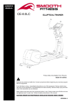
COMPUTER OPERATION
Speaker
Take a few minutes to review the console layout. Below is an overview of the console’s features and functions
We recommend that you use the cons ole to help vary your work out routine and keep you focused on your process
toward your fitness goals. The console can become an important source of motivation and interest which will help
keep you on track
Power ON
a.
b.
Make sure the item’s adaptor is correctly plugged into the socket
Pedaling or pressing any keys to active the console. The console display will then light up with a short beep sound,
indicating the console will be ready for use
Power Off
The console would automatically shut off after 5 minutes of inactivity
Program List
MANUAL
P1 WEIGHT LOSS
P2 NOV. INTERVAL
P3
INT. INTERVAL
P4
MOUNTAIN CLIMB
P5
HILL CLIMB
P6
P7
GRAD. INTERVAL
P8
PLATEAU
P9
ADV. INTERVAL
P10 LADDER
P12 USER 2
P13 H.R.C.
ROLLING HILLS
P14 H.R.C. INTERVAL
14
P11 USER 1
COMPUTER OPERATION
Console Buttons
a.
Press START/PAUSE to begin your exercise
b.
Press START/PAUSE again to stop and pause all functions during your exercise program. All the
data on the display will then pause.
c.
Press START/PAUSE again to resume the program and all the data displayed will continue until the
program has finished.
d.
HOLD TO RESET function: Press and hold START/PAUSE, all the data will return to 0 and the
console will return to POWER ON status.
Press ENTER to confirm the program function (PROGRAM, TIME, HEIGHT, WEIGHT, AGE, TARGET
H.R. and LEVEL in each time interval).
Press UP to increase the values of the program function (PROGRAM, TIME, HEIGHT, WEIGHT, AGE,
TARGET H.R. and LEVEL in each time interval).
Press DOWN to decrease the values of the program function (PROGRAM, TIME, HEIGHT, WEIGHT,
AGE, TARGET H.R. and LEVEL in each time interval).
**The button is only
suitable to use when the
USB is plugged into the
console**
Press MODE to review Calendar Mode.
Hold MODE for a few seconds, to go into Calendar
Mode to edit year/month/date/hour/minute.
Press Start/ Pause /Hold to reset to return
Calendar Mode
to POWER ON status.
a.
PULSE RECOVERY button measures how quickly you return
to a resting heart rate after exercising. You could use this
button to measure improvement as you get into shape.
b.
The console will monitor your pulse for 60 seconds and
calculate a HEART RATE RECOVERY value from F1.0 to
F6.0. F1.0 is the Highest; F6.0 is the Lowest (For Reference
Only).
c.
The readout should only be used as a comparison between
workouts. It’s recommended to use right after any aerobic
exercise. Stop exercising before starting this function.
d.
Your pulse will be displayed in approximately 5 seconds after
the heart symbol “
” is displayed.
NOTE:
If you don’t hold the HEART RATE SENSORS on the handrails with both hands properly, the console’s
HEART RATE value will show “0” and the main screen would show “F6.0” after the console counts down
to zero, If the sensor was unable to read your heart rate. Press stop then press the PULSE RECOVERY
button again. Replace your hands on the pulse sensors.
15
COMPUTER OPERATION
Console Buttons
Speaker Sound System:
a.
To use the music feature, simply connect any MP3/CD play er to the LI NE
IN jack on the console.
b.
Listen to the music, either through headphones or speakers.
c.
Use the “Volume Knob” to adjust the sound level.
To record your exercise and health metrics, you must log on
to www.mysmoothtrainer.com . Then sync your MY Smooth Virtual Fitness
Trainer USB device. Once complete simply plug in the MY Smooth Virtual
Fitness Trainer USB device to you compatible Smooth Fitness exercise
machine. Displayed on the equipment will be your name, weight height and
age. Press “S TART” button to begin your workout, the console will record your
exercise data automatically, every 20 seconds, to your MY Smooth Virtual
Fitness Trainer USB device. After your exercise session is complete, Insert
the MY Smooth device in to the USB port of your PC or MAC to upload your
data to The MY Smooth Virtual Fitness Trainer online health management
program. The detailed reports show your exercise and health results, trends
and recommendations to better achieve and maintain your fitness goals.
16
COMPUTER OPERATION
Console Functions
CALORIES:
Count Up: Measuring total calories your body burned during
exercise.
Display range: 0 ~ 9999.
SPEED:
Displays the current speed KM/MILE during exercise.
RPM (Rotation Per Minute):
Display range: 0 ~ 999.
TIME:
Count Up: If a target time was not selected, TIME will count
up from 0:00 to maximum 99:59 minutes.
Count Down: If you have set the target time (0:00 ~ 99:00),
the console will count down from that selected target time
down to 0:00.
WATTS:
Displays the current value of Watt during exercise.
Display range: 0 ~ 9999.
DISTANCE:
Count Up: If a target distance was not selected, this would
Count Down: If you have set the target distance, the
measure the total distance from 0:00 to 999.9 km/mile.
console will count down from that selected target distance
down to 0.
: Display POWER SUPPLY status.
HAND PULSE / HEART RATE:
To display your heart rate you must wear the chest belt or
place both of your hands on the Pulse Sensors located on
the Handlebars. Your pulse will be displayed approximately
5 seconds after the heart symbol “
” is displayed.
If you do not wear the chest belt or place your hands
correctly on the pulse sensors, the computer will shut off the
pulse circuit. To reactivate the pulse feature, properly place
your hands back on the Pulse Sensors and the pulse
readout will appear again.
: When the MY SMOOTH USB is plugged into the
console, the USB signal will be displayed on the
console.
17
COMPUTER OPERATION
GENDER:
Display range:
Male:
Female:
AGE:
Display range:
10 ~ 99 years old; in 1 year increments
NOTE: Although the console allows input for age
beginning at 10 years old, the product is not
recommended for use by children.
HEIGHT:
Display range:
3 FEET 4 INCHES ~ 7 FEET; 1 INCH increments / 101 ~ 214
CM; 1 CM increments; the product is not recommended for
use by children.
WEIGHT:
Display range:
45 ~ 400LBS; 1 LB increments / 20 ~ 181 KGS; 1 KG
increments; the product is not recommended for use by
children.
TARGET H.R.:
Display range:
50 ~ 180 BPM (beats per minute) ; 1 BPM increments.
18
COMPUTER OPERATION
“1” Press any button on the console to turn on the console
a.
Make sure that the power cord is properly plugged into the socket.
b.
The console would automatically shut off after 5 minutes of inactivity.
c.
Press any button on the console to turn on the console. A fter a few seconds, the console will then light up with a short
beep sound, indicating the console will be ready for use.
“2” ”Start Pause” button, as an easy way to reset the computer and enter into POWER ON status
Hold the START/PAUSE button for a few seconds to reset the computer and returning
all workout values to zero, and enter into POWER ON status.
POWER ON status
3” MANUAL PROGRAM
“A.“ENTER MANUAL PROGRAM”
QUICK START :
Pressing When in Power on status
press the start button to immediately
start a manual program
ENTER the USER DATA
Press the UP or Down Button until MANUAL is
displayed. Press Enter to confirm. Once the
MANUAL program has been chosen you will
enter your personal information by following
the directions on the next page.
or
19
COMPUTER OPERATION
“B. SET YOUR GENDER“
a. After pressing UP or Down button to enter into MANUAL
function mode will appear with
PROGRAM press ENTER to Confirm, the GENDER
/Male icon display flashing.
b. Use UP or DOWN buttons to set your gender (Male:
or Female:
).
c. Press the ENTER button to confirm.
“C. SET YOUR AGE“
a.
The AGE function will appear with the AGE display flashing.
b.
Use the UP or DOWN buttons to set your AGE (10 ~ 99 YEARS OLD; in 1 YEAR
INCREMENTS).
c.
Press the ENTER button to confirm .NOTE: Although the console allows input for age
beginning at 10 years old, the product is not recommended for use by children
“D. SET YOUR HEIGHT“
a.
The HEIGHT function will appear with the HEIGHT display flashing.
b.
Use the UP or DOWN buttons to set your HEIGHT (3 FEET 4 INCHES ~ 7
FEET; 1 INCH INCREMENTS/ 101 ~ 214 CM; 1 CM
c.
INCREMENTS).
Press the ENTER button to confirm.
NOTE for HEIGHT: The product is not recommended for use by children
“E. SET YOUR WEIGHT“
a.
The WEIGHT function will appear with the WEIGHT display flashing.
b.
Use the UP or DOWN buttons to set your WEIGHT (45 TO 400 LBS / 20 TO 181KGS; 1
LBS/KG INCREMENTS).
c.
Press the ENTER button to confirm.
NOTE for WEIGHT: The product is not recommended for use by children
20
COMPUTER OPERATION
“F. SET THE TIME“
a.
The TIME function will appear with the TIME display flashing.
b.
Use the UP or DOWN buttons to set the desired TIME (00:00 TO 99:00; 1 MINUTE
INCREMENTS).
c.
Press the ENTER button to confirm.
NOTE for TIME:
Count Up: If a target time was not selected, the TIME will count up from 0:00 to a maximum of 99:59 minutes
Count Down: If you have set the target time, the console will count down from that selected target time to
0:00
“G. START TO EXERCISE”
Press START/ PAUSE to begin your exercise.
“H. CHANGING THE RESISTANCE SETTING”
You can change the resistance level (from 1 to 16 levels) at any time during workout
by pressing the UP or DOWN button
21
COMPUTER OPERATION
“CONSOLE INSTRUCTIONS – PROGRAM (P2 ~ P10)”
“A.“ENTER THE PRESET PROGRAMS”
To enter one of the nine preset programs.
a. Press any button on the console to turn on the console. Aft er a few seconds, the console will then light up with a
b.
c.
d.
e.
f.
short beep sound, indicating the console will be ready for use.
Make sure that the power cord is properly plugged into the socket.
The console would automatically shut off after 5 minutes of inactivity.
Press the UP or DOWN buttons to select program 2 ~ 10 (SEE PROGRAM SELECTION ON PAGE 25)
Once the preferred program is displayed press enter to confirm.
Enter your USER Data
“B. SET YOUR GENDER“
a. After pressing UP or Down button to enter into MANUAL
function mode will appear with
PROGRAM press ENTER to Confirm, the GENDER
/Male icon display flashing.
b. Use UP or DOWN buttons to set your gender (Male:
c. Press the ENTER button to confirm.
or Female:
).
“C. SET YOUR AGE“
a. The AGE function will appear with the AGE display flashing.
b. Use the UP or DOWN buttons to set your AGE (10 ~ 99 YEARS OLD; in 1 YEAR INCREMENTS).
c. Press the ENTER button to confirm .NOTE: Although the console allows input for age beginning at 10 years old, the
product is not recommended for use by children.
22
COMPUTER OPERATION
“D. SET YOUR HEIGHT“
a.
The HEIGHT function will appear with the HEIGHT display flashing.
b.
Use the UP or DOWN buttons to set your HEIGHT (3 FEET 4 INCHES ~ 7
FEET; 1 INCH INCREMENTS/ 101 ~ 214 CM; 1 CM
c.
INCREMENTS).
Press the ENTER button to confirm.
NOTE for HEIGHT: The product is not recommended for use by children
“E. SET YOUR WEIGHT“
a.
The WEIGHT function will appear with the WEIGHT display flashing.
b.
Use the UP or DOWN buttons to set your WEIGHT (45 TO 400 LBS / 20 TO 181KGS; 1
LBS/KG INCREMENTS).
c.
Press the ENTER button to confirm.
NOTE for WEIGHT: The product is not recommended for use by children
“F. SET THE TIME“
a.
The TIME function will appear with the TIME display flashing.
b.
Use the UP or DOWN buttons to set the desired TIME (00:00 TO 99:00; 1 MINUTE
INCREMENTS).
c.
Press the ENTER button to confirm.
NOTE for TIME:
Count Up: If a target time was not selected, the TIME will count up from 0:00 to a maximum of 99:59 minutes
Count Down: If you have set the target time, the console will count down from that selected target time to
0:00
23
COMPUTER OPERATION
“G. START TO EXERCISE”
Press START/ PAUSE to begin your exercise.
“H. CHANGING THE RESISTANCE SETTING”
You can change the resistance level (from 1 to 16 levels) at any time during workout by pressing the UP or DOWN button
24
COMPUTER OPERATION
P1 WEIGHT LOSS
P2 NOVICE INTERVAL
P3 INTERMEDIATE INTERVAL
P4 MOUNTAIN CLIMB
P5 HILL CLIMB
P6 ROLLING HILLS
P7 GRADUATING INTERVAL
P8 PLATEAU
P9 ADVANCED INTERVAL
P10 LADDER
25
COMPUTER OPERATION
“CONSOLE INSTRUCTIONS – PROGRAM (P11 ~ 12)”
P11 USER 1
P12 USER 2
“1” To enter one of the 2 USER programs.
a.
Press any button on the console to turn on the console. A fter a few seconds, the console will then light up with a
b.
c.
d.
e.
f.
short beep sound, indicating the console will be ready for use.
Make sure that the power cord is properly plugged into the socket.
The console would automatically shut off after 5 minutes of inactivity.
Press the UP or DOWN buttons to select program 11~12
Once the preferred program is displayed press enter to confirm.
Enter your USER Data
“ B. SET YOUR GENDER“
a. After pressing UP or Down button to enter into MANUAL
function mode will appear with
PROGRAM press ENTER to Confirm, the GENDER
/Male icon display flashing.
b. Use UP or DOWN buttons to set your gender (Male:
c. Press the ENTER button to confirm.
or Female:
26
).
COMPUTER OPERATION
” C. SET YOUR AGE”
a. The AGE function will appear with the AGE display flashing.
b. Use the UP or DOWN buttons to set your AGE (10 ~ 99 YEARS OLD; in 1 YEAR INCREMENTS).
c. Press the ENTER button to confirm .NOTE: Although the console allows input for age beginning at 10 years old, the
product is not recommended for use by children
“D. SET YOUR HEIGHT“
a.
The HEIGHT function will appear with the HEIGHT display flashing.
b.
Use the UP or DOWN buttons to set your HEIGHT (3 FEET 4 INCHES ~ 7
FEET; 1 INCH INCREMENTS/ 101 ~ 214 CM; 1 CM
c.
INCREMENTS).
Press the ENTER button to confirm.
NOTE for HEIGHT: The product is not recommended for use by children
“E. SET YOUR WEIGHT“
a.
The WEIGHT function will appear with the WEIGHT display flashing.
b.
Use the UP or DOWN buttons to set your
WEIGHT (45 TO 400 LBS / 20 TO 181KGS; 1
LBS/KG INCREMENTS).
c.
Press the ENTER button to confirm.
NOTE for WEIGHT: The product is not recommended for use by children
27
COMPUTER OPERATION
“F. SET THE TIME“
a.
The TIME function will appear with the TIME display flashing.
b.
Use the UP or DOWN buttons to set the desired TIME (00:00 TO 99:00; 1 MINUTE
INCREMENTS).
c.
Press the ENTER button to confirm.
NOTE for TIME:
Count Up: If a target time was not selected, the TIME will count up from 0:00 to a maximum of 99:59 minutes
Count Down: If you have set the target time, the console will count down from that selected target time to
0:00
”G. START TO EXERCISE”
Press START/ PAUSE to begin your exercise.
“H. CHANGING THE RESISTANCE SETTING”
You can change the resistance level (from 1 to 16 levels) at any time during
workout by pressing the UP or DOWN button
“2” Programming the 2 USER programs.
a.
b.
c.
d.
e.
Once the USER data has been entered press the UP or DOWN buttons to adjust the level of the first segment.
Press enter to confirm and move to the next segment
Repeat this process until the preferred program has been completed.
Press start to save and begin the program
This program can be overwritten at any time in the set up screen.
28
COMPUTER OPERATION
“1” Prior information: Press any button on the console to turn on the console
a.
b.
c.
Make sure that the power cord is properly plugged into the socket.
The console would automatically shut off after 5 minutes of inactivity.
Press any button on the console to turn on the console. After a few seconds, the console will then light up with a short
beep sound, indicating the console will be ready for use.
“2” Prior information: ”HOLD TO RESET” button, an easy way to reset and enter into POWER ON
status
Continue pressing HOLD TO RESET
button a few seconds, all the date will
reset to the initial value and the console
will return to POWER ON status.
POWER ON status
“3” PROGRAM (P13)
“A. ENTER P13“
UP or DOWN button and then ENTER button:
Press UP or DOWN button to select
PROGRAM (P13) and then press ENTER button to confirm and enter
PROGRAM (P13).
“B. SET YOUR GENDER“
UP or DOWN button & then ENTER button:
a.
After pressing the ENTER button to enter into H.R.C.
with
PROGRAM (P13), the GENDER function mode will appear
/Male icon display flashing.
b.
Use UP or DOWN buttons to set your gender (Male:
c.
Press the ENTER button to confirm your GENDER and enter the mode to set the AGE.
or Female:
29
).
COMPUTER OPERATION
“CONSOLE INSTRUCTIONS –H.R.C. PROGRAM (P13)”
“C. SET YOUR AGE“
UP or DOWN button & then ENTER button:
a.
The AGE function mode will appear with the value of AGE display flashing.
b.
Use UP or DOWN buttons to set your personal AGE (10 ~ 99 YEARS OLD; 1
YEAR-OLD INCREMENT).
c.
Press the ENTER button to confirm AGE value and enter the HEIGHT
mode. NOTE: Although the console allows input for age beginning at 10
years old, the product is not recommended for children’s use
“D. SET YOUR PERSONAL HEIGHT“
UP or DOWN button & then ENTER button:
a.
The HEIGHT function mode will appear with the value of HEIGHT
display flashing.
b.
Use UP or DOWN buttons to set your personal HEIGHT (3 FEET 4
INCHES ~ 7 FEET; 1 INCH increment / 101 ~ 214 CM; 1 CM
INCREMENT).
c.
Press the ENTER button to confirm HEIGHT value and enter the WEIGHT mode.
NOTE for HEIGHT: The product is not recommended for children’s use
“E. SET YOUR PERSONAL WEIGHT“
UP or DOWN button & then ENTER button:
a.
The WEIGHT function mode will appear with the value of WEIGHT display flashing.
b.
Use UP or DOWN buttons to set your personal WEIGHT (45 TO 400 LBS / 20 TO
181KGS; 1 LBS/KG INCREMENT).
c.
Press the ENTER button to confirm WEIGHT value and enter the TIME mode.
NOTE for WEIGHT: The product is not recommended for children’s use
“F. SET THE DESIRED TIME“
UP or DOWN button & then ENTER button:
a.
The TIME function mode will appear with the value of TIME display flashing.
b.
Use UP or DOWN buttons to set the desired TIME (00:00 TO 99:00; 1 MINUTE
INCREMENT).
c.
Press the ENTER button to confirm TIME value and enter the TARGET HEART
RATE mode.
30
COMPUTER OPERATION
“CONSOLE INSTRUCTIONS –H.R.C. PROGRAM (P13)”
“G. SET THE TARGET HEART RATE
UP or DOWN button & then ENTER button:
a. The TARGET HEART RATE function mode will appear with the value of TARGET
HEART RATE display flashing.
b. Use UP or DOWN button to set your desired TARGET HEART RATE (50 ~ 180 BPM
(BEATS PER MINUTE; 1 BPM INCREMENT).
c. Press the ENTER button to confirm TARGET HEART RATE value.
“H. START EXERCISE”
START/ PAUSE button: Press START/ PAUSE to begin exercise.
I. MUST-KNOWN HEART RATE PROGRAM INFO.”
CONSOLE MONITOR YOUR CURRENT PULSE TO COMPARE WITH YOUR
SETTING TARGET HEART RATE:
3 minute WARM UP time: After enter the H.R.C. program, the program will start
begin with 3 minute WARM UP time, during the WARM UP mode, the console will
detects the user’s heart rate through hand pulse sensors or wireless chest belt.
During the WARM UP time, the torque/resistance level is available to adjust from 1
~ 16 levels.
After the 3-minute warm up is complete, then go into the H.R.C. main program (the time will change to your desired
step-up time, the resistance will return to the Level 1). The console at this time will monitor your actual pulse and
adjust the resistance/torque level automatically to keep your pulse within your TARGET HEART RATE ZONE.
If you current pulse > (the value of the TARGET HEART RATE + 10), the console would decrease one
resistance/torque level automatically.
If you current pulse < (the value of the TARGET HEART RATE - 10), the console would increase one
resistance/torque level automatically.
NOTE: During H.R.C. main program, if you do not wear a
chest belt or place your hands correctly on the pulse
sensors, after 30 seconds, the console will display “NO
HEART RATE” message and then turn off the pulse circuit
and stop the program. The console will then display an
error message “PAUSE”. Press START button and be sure
to wear a chest belt or place your hands back on the Pulse
Sensors correctly, the pulse readout will appear again and
continue starting the program.
31
COMPUTER OPERATION
“CONSOLE INSTRUCTIONS –H.R.C. INTERVAL PROGRAM (P14)”
“1” Prior information: Press any button on the console or begin pedaling to turn on the console
a.
b.
c.
Make sure that the power cord is properly plugged into the socket.
The console would automatically shut off after 5 minutes of inactivity.
Press any button on the console or begin pedaling to turn on the console. After a few seconds, the console will then
light up with a short beep sound, indicating the console will be ready for use.
“2” Prior information: ”HOLD TO RESET” button, an easy way to reset and enter into POWER
ON status
Continue pressing HOLD TO RESET
button a few seconds, all the date will
reset to the initial value and the console
will return to POWER ON status.
“3” Normal way to operate PROGRAM (P14)
POWER ON status
“A. ENTER P14
UP or DOWN button and then ENTER button:
H.R.C. INTERVAL PROGRAM (P14) and then press ENTER button to
confirm and enter PROGRAM (P14).
Press UP or DOWN button to select
“B. SET YOUR GENDER
UP or DOWN button & then ENTER button:
a.
After pressing the ENTER button to enter into H.R.C.
PROGRAM (P14), the GENDER function mode will appear with
/Male icon display flashing.
b.
Use UP or DOWN buttons to set your gender (Male:
c.
Press the ENTER button to confirm your GENDER and enter the mode to set the AGE.
or Female:
32
INTERVAL
).
COMPUTER OPERATION
“CONSOLE INSTRUCTIONS –H.R.C. INTERVAL PROGRAM (P14)”
“C. SET YOUR AGE“
UP or DOWN button & then ENTER button:
a.
The AGE function mode will appear with the value of AGE display flashing.
b.
Use UP or DOWN buttons to set your personal AGE (10 ~ 99 YEARS OLD; 1
YEAR-OLD INCREMENT).
c.
Press the ENTER button to confirm AGE value and enter the HEIGHT
mode. NOTE: Although the console allows input for age beginning at 10
years old, the product is not recommended for children’s use
“D. SET YOUR PERSONAL HEIGHT“
UP or DOWN button & then ENTER button:
a.
The HEIGHT function mode will appear with the value of HEIGHT
display flashing.
b.
Use UP or DOWN buttons to set your personal HEIGHT (3 FEET 4
INCHES ~ 7 FEET; 1 INCH increment / 101 ~ 214 CM; 1 CM
INCREMENT).
c.
Press the ENTER button to confirm HEIGHT value and enter the WEIGHT mode.
NOTE for HEIGHT: The product is not recommended for children’s use
“E. SET YOUR PERSONAL WEIGHT“
UP or DOWN button & then ENTER button:
a.
The WEIGHT function mode will appear with the value of WEIGHT display flashing.
b.
Use UP or DOWN buttons to set your personal WEIGHT (45 TO 400 LBS / 20 TO
181KGS; 1 LBS/KG INCREMENT).
c.
Press the ENTER button to confirm WEIGHT value and enter the TIME mode.
NOTE for WEIGHT: The product is not recommended for children’s use
“F. SET THE DESIRED TIME“
UP or DOWN button & then ENTER button:
a.
The TIME function mode will appear with the value of TIME display flashing.
b.
Use UP or DOWN buttons to set the desired TIME (00:00 TO 99:00; 1 MINUTE
INCREMENT).
c.
Press the ENTER button to confirm TIME value and enter the HIGH TARGET
HEART RATE mode.
33
COMPUTER OPERATION
“CONSOLE INSTRUCTIONS –H.R.C. INTERVAL PROGRAM (P14)”
“G. SET THE HIGH TARGET HEART RATE“
UP or DOWN button & then ENTER button:
a. The HIGH TARGET HEART RATE function mode
will appear with the value of HIGH TARGET
HEART RATE display flashing. NOTE: the
default value of HIGH TARGET HEART RATE is
based on 75% of (220 – your age).
b. However, if the default value of HIGH TARGET HEART RATE doesn’t match
your need, it’s able to use UP or DOWN button to slightly adjust your desired
HIGH TARGET HEART RATE (70 ~ 180 BPM (BEATS PER MINUTE; 1 BPM
Age
Average Max./High
Heart Rate 75%
20
25
30
35
40
45
50
55
60
65
70
150 beats per minute
146 beats per minute
142 beats per minute
138 beats per minute
135 beats per minute
131 beats per minute
127 beats per minute
124 beats per minute
120 beats per minute
116 beats per minute
112 beats per minute
INCREMENT). NOTE: HIGH TARGET HEART RATE must higher 10 + value
Reference Table
of LOW TARGET HEART RATE in order to make this program workable.
Make sure that the setting value of HIGH TARGET HEART RATE is reachable to your ideal health condition as
the console will monitor your actual heart rate comparing with HIGH TARGET HEART RATE to automatically
adjust the resistance level.
c. Press the ENTER button to confirm HIGH TARGET HEART RATE value and enter the LOW TARGET HEART RATE
mode.
“H. SET THE LOW TARGET HEART RATE
UP or DOWN button & then ENTER button:
a. The LOW TARGET HEART RATE function
mode will appear with the value of LOW
TARGET HEART RATE display flashing.
NOTE: the default value of LOW TARGET
HEART RATE is ba sed on 60% of (220 – your
age).
b. However, if the default value of HIGH TARGET HEART RATE doesn’t match
your need, it’s able to use UP or DOWN button to slightly adjust your
desired LOW TARGET HEART RATE (50 ~ 160 BPM (BEATS PER
Age
Target Heart Rate Zone
(60% of Min./Low Heart
Rate)
20
25
30
35
40
45
50
55
60
65
70
120 beats per minute
117 beats per minute
114 beats per minute
111 beats per minute
108 beats per minute
105 beats per minute
102 beats per minute
99 beats per minute
96 beats per minute
93 beats per minute
90 beats per minute
Reference Table
MINUTE; 1 BPM INCREMENT). NOTE: LOW TARGET HEART RATE
must lower 10 + value of HIGH TARGET HEART RATE in order to make this program workable. Make sure that
the setting value of LOW TARGET HEART RATE is reachable to your ideal health condition as the console will
monitor your actual heart rate comparing with LOW TARGET HEART RATE to automatically adjust the
resistance level.
c. Press the ENTER button to confirm LOW TARGET HEART RATE value.
“I. START EXERCISE”
START/ PAUSE button: Press START/ PAUSE to begin exercise.
34
COMPUTER OPERATION
CONSOLE INSTRUCTIONS –H.R.C. INTERVAL PROGRAM (P14)”
J. MUST-KNOWN HEART RATE PROGRAM INFO.”
CONSOLE MONITOR will help you reach your ideal LOW & HIGH TARGET
HEART RATE
a. 3 minute WARM UP time: After enter the H.R.C. Interval program, the program
will start begin with 3 minute WARM UP time, during the WARM UP mode, the
console will detects the user’s heart rate through hand pulse sensors or wireless
chest belt. During the WARM UP time, the torque/resistance level is available to
adjust from 1 ~ 16 levels. NOTE: During the warm-up time, the console will start
monitoring your actual hear rate to see whether could
match your ideal value of LOW TARGET HEART RATE.
b. After 3-minute warm up time, the console will start
adjusting the resistance level automatically if your actual
heart rate couldn’t reach your ideal value of LOW
TARGET HEART RATE. Once you actual heart rate match
to your ideal value of LOW TARGET HEART RATE, the
resistance level would be fixed for about 2 minutes. NOTE:
EXERCISE METHOD
If your actual heart rate couldn’t reach to your ideal
value of LOW TARGET HEART RATE, the console will keep increasing the resistance level every 15 seconds
until your actual heart rate reaches your ideal value of LOW TARGET HEART RATE.
c. Once your actual heart rat e is in the LOW TARGET HEART RATE ZONE with another 2-minutes work out, the console
will start increasing the resistance level in order to help your actual heart rate to reach to your ideal value of HIGH
TARGET HEART RATE. Once you actual heart rate match to your ideal value of HIGH TARGET HEART RATE, the
resistance level would be fixed for about 2 minutes. NOTE: If your actual heart rate couldn’t reach to your ideal
value of HIGH TARGET HEART RATE, the console will keep increasing the resistance level every 15 seconds
until your actual heart rate reaches your ideal value of HIGH TARGET HEART RATE.
d. Once your actual heart rate is in the HIGH TARGET HEART RATE ZONE with another 2-minutes workout, the
console will start decreasing the resistance level in order to help your actual heart rate to reach to your ideal value of
LOW TARGET HEART RATE. Once you actual heart rat e match to your ideal value of LOW TARGET HEART RATE,
the resistance level would be fixed for about 2 minutes. NOTE: If your actual heart rate couldn’t reach to your ideal
value of LOW TARGET HEART RATE, the console will keep decreasing the resistance level every 15 seconds
until your actual heart rate reaches your ideal value of LOW TARGET HEART RATE.
e. The workout method will follow the above method until the workout time is finished.
35
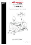
MUSCLE CHART
Targeted muscle groups:
The exercise routine that is performed on this product will develop primarily lower body muscle groups.
groups are shown in gray color on the chart below.
MUSCLE GROUPS
A
Shoulder muscles
B
Pectoral muscles
C
Bicep muscle
D
Abdominal muscles
E
Forearm muscles
F
Quadricep muscles
36
Calf muscles
G
Trapezius muscles
H
Tricep muscles
I
Back muscles
J
Gluteal muscles
K
Hamstring muscles
L
These muscle
STRETCHING ROUTINE
Warm up and cool down:
A successful exercise program consists of a warm-up, aerobic exercise, and a cool-down. Do the entire program at least two and
preferably three times a week, resting for a day between workouts. After several months, you can increase your workouts to four or
five times per week.
Warming up is an important part of your workout, and should begin every session. It prepares your body for more strenuous
exercise by heating up and stretching out your muscles, increasing your circulation and pulse rate, and delivering more oxygen to
your muscles. At the end of your workout, repeat these exercises to reduce sore muscle problems. We suggest the warm-up and
cool-down exercises on the following pages:
Toe Touch:
Slowly bend forward from
your waist, letting your back
and shoulders relax as you
stretch toward your toes.
Reach down as far as you
can and hold for 15 counts.
Shoulder Lift:
Lift your right shoulder up
toward your ear for one
count. Then lift your left
shoulder up for one count as
you lower your right shoulder.
Inner Thigh Stretch:
Sit with the soles of your feet
together with your knees
pointing outward. Pull your
feet as close into your groin
as possible. Gently push
your knees towards the floor.
Hold for 15 counts.
Hamstring Stretch:
Sit with your right leg
extended. Rest the sole of
your left foot against your
right inner thigh. Stretch
toward your toe as far as
possible. Hold for 15
counts. Relax and then
repeat with left leg extended.
Side Stretch:
Open your arms to the side
and continue lifting them until
they are over your head.
Reach your right arm as far
upward toward the ceiling as
you can for one count. Feel
the stretch up your right side.
Repeat this action with your
left arm.
Calf-Achilles Stretch:
Lean against a wall with your
left leg in front of the right and
your arms forward. Keep your
right leg straight and the left
foot on the floor; then bend
the left leg and lean forward
by moving your hips toward
the wall. Hold, and then
repeat on the other side for
15 counts.
Head Roll:
Rotate your head to the right
for one count, feeling the
stretch up the left side of your
neck. Next, rotate your
head back for one count,
stretching your chin to the
ceiling and letting your mouth
open. Rotate your head to
the left for one count, and
finally, drop your head to your
chest for one count.
37
STRETCHING ROUTINE
Read carefully the following before using your bike
♦
♦
♦
♦
Always stretch your muscles before exercise program. Warm up slowly by walking at a slow speed. Increase workout
intensity gradually until you reach your desired workout pace. Decrease workout intensity gradually to an easy walk, allowing
your heart rate to decrease to a normal situation.
When starting the bike, always stand with both feet on the step-on side rails.
When finishing, allow the running belt to slow down and come to a complete stop before stepping off.
Wear comfortable, non-restrictive clothing when using the bike. Never wear anything loose, such as baggy sweat pants,
neckties, loose socks or jewelry. Never drape towels on or around the bike during use.
WARNING
If you feel dizzy, nausea, chest pain or other abnormal symptoms, stop immediately. Consult a physician before continuing use.
AVERTISSEMENT: Si vous vous sentez étourdi, la nausée, la douleur de coffre ou d'autres symptômes anormaux, s'arrêtent
immédiatement. Consultez un médecin avant de continuer l'utilisation.
♦
♦
♦
Always use the handrail when stepping on or off the bike and when changing incline or speed.
This bike is equipped wit h a safety key – always clip the cord attached to the safety key to a part of your clothing so the safety
key will properly detach from the computer console, thereby stopping the bike.
Wear running or walking shoes with high-traction soles. To avoid injury and unnecessary wear on your bike, be sure your
shoes are free of any debris such as gravel and small rocks.
Before completing an exercise session, always:
1. Allow time to slow your pace, cool down, and reduce your heart rate to a normal level before completing your workout.
2. Grasp the handlebars and press the Speed “?” button. Slow your pace to an easy walk.
3. Ensure the running belt has come to a complete stop before exiting the bike.
WARNING
Turn off and unplug the bike before proceeding with any maint enance or visual inspections. Failure to do so may result in serious
injury. Note: Failure to perform the required periodic and preventative maintenance can void your warranty.
AVERTISSEMENT
Arrêtez et débranchez le tapis roulant avant de procéder à tout l'entretien ou inspections visuelles. Le manque de faire ainsi peut
avoir comme conséquence des dommages sérieux. Note : Le manque d'exécut er l'entretien périodique et préventif exigé peut vider
votre garantie.
At the end of every exercise session, always:
1. Remove the Safety Key from the computer console.
2. Use the master power switch to turn the bike off. The master power switch is located at the right side of frame next to the
electrical cord.
3. Always position and store the electrical cord where is clear from all pathways.
4. Unplug the electrical cord from the electrical outlet. This is especially important if you are not going to use your bike for
extended periods.
5. Wipe all bike surfaces with a dry cloth or towel es pecially perspiration on the handlebars, con troll panel, running belt or other bike
components.
38
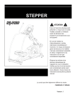
“PRODUCT PARTS DRAWING”
39
“PART LIST”
NO.
Item Name
Q'ty
NO.
Item Name
Q'ty
CE-8.0i-1 Main Frame
1
CE-8.0i-36 End Cap (50x100mm)
4
CE-8.0i-2 Front Stabilizer
1
CE-8.0i-37 Pulley (95mm)
1
CE-8.0i-3 Rear Stabilizer
1
CE-8.0i-38 Pulley (190mm)
1
CE-8.0i-4 Upright Post
1
CE-8.0i-39 Magnet
1
CE-8.0i-5 Stationary Handlebar
1
CE-8.0i-40 Belt (1059mm J6)
1
CE-8.0i-6 Left Upper Handlebar
1
CE-8.0i-41 Belt (960mm J8)
1
CE-8.0i-7 Right Upper Handlebar
1
CE-8.0i-42 Square Plug
1
CE-8.0i-8 Left Pivoting Arm
1
CE-8.0i-43 Console Fixed Bracket
1
CE-8.0i-9 Right Pivoting Arm
1
CE-8.0i-44 Front Aluminum Upright Cover
1
CE-8.0i-10 Left Pedal Support Arm
1
CE-8.0i-45 Back Aluminum Upright Cover
1
CE-8.0i-11 Right Pedal Support Arm
1
CE-8.0i-46 Upper Pivot Shaft Spacer
2
CE-8.0i-12 Front Left-Side Cover
1
CE-8.0i-47 Pedal Arm Spacer
2
CE-8.0i-13 Front Right-Side Cover
1
CE-8.0i-48 Linkage Spacer
4
CE-8.0i-14 Rear Left-Side Cover
1
CE-8.0i-49 Left Crank
1
CE-8.0i-15 Rear Right-Side Cover
1
CE-8.0i-50 Right Crank
1
CE-8.0i-16 Main Frame Base Cover
1
CE-8.0i-51 Crank Axle
1
CE-8.0i-17 Console
1
CE-8.0i-52 Mounting Plate
2
CE-8.0i-18 Console Bracket
1
CE-8.0i-53 Magnetic System
1
CE-8.0i-19 Console Lower Case
1
CE-8.0i-54 Motor
1
CE-8.0i-20 Battery Door
1
CE-8.0i-55 Cable
1
CE-8.0i-21 Front Decorating Upright Cover
1
CE-8.0i-56 Drive Shaft
1
CE-8.0i-22 Upright Sleeve
1
CE-8.0i-57 Bearing Stand
1
CE-8.0i-23 Accessory Tray
1
CE-8.0i-58 Leveler
5
CE-8.0i-24 Pulse Sensor Top Housing
2
CE-8.0i-59 Pedal Support Arm Connector
2
CE-8.0i-25 Pulse Sensor Bottom Housing
2
CE-8.0i-60 Bearing (6004)
12
CE-8.0i-26 Pulse Sensor Plate Assembly
4
CE-8.0i-61 Bearing (6905)
4
CE-8.0i-27 Foam Grip Assembly (40mm)
2
CE-8.0i-62 Eye Bolt
2
Stationary Handlebar Plug
CE-8.0i-28
(ψ31.8mm)
2
CE-8.0i-63 Tension Bracket
2
CE-8.0i-29 Foam Grip Assembly (225mm)
2
CE-8.0i-64 C Ring
3
CE-8.0i-30 Inner Rotator Cuff-Pivoting Arm
2
CE-8.0i-65 Square Key
1
CE-8.0i-31 Front Rotator Cuff-Pivoting Arm
2
CE-8.0i-66 Lock Washer (M8)
25
CE-8.0i-32 Back Rotator Cuff-Pivoting Arm
2
CE-8.0i-67 Washer (8x26x2.0t)
2
CE-8.0i-33 Pedal Upper Case
2
CE-8.0i-68 Washer (8x23x2.0t)
1
CE-8.0i-34 Non-Slip Pad
2
CE-8.0i-69 Washer (8x30x2.0t)
2
CE-8.0i-35 Transportation Wheel
2
CE-8.0i-70 Washer (8×38×2.0t)
4
40
PART LIST”
NO.
Item Name
Q'ty
NO.
Item Name
Q'ty
CE-8.0i-71 Washer (10×23×2.0t)
2
CE-8.0i-103 Nylon lock Nut (M10×p1.5×8t)
4
CE-8.0i-72 Washer (21×30×1.0t)
5
CE-8.0i-104 Nylon lock Nut (M10×p1.5)
2
2
CE-8.0i-105 Nut Cap (M17)
2
CE-8.0i-74 Screw (M3×10mm)
1
CE-8.0i-106 Adaptor
1
CE-8.0i-75 Screw (M4×20mm)
4
CE-8.0i-107 Sensor Wire & Stand
1
CE-8.0i-76 Screw (M5×18mm)
17
CE-8.0i-108 Upper Connection Wire
1
CE-8.0i-109 Middle Connection Wire
1
CE-8.0i-110 Lower Connection Wire
1
CE-8.0i-111 Upper Pulse Sensor Wire
1
CE-8.0i-112 Middle Pulse Sensor Wire
1
CE-8.0i-113 Lower Pulse Sensor Wire
2
CE-8.0i-73
CE-8.0i-77
Hex Socket Cap Screw
(M8×1.25×10mm)
Bolt, Button Head
(M6×p1.0×12mm)
2
CE-8.0i-78 Bolt, Button Head (35mm)
2
CE-8.0i-79 Screw, Round Head (M3×35mm)
4
CE-8.0i-80
CE-8.0i-81
CE-8.0i-82
CE-8.0i-83
CE-8.0i-84
CE-8.0i-85
CE-8.0i-86
CE-8.0i-87
CE-8.0i-88
CE-8.0i-89
CE-8.0i-90
Screw, Round Head
(M5×p0.8×15mm)
Screw, Round Head
(M5×p0.8×50mm)
Screw, Round Head
(M5×p0.8×75mm)
Bolt, Socket Head
(M8×p1.25×10mm)
Bolt, Socket Head
(M8×p1.25×65mm)
Bolt, Socket Head
(M8×p1.25×75mm)
Bolt, Socket Head
(M8×p1.25×100mm)
Bolt, Button Head
(M8×p1.25×12mm)
Bolt, Button Head
(M8×p1.25×16mm)
Bolt, Button Head
(M10×p1.5×45mm)
Bolt, Button Head
(M10×p1.5×85mm)
20
2
2
2
2
8
CE-8.0i-116 Lock Washer (M6)
2
2
CE-8.0i-117 Washer (6x19x2.0t)
2
CE-8.0i-118 Nut (3/8'')
5
CE-8.0i-119 Adaptor Wire
1
2
2
4
16
2
2
4
CE-8.0i-92 Bolt, Hex Head (M8×p1.25×15mm)
1
Thin Bolt, Hex Head
(M8×p1.25×15mm)
Bolt, Socket Head
(M6×p1.0×15mm)
CE-8.0i-115 Handheld Dome Plug
CE-8.0i-91 Carriage Bolt (M8×p1.25×75mm)
CE-8.0i-93
CE-8.0i-114
4
CE-8.0i-94 Bolt, Hex Head (M8×p1.25×65mm)
4
CE-8.0i-95 Bolt, Hex Head (M10×p1.5×50mm)
2
CE-8.0i-96 Flange Nut (M10×p1.25)
1
CE-8.0i-97 Nut (M10×p1.25)
1
CE-8.0i-98 Nut (M3)
4
CE-8.0i-99 Nut (M8×p1.25)
9
CE-8.0i-100 Nylon lock Nut (M6×p1.0)
2
CE-8.0i-101 Nylon lock Nut (M8×p1.25×6.2t)
4
CE-8.0i-102 Nylon lock Nut (M8×p1.25)
8
41
LIMITED WARRANTY
991214(1)
LIMITED HOME USE WARRANTY – SMOOTH FITNESS Bikes Warranty
Warranty Coverage: EVO Fitness and Smooth Fitness, Inc. ("Smooth Fitness") w arrants to the original ow ner that each new product to be free from defects
in w orkmanship and material, under normal use and conditions.
Period of Coverage: The Warranty on this product runs from the date of original purchase using the follow ing schedule:
Model Name
CE8.0LCi U.S.A. Only
CE8.0LCi Canada
Frame
Lifetime
Lifetime
Brake
Lifetime
Lifetime
Parts & Electronics
10 years
10 years
Labor
2 year
1 year
Labor: Smooth Fitness w ill reimburse for labor costs for Two (2) years. Smooth Fitness reserves the right to either:
Hire and reimburse an independent service technician w ho will come into the home for the repair,
OR
In the event that there is not an available certified Smooth Fitness service technician, Smooth w ill send the part directly to the consumer and w ill pay $75 US
per occurrence for the labor costs of such repair. If multiple repair attempts must be made for one reported problem, Smooth w ill only reimburse once per
occurrence.
Smooth Fitness reserves the right to inspect damaged parts for misuse. Your Original Receipt is proof of purchase and should be kept w ith the product
manual. You may be required to show proof of purchase prior to warranty service being initiated.
Remedy Provided by Smooth Fitness: Smooth Fitness will provide a replacement part free of charge if a defect is found during the Warranty period. Smooth
Fitness may at its discretion, choose to provide any of follow ing parts or repair options. In the event that a part is determined in need of replacement, upon
receipt of the part by Smooth Fitness, Smooth Fitness may send out the part by UPS ground or another such carrier directly to the customer’s home.
Any redemption may be by repair or replacement of the affected parts and/or product at the sole discretion of Smooth Fitness, by personnel approved by
Smooth Fitness.
Parts repaired or replaced pursuant to this Warranty shall be warranted for the unexpired portion of the Warranty applying to the original product. Any technical
advice furnished before or after delivery in regard to the use or application of Smooth Fitness products is furnished without charge and on the basis that it
represents Smooth Fitness' best judgment under the circumstances but that the advice is used at your sole risk.
Procedure for Obtaining Your Remedy Under This Warranty: To obtain service on a Smooth Fitness product, call Smooth Fitness. In the instance that
service is not available in an area, Smooth Fitness, at its discretion, can either 1) find a service technician in your area to perform w arranty service, 2) have a
local dealer perform warranty service, or 3) send the warranty parts to you and reimburse as described above. To help the technician assis t you, please have
the follow ing information ready:
•
Model name or number from the cover of the manual;
•
Serial number located on the frame of the unit; and
•
The part description and the order number.
Lim itations on Warranty: This Warranty does not cover any problems, damages or failures that are caused by accident, improper assembly, failure to
observe cautionary labels on the product, failure to operate the product correctly, power grid failures or spikes from your local electricity provider, abuse or
freight damage. Smooth Fitness does not w arrant against any damage or defects that may result from repair or alterations made to the product by an
unauthorized repair facility. In order for this w arranty to be valid, all Smooth Fitness and EVO Fitness exercise equipment must be stored and used in a fully
finished and livable room w ithin the residence (not including an indoor sw imming pool room).
This Warranty shall terminate if you sell or otherw ise transfer this product. This Warranty does not apply to any product shipped or handled outside of the
United States or Canada. This Warranty does not apply if the product is used as a rental product or in commercial use. Consequential and incidental damages
are not recoverable under this Warranty. (Some states do not allow
the exclusion or limitation of incidental or consequential damages, so the above limitation or exclusion may not apply to you.)
THIS WARRANTY IS EXPRESSLY IN LIEU OF ALL OTHER EXPRESS WARRANTIES. ALL IMPLIED WARRANTIES,
INCLUDING WARRANTIES OF MERCHANTABILITY OR FITNESS FOR ANY PARTICULAR PURPOSE, ARE LIMITED IN DURATION TO TWO (2) YEARS
FROM THE EFFECTIVE DATE OF THIS WARRANTY. SMOOTH FITNESS IS NOT
LIABLE FOR CONSEQUENTIAL OR INCIDENTAL DAMAGES RESULTING FROM ANY DEFECT IN PARTS NOR FOR
ANY BREACH OF EXPRESS OR IMPLIED WARRANTIES. SMOOTH FITNESS' SOLE LIABILITY UNDER THIS
WARRANTY IS LIMITED TO THE TERMS DESCRIBED IN THIS FORM. THIS WARRANTY GIVES YOU SPECIFIC LEGAL
RIGHTS, AND YOU MAY ALSO HAVE OTHER RIGHTS WHICH VARY FROM STATE TO STATE.
*Tw o year labor is valid only w ith the continental United States; Canadian labor w arranties are valid for the period of 1 year from date of purchase.
FORM WS-1 (rev. 03/2008)
42
Smooth Fitness
th
780 5 Ave
King of Prussia, PA 19406
Toll Free Customer Service:
1.888.800.1167
Website:
www.smoothfitness.com
43
44