1
NEXT - Warranty Statement
BACK - Intro
NEXT - Equipment Checklist
Limited Warranty
Limited Warranty Statement: SMC Networks, Inc. ("SMC") warrants its products to be free from defects in
workmanship and materials, under normal use and service, for the applicable warranty term. All SMC products
carry a standard 90-day limited warranty from the date of purchase from SMC or its Authorized Reseller. SMC
may, at its own discretion, repair or replace any product not operating as warranted with a similar or
functionally equivalent product, during the applicable warranty term. SMC will endeavor to repair or replace
any product returned under warranty within 30 days of receipt of the product.
The standard limited warranty can be upgraded to a Limited Lifetime* warranty by registering new products
within 30 days of purchase from SMC or its Authorized Reseller. Registration can be accomplished via the
enclosed product registration card or online via the SMC website. Failure to register will not affect the standard
limited warranty. The Limited Lifetime warranty covers a product during the Life of that Product, which is
defined as the period of time during which the product is an "Active" SMC product. A product is considered to
be "Active" while it is listed on the current SMC price list. As new technologies emerge, older technologies
become obsolete and SMC will, at its discretion, replace an older product in its product line with one that
incorporates these newer technologies. At that point, the obsolete product is discontinued and is no longer an
"Active" SMC product. A list of discontinued products with their respective dates of discontinuance can be
found at:
http://www.smc.com/index.cfm?action=customer_service_warranty
All products that are replaced become the property of SMC. Replacement products may be either new or
reconditioned. Any replaced or repaired product carries either a 30-day limited warranty or the remainder of
the initial warranty, whichever is longer. SMC is not responsible for any custom software or firmware,
configuration information, or memory data of Customer contained in, stored on, or integrated with any
products returned to SMC pursuant to any warranty. Products returned to SMC should have any customerinstalled accessory or add-on components, such as expansion modules, removed prior to returning the product
for replacement. SMC is not responsible for these items if they are returned with the product.
Customers must contact SMC for a Return Material Authorization number prior to returning any product to
SMC. Proof of purchase may be required. Any product returned to SMC without a valid Return Material
Authorization (RMA) number clearly marked on the outside of the package will be returned to customer at
customer's expense. For warranty claims within North America, please call our toll-free customer support
number at (800) 762-4968. Customers are responsible for all shipping charges from their facility to SMC. SMC
is responsible for return shipping charges from SMC to customer.
WARRANTIES EXCLUSIVE: IF AN SMC PRODUCT DOES NOT OPERATE AS WARRANTED ABOVE,
CUSTOMER’S SOLE REMEDY SHALL BE REPAIR OR REPLACEMENT OF THE PRODUCT IN QUESTION, AT SMC’S
OPTION. THE FOREGOING WARRANTIES AND REMEDIES ARE EXCLUSIVE AND ARE IN LIEU OF ALL OTHER
WARRANTIES OR CONDITIONS, EXPRESS OR IMPLIED, EITHER IN FACT OR BY OPERATION OF LAW,
STATUTORY OR OTHERWISE, INCLUDING WARRANTIES OR CONDITIONS OF MERCHANTABILITY AND
FITNESS FOR A PARTICULAR PURPOSE. SMC NEITHER ASSUMES NOR AUTHORIZES ANY OTHER PERSON TO
ASSUME FOR IT ANY OTHER LIABILITY IN CONNECTION WITH THE SALE, INSTALLATION, MAINTENANCE OR
USE OF ITS PRODUCTS. SMC SHALL NOT BE LIABLE UNDER THIS WARRANTY IF ITS TESTING AND
EXAMINATION DISCLOSE THE ALLEGED DEFECT IN THE PRODUCT DOES NOT EXIST OR WAS CAUSED BY
CUSTOMER'S OR ANY THIRD PERSON'S MISUSE, NEGLECT, IMPROPER INSTALLATION OR TESTING,
UNAUTHORIZED ATTEMPTS TO REPAIR, OR ANY OTHER CAUSE BEYOND THE RANGE OF THE INTENDED
USE, OR BY ACCIDENT, FIRE, LIGHTNING, OR OTHER HAZARD. LIMITATION OF LIABILITY: IN NO EVENT,
WHETHER BASED IN CONTRACT OR TORT (INCLUDING NEGLIGENCE), SHALL SMC BE LIABLE FOR
INCIDENTAL, CONSEQUENTIAL, INDIRECT, SPECIAL, OR PUNITIVE DAMAGES OF ANY KIND, OR FOR LOSS
OF REVENUE, LOSS OF BUSINESS, OR OTHER FINANCIAL LOSS ARISING OUT OF OR IN CONNECTION WITH
THE SALE, INSTALLATION, MAINTENANCE, USE, PERFORMANCE, FAILURE, OR INTERRUPTION OF ITS
PRODUCTS, EVEN IF SMC OR ITS AUTHORIZED RESELLER HAS BEEN ADVISED OF THE POSSIBILITY OF SUCH
DAMAGES. SOME STATES DO NOT ALLOW THE EXCLUSION OF IMPLIED WARRANTIES OR THE LIMITATION
OF INCIDENTAL OR CONSEQUENTIAL DAMAGES FOR CONSUMER PRODUCTS, SO THE ABOVE LIMITATIONS
AND EXCLUSIONS MAY NOT APPLY TO YOU. THIS WARRANTY GIVES YOU SPECIFIC LEGAL RIGHTS, WHICH
MAY VARY FROM STATE TO STATE. NOTHING IN THIS WARRANTY SHALL BE TAKEN TO AFFECT YOUR
STATUTORY RIGHTS.
* SMC will provide warranty service for one year following discontinuance from the active SMC price list. Under
the limited lifetime warranty, internal and external power supplies, fans, and cables are covered by a standard
one-year warranty from date of purchase.
SMC Networks, Inc.
38 Tesla
Irvine, CA 92618
Copyright
Information furnished by SMC Networks, Inc. (SMC) is believed to be accurate and reliable. However, no
responsibility is assumed by SMC for its use, nor for any infringements of patents or other rights of third parties
which may result from its use. No license is granted by implication or otherwise under any patent or patent
rights of SMC. SMC reserves the right to change specifications at any time without notice.
Copyright © 2002 by
SMC Networks, Inc.
38 Tesla
Irvine, California 92618
All rights reserved.
Trademarks
SMC is a registered trademark; and EZ Connect and EZ Hub are trademarks of SMC Networks, Inc. Other
product and company names are trademarks or registered trademarks of their respective holders.
BACK - Warranty Statement
NEXT - Install Instructions
Equipment Checklist
After unpacking the EZ Connect Wireless AP, check the contents of the box to be sure you have received the
following components:
•
•
•
•
1 EZ Connect Wireless Access Point (SMC2655W)
1 5 VDC power adapter
1 Driver, Utility, and Documentation CD-ROM
This User Guide
Immediately inform your dealer in the event of any incorrect, missing or damaged parts. If possible, please
retain the carton and original packing materials in case there is a need to return the product.
The EZ Connect Wireless Access Point is covered by a limited lifetime warranty.
Complete warranty information for all SMC products is available on SMC's Web site at www.smc.com
BACK - Equipment Checklist
NEXT - Utility Installation
SMC2655W: Installation Instructions
1) Site Location – Choose a location for your SMC2655W Wireless Access Point. Usually, the best location is
at the center of your wireless coverage area, if possible within line-of-sight of all wireless devices.
2) Placement - Put the Access Point in a position that gives it maximum coverage. Normally, the higher you
place the antenna, the better the performance.
3) Connect the Ethernet cable – The SMC2655W can be wired to an Ethernet network through an Ethernet
device such as a hub or a switch using category 3, 4, or 5 UTP Ethernet cable and an RJ-45 connector.
4) Connect the power cable – Connect the power adapter cable to the 5 VDC power socket on the rear
panel.
Warning: Use only the power adapter supplied with the SMC2655W.
BACK - Install Instructions
NEXT - Application-based AP Configuration
Utility Installation
Windows 98/NT/Me/2000/XP
This section will describe the process for installing the utility program for your SMC2655W Access Point.
Step 1: Insert the Utility and Documentation CD.
Step 2: Double-click the "My Computer" icon your desktop and browse to your CD-ROM drive. (Note: In most
cases, the letter of your CD-ROM drive is D.)
Step 3: Open the Utility folder and run the [Setup.exe] file. The following will appear:
Figure 1.0
Step 4: You will be given the option to choose the location where the Configuration Utility will be installed. It
is recommended to leave this at the default value. Click [Next >] to continue.
Figure 1.1
Step 5: You will be given the option to choose the folder name for the Utility program. It is recommended to
leave this at the default value. Click [Next >] to continue.
Figure 1.2
Step 6: The wizard will finalize the installation.
Figure 1.3
Step 7: Once the files are installed, you will be given the option of adding a shortcut to the utility in your
startup folder. If you click [Yes], Windows will automatically run the utility upon boot up. If you click [No], you
will need to browse through the Start Menu in order to run the application.
Figure 1.4
Figure 1.5
BACK - Utility Installation
NEXT - Web-based Configuration
Utility Configuration (Application-based)
Once you have completed the installation procedure outlined in the [Utility Installation] section of this manual,
you can follow the steps below to run the utility program.
Click the [Start] button, go to the [Programs] folder and click [EZ Connect Wireless AP Utility].
Figure 1.0
Then click the [EZ Connect 11Mbps Wireless Access Point Utility] icon and you should see the following appear
on your screen:
Figure 1.1
The utility will automatically scan for your AP. If you do not see the "MiniAP" in the drop down menu, please
select the [Browse Again] option from the drop down menu. Then enter the word "default" (all lowercase) for
the password. This is the factory default password for the Access Point. Then press [Login] to continue.
Figure 1.2
The screen in Figure 1.2 shows you the information that is currently set on the AP. The default SSID is
"WLAN", the default IP address is 192.168.2.50 and the default gateway is 192.168.2.1. This is very important
information to note when configuring your wireless network so that it is integrated properly with your existing
network. For instance, if your existing LAN is operating on a 10.0.0.1 IP scheme, then you should change the
IP address of the Access Point to 10.0.0.x (where x is not equal to 1 and is less than 255). To change these
configuration settings, simply click the [Setup] button.
Figure 1.3
Now you can manually specify the IP of your Access Point, the subnet mask, and its gateway. You can also
change the SSID to the desired workgroup name and you can change the channel to a specific frequency to
avoid wireless interference from other nearby devices.
If you select the [Security] option shown below the AP Name, you will see the following screen:
Figure 1.4
After clicking [Setup], you can enable MAC address control or manage the Wired Equivalent Privacy (WEP)
security key. You simply need to select the [WEP 64bit] or [WEP 128bit] options in order to activate the desired
encryption. You must manually enter the key.
The SMC2655W Access Point supports Wired Equivalent Privacy (WEP) in order to secure your wireless network
and prevent unauthorized access. For more secure data transmissions, set encryption to "128-bit" or "64-bit".
The 128-bit setting gives a higher level of security. The setting must be the same for all clients in your wireless
network. By default, the WEP is disabled.
Figure 1.5
Figure 1.6
For HEX (0-9, A-F) "Key Format", the security is enabled by entering 10-digit keys for the 64-bit WEP
configuration, and 26-digit keys for a 128-bit WEP configuration. For ASCII "Key Format", the security is
enabled by entering 5-letter keys for 64-bit WEP, and 13-letter keys for 128-bit WEP.
Note that there are 4 different keys to choose from. Choose the Key that has the encryption string you prefer.
The wireless clients must be configured in this same fashion.
Figure 1.7
The MAC address filtering section, you can decide which wireless devices are allowed to connect to the Access
Point by adding the MAC address of the allowed clients. Wireless devices that are not in the table will be
effectively denied access. You can enter a maximum of 32 addresses.
Check the [Enable MAC access control] option, and enter the MAC address of the allowed clients. The format is
12 hexadecimal digits (e.g. - 0050BACA6BBC). After you have finished entering the address, click the [ADD]
button. Then press the [Apply] button in the bottom right-hand corner to activate the MAC Filtering.
To view the utility version or firmware version, you can go to the [About] section.
Figure 1.8
The table below shows all the default values for this AP:
Setting
AP Name
SSID
Channel
IP Address
Subnet Mask
Gateway
Encryption
MAC Access Control
Password
Default Value
MiniAP
WLAN
1
192.168.2.50
255.255.255.0
192.168.2.1
Disabled
Disabled
default
BACK - Application-based Configuration
NEXT - Firmware Update Procedure
Utility Configuration (Web-based)
The default IP address of the SMC2655W is 192.168.2.50. If you prefer to configure the AP via a web browser
rather than the utility program, you can do so by opening your web browser and going to
"http://192.168.2.50". You need to be sure that your computer is configured in the same subnet in order to
access the Access Point's web management interface. For example, your machine's IP should be 192.168.2.x
(where x is not equal to one (1) or fifty (50), but is less than 255).
Once you are able to access the AP, you will need to login by entering the default password. Type in "default"
and then press [Login].
Figure 1.0
Once you are logged in, you will be able to view the firmware version, change the IP scheme, change the
password and/or configure security options.
Figure 1.1
Click the [Configuration] link on the left and a drop down menu will appear on the page. Then click the
[General] option to continue. The "Access Point Name" is simply used to identify the AP. This is not the Service
Set Identifier.
The "ESSID" field represents the wireless workgroup name. Your wireless clients must have the same value
configured in their network settings. You can also choose the operating radio channel. In the "Administration
Parameters" section, you can change the password required for any administrator to log into this AP. Note that
this password is needed to login via both the web interface and the utility application. After changing any
parameters, you need to press the [Apply] button on the bottom of the page.
Figure 1.2
Click the [WEP] link on the left in order to access the 64/128-bit encryption configuration.
For HEX (0-9, A-F) "Key Format", the security is enabled by entering 10-digit keys for the 64-bit WEP
configuration, and 26-digit keys for a 128-bit WEP configuration. Be sure to type "0x" before entering the HEX
key. For ASCII "Key Format", the security is enabled by entering 5-letter keys for 64-bit WEP, and 13-letter
keys for 128-bit WEP.
Note that there are 4 different keys to choose from. Choose the Key that has the encryption string you prefer.
The wireless clients must be configured in this same fashion.
Figure 1.3
Click the [Access Control] link on the left in order to access and configure the MAC Address List. In the field on
the right, enter the new MAC address of a client that will be allowed to access the network. The format is 12
hexadecimal digits with colons separating each pair of digits (e.g. - 00:50:BA:CA:6B:BC).
Then click the [Add] button. The page will be refreshed and the MAC address you entered will appear in the
"Address List". Make sure the "Enable" radio button is selected and click the [Apply] button. (Note: The MAC
Address Filtering will not take effect until the "Enable" radio button is selected)
Figure 1.4
Click the [TCP/IP] link on the left and then click [General] to view the current IP configuration of the Access
Point. You can manually enter new IP info as well in order to easily integrate the unit into your existing LAN.
Then press the [Apply] button to save your changes.
Figure 1.5
BACK - Web-based Configuration
NEXT - Frequently Asked Questions
Firmware Update Procedure
Once you have completed the installation procedure outlined in the [Utility Installation] section of this manual,
you can follow the steps below to run the firmware upgrade utility program.
Click the [Start] button, go to the [Programs] folder and click [EZ Connect Wireless AP Utility].
Figure 1.0
Then click the [Firmware Upgrade Utility] icon and you should see the following appear on your screen:
Figure 1.1
Enter the administrator password in order to log into the Access Point. Then you will see the details of the
current firmware. Click the [Open File] button, browse to the folder containing the latest firmware revision, and
open it. Then compare the details under the "current version" and "new version" sections to be sure that you
are in fact upgrading the firmware to a more recent revision. Once you are sure you have the correct upgrade
file, click the [Upgrade] button and the firmware update process will begin.
The status bar will show the level of completion.
Figure 1.2
Restore to Factory Defaults Procedure
1) Locate the [Default] button on the back of the SMC2655W Access Point.
2) Unplug the power from the back of the AP for 10 seconds.
3) Depress the [Default] button for 3 seconds.
4) Plug the power connector into the AP while depressing the [Default] button.
5) Release the [Default] button after 3 seconds. Wait 3 seconds and then depress the [Default] button again.
6) The "LNK/ACT" and "TX/RX" LEDs will blink once per second about 10-12 times. Release the [Default]
button when these LEDs begin flashing rapidly.
BACK - Firmware Update Procedure
NEXT - Glossary
Troubleshooting / FAQs
If mobile users do not have roaming access to the SMC2655W access point:
Make sure that all the SMC2655Ws and stations in the ESS in which the WLAN mobile users can roam are
configured to the same WEP setting, SSID, and authentication algorithm.
If you forgot your password or your SMC2655W has locked up, you can reset it to factory defaults
by performing the following steps:
1) Locate the [Default] button on the back of the SMC2655W Access Point.
2) Unplug the power from the back of the AP for 10 seconds.
3) Depress the [Default] button for 3 seconds.
4) Plug the power connector into the AP while depressing the [Default] button.
5) Release the [Default] button after 3 seconds. Wait 3 seconds and then depress the [Default] button again.
6) The "LNK/ACT" and "TX/RX" LEDs will blink once per second about 10-12 times. Release the [Default] button
when these LEDs begin flashing rapidly.
What is a Wireless LAN?
A local area network that transmits over the air typically in an unlicensed frequency such as the 2.4GHz band. A
wireless LAN does not require lining up devices for line of sight transmission like IrDA. Wireless access points
(base stations) are connected to an Ethernet hub or server and transmit a radio frequency over an area of
several hundred to a thousand feet which can penetrate walls and other non-metal barriers. Roaming users can
be handed off from one access point to another like a cellular phone system. Laptops use wireless network
cards that plug into an existing PCMCIA slot or that are self contained on PC cards, while stand-alone desktops
and servers use plug-in cards (ISA, PCI, etc.).
What is AD-HOC?
An AD-HOC network is a peer to peer network where all the nodes are wireless clients. As an example, two PC’s
with wireless adapters can communicate with each other as long as they are within range. A wireless extension
point can extend the range of an AD-HOC network.
What is the 802.11 standard?
A family of IEEE standards for wireless LANs first introduced in 1997. 802.11 provides 1 or 2 Mbps transmission
in the 2.4GHz band using either a frequency hopping modulation (FHSS) technique or direct sequence spread
spectrum (DSSS), which is also known as CDMA. The 802.11b standard defines an 11 Mbps data rate in the
2.4GHz band, and the 802.11a standard defines 54 Mbps in the 5GHz band.
What is Infrastructure?
In order for your wireless components to interact with traditional wired networks they need a media bridge to
translate for them. This is where INFRASTRUCTURE or Network mode comes into play. An ACCESS POINT is
attached to the network using CAT-5 Ethernet cable attaching to a hub, switch or another PC. Wireless PC’s can
then communicate to Wired Ethernet computers through this access point. The total range of the network is
limited to a radius around this Access Point. To increase the range, extra Access Points may be wired into the
network. These Access Points talk to each other over the hard-wired Ethernet cables however, they cannot
communicate wirelessly to one another and they must be wired to the same network. Individual wireless PC’s
can move between Access Points on the same network seamlessly due to a feature called ROAMING.
What is Tx Rate?
Tx-Rate or TRANSFER RATE is the current speed at which the network component is operating. SMC-802.11b
products can operate at speeds of 1Mb, 2Mb, 5.5Mb, & 11Mbps. A wireless card set to AUTO will attempt to
connect at whatever speed will give the best throughput on the network.
What is RTS Threshold?
(Request To Send) An RS-232 signal sent from the transmitting station to the receiving station requesting
permission to transmit. RTS is a collision avoidance method used by all 802.11b wireless networking devices. In
most cases you will not need to activate or administer RTS. Only if you find yourself in an Infrastructure
environment where all nodes are in range of the Access Point but may be out of range of each other. It is
recommended to leave this setting at its default value leaving this feature disabled.
What is Authentication Algorithm?
Authentication Algorithm is the means by which one station is authorized to communicate with another. In an
Open System, any station can request authorization in accordance with the WECA standard. In a Shared key
system, only stations that possess a secret encrypted key may participate in the network. This is a low level
security key which allows the equipment with the shared key algorithm to see each other on the wireless lan.
What is DBI?
The ability of the antenna to shape the signal and focus it in a particular direction is called Antenna Gain, and is
expressed in terms of how much stronger the signal in the desired direction is, compared to the worst possible
antenna, which distributes the signal evenly in all directions (an Isotropic Radiator). To express the relationship
to the Isotropic reference, this is abbreviated: "dBi". The typical omni-directional "stick" antenna is rated at 6-8
dBi, indicating that that by redirecting the signal that would have gone straight up or down to the horizontal
level, 4 times as much signal is available horizontally. A parabolic reflector design can easily achieve 24 dBi.
What is WEP?
Short for Wired Equivalent Privacy, WEP is a security protocol for wireless local area networks (WLANs) defined
in the 802.11B standard.
WEP is designed to provide the same level of security as that of a wired LAN. LANs are inherently more secure
than WLANs because LANs are somewhat protected by the physicalities of their structure, having some or all
part of the network inside a building that can be protected from unauthorized access. WLANs, which are over
radio waves, do not have the same physical structure and therefore are more vulnerable to tampering.
WEP aims to provide security by encrypting data over radio waves so that it is protected as it is transmitted
from one end point to another. The Wired Equivalent Privacy (WEP) feature uses the RC4 PRNG algorithm
developed by RSA Data Security, Inc.
If your wireless access point supports MAC filtering, it is recommended that you use this feature in addition to
WEP (MAC filtering is much more secure than encryption).
Technical Specifications
Standards:
IEEE 802.11b compliant
IEEE 802.3 (10Base-T)
Wireless Data Rates:
1/2/5.5/11 Mbps
Data Modulation Techniques:
BPSK (1 Mbps), QPSK (2 Mbps), CCK (5.5/11 Mbps)
Operating Range:
Up to 825 ft
Radio Signal Type:
Direct Sequence Spread Spectrum (DSSS)
Media Access Protocol:
CSMA/CA (Collision Avoidance) with ACK
Security:
64/128-bit Wired Equivalent Privacy (WEP) MAC Address Filtering
RF Frequency:
2412 MHz - 2484
2412 MHz - 2462
2412 MHz - 2472
2457 MHz - 2462
2457 MHz - 2472
MHz
MHz
MHz
MHz
MHz
(Japan Band - 14 channels)
(North America - 11 channels)
(Europe - 13 channels)
(Spain - 2 channels)
(France - 4 channels)
Operating Channel:
11 Channels (US, Canada)
13 Channels (Europe)
14 Channels (Japan)
RF Output Power:
20 dBm
Sensitivity:
-82 dBm @ 11 Mbps
Operating Systems:
Windows 98/Me/NT/2000/XP
Network Management:
Web-based Interface
Utility (Access Point Manager) - Windows-based
Antenna Type:
External Dipole Antenna
LED Indicators:
Power/Status
GREEN: Power On
Wireless Tx/Rx
Green LED blinking: Tx/Rx activity Ethernet Tx/Rx
Green LED blinking: Tx/Rx activity
Power Voltage:
5 Volt DC
Dimensions:
117 x 62 x 22 mm
Environmental:
Operating: 10 to 65ºC
Storage: 30 to 70ºC
Humidity: 5-95% non-condensing
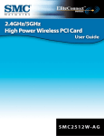
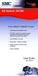
Wireless AP Maximum Distance Table
Important Notice – Maximum distances posted below are actual tested distance thresholds. However, there
are many variables such as barrier composition and construction, as well as local environmental interference
that may impact your actual distances and cause you to experience distance thresholds far lower than those
posted below. If you have any questions or comments regarding the features or performance of this product, or
if you would like information regarding our full line of wireless products, visit us on the web at www.smc.com,
or call us toll-free at 800.SMC.4YOU. SMC Networks stands behind every product sold with a 30-day satisfaction
guarantee and a limited-lifetime warranty.
SMC 802.11b Wireless AP Maximum Distance Table
Environmental
Condition
Outdoors: A line-ofsight
environment with no
interference or
obstruction
between the Access
Point
and users.
Indoors: A typical
office or
home environment with
floor to ceiling
obstructions
between the Access
Point
and users.
Speed and Distance Ranges
11 Mbps
5.5 Mbps
2 Mbps
1 Mbps
128 m
(422 ft)
152 m
(502 ft)
167 m
(551 ft)
250 m
(825 ft)
27 m
(90 ft)
31 m
(102 ft)
32.5 m
(107 ft)
33 m
(109 ft)
BACK – Frequently Asked Questions
NEXT - Featured Products
Glossary
10BaseT - Physical Layer Specification for Twisted-Pair Ethernet using Unshielded Twisted Pair wire at 10Mbps.
This is the most popular type of LAN cable used today because it is very cheap and easy to install. It uses RJ45 connectors and has a cable length span of up to 100 meters. There are two versions, STP (Shielded Twisted
Pair) which is more expensive and UTP (Unshielded Twisted Pair), the most popular cable. These cables come
in 5 different categories. However, only 3 are normally used in LANs, Category 3, 4 and 5. CAT 3 TP (Twisted
Pair) cable has a network data transfer rate of up to 10Mbps. CAT 4 TP cable has a network data transfer rate
of up to 16Mbps. CAT 5 TP cable has a network data transfer rate of up to 100Mbps.
Access Point - A device that is able to receive wireless signals and transmit them to the wired network, and
vice versa - thereby creating a connection between the wireless and wired networks.
Ad Hoc - An ad hoc wireless LAN is a group of computers, each with LAN adapters, connected as an
independent wireless LAN.
Adapter - A device used to connect end-user nodes to the network; each contains an interface to a specific
type of computer or system bus, e.g. EISA, ISA, PCI, PCMCIA, CardBus, etc.
Auto-Negotiation - A signaling method that allows each node to define its operational mode (e.g., 10/100 Mbps
and half/full duplex) and to detect the operational mode of the adjacent node.
Backbone - The core infrastructure of a network. The portion of the network that transports information from
one central location to another central location where it is unloaded onto a local system.
Base Station - In mobile telecommunications, a base station is the central radio transmitter/receiver that
maintains communications with the mobile radiotelephone sets within its range. In cellular and personal
communications applications, each cell or micro-cell has its own base station; each base station in turn is
interconnected with other cells' bases.
BSS - BSS stands for "Basic Service Set". It is an Access Point and all the LAN PCs that are associated with it.
CSMA/CA - Carrier Sense Multiple Access with Collision Avoidance
DHCP - Dynamic Host Configuration Protocol. This protocol automatically configures the TCP/IP settings of
every computer on your home network.
DNS - DNS stands for Domain Name System, which allows Internet host computers to have a domain name
(such as www.smc.com) and one or more IP addresses (such as 192.34.45.8). A DNS server keeps a database
of host computers and their respective domain names and IP addresses, so that when a domain name is
requested (as in typing " www.smc.com" into your Internet browser), the user is sent to the proper IP address.
The DNS server address used by the computers on your home network is the location of the DNS server your
ISP has assigned.
DSL - DSL stands for Digital Subscriber Line. A DSL modem uses your existing phone lines to transmit data at
high speeds.
Ethernet - A standard for computer networks. Ethernet networks are connected by special cables and hubs,
and move data around at up to 10 million bits per second (Mbps).
ESS - ESS (ESS-ID, SSID) stands for "Extended Service Set". More than one BSS is configured to become an
Extended Service Set. LAN mobile users can roam between different BSSs in an ESS (ESS-ID, SSID).
Fast Ethernet NIC - Network interface card that is in compliance with the IEEE 802.3u standard. This card
functions at the media access control (MAC) layer, using carrier sense multiple access with collision detection
(CSMA/CD).
Fixed IP – (see Static IP)
Full-Duplex - Transmitting and receiving data simultaneously. In pure digital networks, this is achieved with
two pairs of wires. In analog networks, or digital networks using carriers, it is achieved by dividing the
bandwidth of the line into two frequencies, one for sending, one for receiving.
Hub - Central connection device for shared media in a star topology. It may add nothing to the transmission
(passive hub) or may contain electronics that regenerate signals to boost strength as well as monitor activity
(active/intelligent hub). Hubs may be added to bus topologies; for example, a hub can turn an Ethernet
network into a star topology to improve troubleshooting.
IP Address - IP stands for Internet Protocol. An IP address consists of a series of four numbers separated by
periods, that identifies an single, unique Internet computer host. Example: 192.34.45.8.
ISP - Internet Service Provider. An ISP is a business that provides connectivity to the Internet for individuals
and other businesses or organizations.
LAN - A communications network that serves users within a confined geographical area. It is made up of
servers, workstations, a network operating system and a communications link. Servers are high-speed
machines that hold programs and data shared by network users. The workstations (clients) are the users'
personal computers, which perform stand-alone processing and access the network servers as required.
Diskless and floppy-only workstations are sometimes used, which retrieve all software and data from the
server. Increasingly, "thin client" network computers (NCs) and Windows terminals are also used. A printer can
be attached locally to a workstation or to a server and be shared by network users. Small LANs can allow
certain workstations to function as a server, allowing users access to data on another user's machine. These
peer-to-peer networks are often simpler to install and manage, but dedicated servers provide better
performance and can handle higher transaction volume. Multiple servers are used in large networks.
The message transfer is managed by a transport protocol such as TCP/IP and NetBEUI. The physical
transmission of data is performed by the access method (Ethernet, Token Ring, etc.), which is implemented in
the network adapters that are plugged into the machines. The actual communications path is the cable
(twisted pair, coax, optical fiber) that interconnects each network adapter.
MAC Address - MAC (Media Access Control) A MAC address is the hardware address of a device connected to a
network.
MDI / MDI-X - Medium Dependent Interface - Also called an "uplink port," it is a port on a network hub or
switch used to connect to other hubs or switches without requiring a crossover cable. The MDI port does not
cross the transmit and receive lines, which is done by the regular ports (MDI-X ports) that connect to end
stations. The MDI port connects to the MDI-X port on the other device. There are typically one or two ports on
a device that can be toggled between MDI (not crossed) and MDI-X (crossed).
Medium Dependent Interface – X (crossed) - A port on a network hub or switch that crosses the transmit lines
coming in to the receive lines going out.
NAT – (Network Address Translation) This process allows all of the computers on your home network to use
one IP address. The NAT capability of the Barricade, allows you to access the Internet from any computer on
your home network without having to purchase more IP addresses from your ISP. Network Address Translation
can be used to give multiple users access to the Internet with a single user account, or to map the local
address for an IP server (such as Web or FTP) to a public address. This secures your network from direct
attack by hackers, and provides more flexible management by allowing you to change internal IP addresses
without affecting outside access to your network. NAT must be enabled to provide multi-user access to the
Internet or to use the Virtual Server function.
Packet Binary Convulational Code(tm) (PBCC) - A modulation technique developed by Texas Instruments Inc.
(TI) that offers data rates of up to 22Mbit/s and is fully backward compatible with existing 802.11b wireless
networks.
PCI - Peripheral Component Interconnect - Local bus for PCs from Intel that provides a high-speed data path
between the CPU and up to 10 peripherals (video, disk, network, etc.). The PCI bus runs at 33MHz, supports
32-bit and 64-bit data paths, and bus mastering.
PPPoE - Point-to-Point Protocol over Ethernet. Point-to-Point Protocol is a method of secure data transmission
originally created for dial-up connections. PPPoE is for Ethernet connections.
Roaming - A function that allows your to move through a particular domain without losing network
connectivity.
Static IP - If your Service Provider has assigned a fixed IP address; enter the assigned IP address, subnet mask
and the gateway address provided by your service provider.
Subnet Mask - A subnet mask, which may be a part of the TCP/IP information provided by your ISP, is a set of
four numbers configured like an IP address. It is used to create IP address numbers used only within a
particular network (as opposed to valid IP address numbers recognized by the Internet.
TCP/IP - Transmission Control Protocol/Internet Protocol. This is the standard protocol for data transmission
over the Internet.
TCP - Transmission Control Protocol - TCP and UDP (User Datagram Protocol) are the two transport protocols
in TCP/IP. TCP ensures that a message is sent accurately and in its entirety. However, for real-time voice and
video, there is really no time or reason to correct errors, and UDP is used instead.
UDP - User Datagram Protocol - A protocol within the TCP/IP protocol suite that is used in place of TCP when a
reliable delivery is not required. For example, UDP is used for real-time audio and video traffic where lost
packets are simply ignored, because there is no time to retransmit. If UDP is used and a reliable delivery is
required, packet sequence checking and error notification must be written into the applications.
BACK – Glossary
NEXT - Technical Support
Featured Products
Thank you for purchasing SMC products! Users who have
purchased the SMC2655W have also purchased the following
devices:
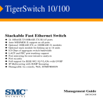
The Barricade™ Plus Cable/DSL Broadband Router (7004FW) is the ideal networking solution for both the
home and business user. Easily connect this router to the Internet in minutes using SMC’s new 3-Click Install
Wizard. This platform independent multi-function router combines a 4-port 10/100 Mbps dual-speed switch,
robust Stateful Packet Inspection (SPI) firewall, and Virtual Private Network (VPN) support into one convenient
product.
To complement the incorporated SPI firewall functions, the Barricade Plus Router has a built-in VPN tunnel that
supports IPSec and PPTP Client/Server connectivity. This VPN functionality is the perfect solution for remotely
accessing a network securely by establishing an authenticated and encrypted tunnel over the Internet. No
matter what connection you set up, you can be well assured that your data is being transmitted and
exchanged in the most secure manner. This integrated VPN connection is an ideal solution for both individuals
who telecommute from home or small offices that need to create a single VPN connection to securely connect
remote offices, but do not want the hassle of a confusing server set-up.
SMC’s family of USB products offers a convenient and cost-effective means of bringing straightforward
peripheral connectivity to the desktop based on the Universal Serial Bus (USB). These products feature true
plug-and-play connection of PC peripherals “outside the box” and mark a significant advance in desktop cable
management. Using the EZ Connect™ USB/Ethernet Converter you can simplify PC connections in the
home, office or on the road.
SMC’s EZ Switch™ 10/100s are dual-speed desktop network switches that are as easy to install and use as an
ordinary hub, with the added dimension of dramatically improving network performance by offering speeds up
to 200 Mbps per port. Moreover, the 5 port, SMC-EZ6505TX features Auto MDI/MDI-X on each port,
providing added functionality and ease of use.
Winner of PC Magazine’s Editor’s Choice Award, and voted among the magazine’s “Best of 2001” networking
products, the SMC TigerStack™ II 10/100 Managed Switch (SMC6624M) is an ultra-fast highperformance switch. This managed switch has a 24-fixed port design that supports auto-MDIX 10/100
connections with a non-blocking switch fabric of 9.6Gbps. For added functionality, the TigerStack II provides
two expansion slots that can support Gigabit copper, 100BASE-FX fiber, or 1000BASE-T/SX/LX fiber modules.
With the purchase of optional stacking kits, the TigerStack II can be stacked up to 16 units high, providing
easy management for up to 386 ports under a single IP address.
The SMC TigerStack II is the perfect switch to provide traffic security and an efficient use of network
bandwidth. It supports an integrated Web-based management configuration system that is easily accessed by
using any standard Web-browser. The TigerStack II’s management system supports advanced features
including port or protocol based tagged VLANs, automatic GVRP VLAN registration, QoS priority queuing for
real-time multimedia applications, IGMP to prevent flooding of IP multicast traffic, and LACP to facilitate linking
aggregation. By using this built-in management system, network managers can configure the switch to meet a
wide variety of networking requirements. To complement its management system, the switch also supports
advanced security features such as RMON traps or IP filtering to prevent unauthorized users’ access. Combine
these features with SMC’s support and service, and it’s not hard to see why the TigerStack II 10/100 is the
ideal solution for today’s networks.
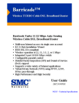
The Barricade™ Wireless Cable/DSL Broadband Router (SMC7004VWBR) is the ideal networking solution for
any home and business user. This platform independent multi-functional router combines a 4-port 10/100
Mbps dual-speed switch, an 802.11b wireless access point, Stateful Packet Inspection (SPI) firewall security,
network management, and Virtual Private Network (VPN) pass-through support into one convenient device.
The Wireless Barricade Router is the first router in its class to offer an integrated Stateful Packet Inspection
(SPI) firewall. This firewall provides protection against hacker invasions, such as Denial of Service (DoS)
attacks by analyzing individual data packets, as they pass through the Barricade, to ensure that only authorized
packets are allowed access to the network. To control network access, parents or business owners can block
certain web sites by entering either a URL address or just a keyword of the web site. In addition to these
incredible features, this latest addition to the Barricade family provides hacker prevention and logging
functionalities. For example, when a hacker attempts to access your network, the Barricade can alert you via
email so you can take appropriate action.
The Wireless Barricade provides a 10/100 Mbps WAN port for high-speed integration into your network.
Supporting NAT, the Barricade can provide simultaneous Internet access for up to 253 PCs using a single
purchased IP address. To manage these connections, the Barricade has a built-in DHCP server to auto-assign
IP addresses to devices on your network. To install this device, simply place the EZ 3-Click Installation CD into
your CD-ROM drive and in minutes you will be surfing the web. By using the web-based management system
you can configure this router to handle IP routing and port forwarding through the Virtual Server option. For
added management, this router also has a full- featured Access Control option. The integrated feature allows
you to filter traffic through your network based on IP and MAC address.
BACK – Featured Products
Technical Support
FOR TECHNICAL SUPPORT, CALL:
From U.S.A. and Canada (24/7)
(800) SMC-4-YOU; (949) 707-2400; (949) 707-2460 (Fax)
From Europe (8:00 AM - 5:30 PM UK Greenwich Mean Time)
44 (0) 1189 748740; 44 (0) 1189 748741 (Fax)
INTERNET
E-mail addresses:
[email protected]
Driver updates:
http://www.smc.com/index.cfm?action=tech_support_drivers_downloads
FOR LITERATURE OR ADVERTISING RESPONSE, CALL:
U.S.A. and Canada
Spain
UK
Southern Europe
Central/Eastern Europe
Nordic
Middle East:
South Africa
PRC
Taiwan
Asia Pacific
Korea
Japan
Australia
India
(800) SMC-4-YOU
34-93-477-4920
44 (0) 1189 748720
33 (1) 41.18.68.68
49 (0) 89 92861-200
46 (8) 564 33145
971-4818410
27 (0) 11-3936491
86-10-6235-4958
886-2-2747-4780
(65) 338 8916
82-2-553-0860
81-45-224-2332
61-2-9416-0437
91-22-8204437
Fax
Fax
Fax
Fax
Fax
Fax
Fax
Fax
Fax
Fax
Fax
Fax
Fax
Fax
Fax
(949) 707-2460
34-93-477-3774
44 (0) 1189 748701
33 (1) 41.18.68.69
49 (0) 89 92861-230
46 (8) 87 62 62
971-4817993
27 (0) 11-3936491
86-10-6235-4962
886-2-2747-9220
(65) 337 7391
82-2-553-7202
81-45-224-2331
61-2-9416-0474
91-22-8204443