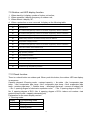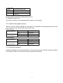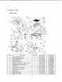
1
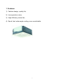
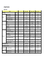
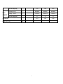
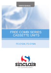
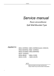
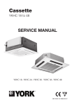
MULTI SPLIT TYPE, HEAT PUMP AIR CONDITIONERS
Technical service manual
R410A Cassette Inverter multi Series
Indoor Models
SMF-C09AI
SMF-C12AI
SMF-C18AI
Outdoor Models
SMF-4E27AI
1
CONTENTS
1. Features
2. Specification
3. Outline and dimension
4. Indoor unit combination
5. Capacity table
6. Wiring diagram
7. Electronic control functions
8. Exploded view
2
1. Features:
1) Fashion design, quality life;
2) Low operation noise;
3) High efficiency screw fan;
4) Equal, fast, wide-angle cooling, more comfortable.
3
2.Specification
indoor unit
SMF-C09AI
Model
Power supply
Capacity
Ph-V-Hz
SMF-C18AI
1Ph,220-240V~,50Hz
1Ph,220-240V~,50Hz
1Ph,220-240V~,50Hz
Cooling Capacity
BTU/h
9,000
12,000
18,000
Heating Capacity
BTU/h
11,000
13,000
20,500
Design Pressure (Hi/Lo)
Mpa
4.2/2.5
4.2/2.5
4.2/2.5
Max. Operating Pressure
Mpa
3.7
3.7
3.7
Model
YDK45-4F
YDK45-4F
YDK45-4F
Brand
Welling
Welling
Welling
W
80
80
80
Capacitor
uF
1.5uF/450V
1.5uF/450V
2.5uF/450V
Speed(hi/mi/lo)
r/min
750/660/540
830/730/680
930/830/660
2
2
2
Indoor fan motor Power Input
a.Number of rows
Indoor coil
SMF-C12AI
b.Tube pitch(a)x row pitch(b)
mm
21x13.37
21x13.37
21x13.37
c.Fin spacing
mm
1.3
1.3
1.3
d.Fin type (code)
Hydrophilic aluminium Hydrophilic aluminium Hydrophilic aluminium
e.Tube outside dia.and type
mm
f.Coil length x height x width
mm
g.Number of circuits
Ф7.94, innergroove
Ф7.94, innergroove
Ф7.94, innergroove
tube
tube
tube
1185X210X26.7
1185X210X26.7
1185X210X26.7
5
5
5
Indoor air flow (Hi/Mi/Lo)
m3/h
600/500/420
680/580/500
860/760/650
Indoor noise level (Hi/Mi/Lo)
dB(A)
36/33/30
36/33/30
43/40/38
Pipe size
Liquid side/ Gas side
mm(inch)
φ6.35 (1/4’)
φ6.35 (1/4’)
φ6.35 (1/4’)
φ9.53 (3/8’)
φ12.7 (1/2’)
φ12.7 (1/2’)
Indoor
unit(body)
Dimension (W*H*D)
mm
580×254×580
580×254×580
580×254×580
Packing
mm
750x340×750
750x340×750
750x340×750
(W*H*D)
4
Indoor
unit(panel)
Net/Gross weight(body)
Kg
21/28
21/28
28/36
Dimension (W*H*D)
mm
650x30x650
650x30x650
650x30x650
Packing
mm
715x115x715
715x115x715
715x115x715
Kg
3/5
3/5
3/5
14-21
18-26
35-40
(W*H*D)
Net/Gross weight(panel)
2
Application area
m
Qty per 20’/40’/40’HQ
Pieces
5
OUTDOOR UNIT:
SMF4E27AI
Outdoor Model
single
Indoor unit combination
Power supply
Rated input power range
Rated current range
Treble
Quadplex
1Ph,220-240V~,50Hz
Ph-V-Hz
Cooling Capacity range
Cooling
double
7000~18000
14000~24000
21000~26000
27000
W
750~1870
1450~2430
2050~2600
2650
A
3.1~7.8
6.1~10.1
8.56~10.9
11.1
Btu/h
10.2
EER
Heating Capacity range
Heating
Rated input power range
Rated current range
9000~18000
16000~25000
21000~27000
28000
W
850~1790
1470~2520
2020~2650
2700
A
3.5~7.5
6.1~10.5
8.43~11.1
11.3
Btu/h
10.4
COP
Max. input consumption
Max. current
4500
A
25
Model
BA160X2CS-20KU
Type
Rotary inverter
Brand
GD Toshiba
Capacity
Compressor
W
Input
Btu/h
18000(60HZ)
W
1690(60HZ)
Rated current(RLA)
A
11.6(60HZ)
Locked rotor Amp(LRA)
A
60
Thermal protector
Outdoor
motor
Internal
Capacitor
uF
Refrigerant oil
ml
85UF/250V
RB68AF/α68TF/T-68
fan Model
YDK100-6
Brand
Welling
6
750
ml
Input
W
169(HIGH)
Capacitor
uF
5uF/500VAC
Speed
r/min
900(HIGH)
2
a.Number of rows
Outdoor coil
b.Tube pitch(a)x row pitch(b)
mm
25.4×22
c.Fin spacing
mm
1.5
d.Fin type (code)
Hydrophilic aluminium
e.Tube outside dia.and type
mm
φ9.53 innergroove tube
f.Coil length x height x width
mm
850×810×44
g.Number of circuits
Outdoor air flow
Outdoor noise level
Outdoor unit
m3/h
3500
dB(A)
57
Dimension(W*H*D)
mm
895X860X330
Packing
mm
1043X915X395
Kg
80/84
(W*H*D)
Net/Gross weight
Refrigerant type and charge
Design pressure(Hi/Lo)
Liquid side/ Gas side
Refrigerant
piping
2
g
R410A, 2700
MPa
4.2/2.5
mm(inch)
6.35(1/4)/9.53(3/8)
Max. refrigerant pipe length for
each unit
m
20
Max. difference in level between
indoor and outdoor unit
m
10
Connection wiring
No
Plug type
No
Electronic control
Thermostat type
Operation temp
Cooling
heating
℃
17~43
℃
-7~21
7
Qty’per 20’ /40’ /40'HQ
set
Notes:
1. Nominal cooling capacities are based on the following conditions:
Indoor temp: 27°CDB, 19°CWB;
Outdoor temp: 35°CDB;
Equivalent ref. Piping: 8m(horizontal)
Outdoor operating frequency:78Hz
Indoor combination:7K X4, setting temp.:17℃,setting fan speed: high speed.
2. Nominal heating capacities are based on the following conditions:
Indoor temp: 20°CDB;
Outdoor temp: 7°CDB, 6°CWB;
Equivalent ref. Piping: 8m(horizontal)
Outdoor operating frequency:85Hz
Indoor combination:7K X4, setting temp.:30℃,setting fan speed: high speed.
3. Actual noise level may differ, depending on the room structure, etc, since these noise values are from an anechoic room.
8
3.Outline and dimension
Drain side and
Tubing side
Indoor unit(7k/9k/12k/18k):
A
28.5
401(Hook-location)
580(Body)
600(Ceiling hole)
650(Panel)
1013
895
590
141
300
163
600
Chart 4
67
Outdoor unit
330
265
422
580(Body)
600(Ceiling hole)
611(Hook-location)
650(Panel)
Nut
Ceiling
355
Hook
Body
COMP
9
Panel
4.Indoor unit combination:
Caution on combination
The one-drive-four outdoor unit SMF-4E27AI nominal cooling capacity is 8kw(under
condition of ambient temp. 35℃db/24℃wb, indoor temp. 27℃db/19℃wb). According to
refrigeration design criterion, total indoor unit capacity should be equal to outdoor capacity,
otherwise, we can not guarantee best performance and safe operation. Although, we made
special design on refrigeration system regarding customer’s requirements. Based on this,
when indoor total capacity exceed outdoor capacity, the machine can still run. Under this
condition, the single indoor unit capacity will attenuate. That means you can not gain the
nominal capacity, but smaller than it. We are out of responsibility if customers don’t follow the
notice below:
1. You can connect two, three or four indoor units according to your need;
2. The total indoor unit nominal capacity should not exceed 11.3kw(42% more than nominal
capacity);
3. There should be no more than one 18k (either cassette or duct) indoor unit when four
indoor units are connected, and other indoor unit should be all 7k;
4. When three or four indoor units are connected, there should be no more than one cassette.
If the cassette is present, the other duct should be all 7K
5. There is no limit to two indoor units combination.
6. When heating, capacity attenuate sharply if indoor unit capacity exceed too much.
10
5. Capacity table
SMF-4E27AI (7k+7k+7k+7k)
COOLING
OUTDOOR TEMPERATURE DRY
Indoor
21ºC
25ºC
30ºC
35ºC
40ºC
45ºC
Total capacity kW
7.63
7.30
7.03
6.64
6.37
6.17
Sensitive capacity kW
6.11
5.84
5.63
5.31
5.10
4.94
Input kW.
1.95
2.23
2.51
2.79
3.07
3.35
Total capacity kW
8.36
7.99
7.70
7.27
6.98
6.76
Sensitive capacity kW
6.69
6.40
6.16
5.81
5.58
5.41
Input kW.
2.06
2.36
2.65
2.95
3.24
3.53
Total capacity kW
9.09
8.69
8.37
7.90
7.58
7.35
Sensitive capacity kW
7.27
6.95
6.70
6.32
6.07
5.88
Input kW.
2.17
2.48
2.79
3.10
3.41
3.72
Total capacity kW
10.45
9.99
9.63
9.09
8.72
8.45
Sensitive capacity kW
8.36
7.99
7.70
7.27
6.98
6.76
Input kW.
2.50
2.85
3.21
3.57
3.92
4.28
Conditions
21ºC D
15ºC W
24ºC D
17ºC W
27ºC D
19ºC W
32ºC D
23ºC W
HEATING
OUTDOOR CONDITIONS
24ºC D
Indoor
Conditions
15ºC
18ºC
20ºC
22ºC
27ºC
12ºC D
7ºC D
4ºC D
0ºC D
-5ºC D
-7ºC D
-15ºC D
18ºC W 11ºC W
6ºC W
3ºC W
-1ºC W
-6ºC W
-8ºC W -16ºC W
Capacity
kW
14.66
11.73
9.78
8.80
8.31
7.33
6.84
6.35
Input kW.
5.52
4.42
3.68
3.50
3.31
3.13
2.94
2.58
Capacity
kW
13.77
11.02
9.18
8.26
7.80
6.89
6.43
5.97
Input kW.
5.18
4.15
3.46
3.28
3.11
2.94
2.76
2.42
Capacity
kW
12.75
10.20
8.50
7.65
7.23
6.38
5.95
5.53
Input kW.
4.80
3.84
3.20
3.04
2.88
2.72
2.56
2.24
Capacity
kW
11.73
9.38
7.82
7.04
6.65
5.87
5.47
5.08
Input kW.
4.42
3.53
2.94
2.80
2.65
2.50
2.36
2.06
Capacity
kW
10.20
8.16
6.80
6.12
5.78
5.10
4.76
4.42
Input kW.
3.84
3.07
2.56
2.43
2.30
2.18
2.05
1.79
11
6. WIRING DIAGRAM
Indoor unit:
12
Outdoor unit (SMF-4E27AI)
13
7. Electric control functions:
7.1 Protection
1. 3 minutes delay at restart for compressor.
2. Temperature protection of compressor top, compressor stops when the temp. of top of
compressor is more than 120℃, compressor runs when the temp. of top of compressor is less
than 105℃.
3. When AC voltage ≥ 270V for 30 seconds, Outdoor Unit stops operation and alarms.
When AC voltage ≤ 260V for 30 seconds, Outdoor Unit resumes operation.
4. Inverter module protection, Inverter module Protection itself has a protection function
against current, voltage and temperature.
5. Sensor protection at open circuit and breaking disconnection.
6. Fan Speed is out of control. When Indoor Fan Speed is too high(higher than High
Fan+300RPM)or too low(lower than 400RPM), the unit stops and LED displays failure
information and can’t return to normal operation automatically.
7. Cross Zero signal error warning. If there is no Cross Zero signals in 4 minutes, the unit
stops and LED displays failure information and can’t return to normal operation automatically.
8. Current protection: When the current is more than 25A, the compressor stops.
9. Outdoor condenser high temperature protection: Under cooling mode, if T3>65℃ for 3
minutes, the compressor will stop. When T3<52℃, the protection is not valid.
10. Outdoor low temperature protection: If the outdoor temperature is lower than -15℃ for
1hour, the compressor and fan motor will stop. If the outdoor temperature is higher than -12℃
for 10 minutes and the compressor stops operation for 1h, or the outdoor temperature is
higher than 5℃ for 10 minutes, then restart and enter into the prior operation mode.
11. Compressor pre-heating function: When the outdoor temperature is lower than 3℃ and
the compressor stops operation for more than 3 hours, or the outdoor temperature is lower
than 3℃ and the power is just put on, the compressor enters into pre-heating condition. When
outdoor temp. is more than 5℃ or user operate it, pre-heating condition will finish.
7.2
Operating mode
7.2.1
Cooling mode
1.Indoor fan keeps running, fan speed can be set in high/mid/low/ Auto:
2.Auto fan at cooling mode: (T=Indoor Temp.-Setting Temp.)
Condition
Room temp. up
Room temp. down
Indoor fan speed
T<1.5℃
Low
1.5℃<T<4℃
Mid.
T>4℃
High
T> 3℃
High
1℃<T<3℃
Mid.
T<1℃
Low
3.Anti-freezing control to indoor evaporator at cooling mode( T: evaporator temp. )
Evaporator Temp.
Compressor
T< 4℃
Off
T > 8℃
On
14
7.2.2 Dehumidifying mode
1.The indoor fan is fixed in low speed
2. Low room temperature protection:
When room temperature decreases to below 10℃, indoor fan stop, when room temperature
restores to over 12℃, indoor fan start.
3. At dehumidifying mode, the anti-freezing function of the indoor heat exchanger is the same
as that of cooling mode.
7.2.3 Heating mode
1. Indoor Fan actions at heating mode
Indoor Fan can be set at HIGH/MID/LOW/AUTO by using a remote controller, but Anti-cold
wind function prevails.
Anti-cold wind control function at heating mode
Condition
Indoor fan speed
T= Indoor exchanger
temp.
Indoor exchanger temp. T<34℃
Off
up
34℃<T<37℃
Breeze
37℃<T<44℃
Low speed
T> 44℃
Setting fan speed
Indoor exchanger temp. T> 38℃
Setting fan speed
down
33℃<T<38℃
Low speed
24℃<T<33℃
Breeze
T<24℃
Off
1. Auto wind at heating mode
Condition
Indoor fan speed
T=Indoor Temp.-Setting Temp.
Room temp. up
T<1.5℃
High
1.5℃<T<2.5℃
Mid.
T>2.5℃
Low
Room temp. down
T<1.0℃
High
1.0℃<T<2.0℃
Mid.
T>2.0℃
Low
2. Indoor evaporator high-temperature protection at heating mode
Condition
Compressor
T= Indoor exchanger temp.
T<48℃
On
53℃<T<63℃
Decrease frequency of compressor
T>63℃
Off
7.2.4 Defrost operation
1. Defrosting condition:
The temperature of outdoor heat exchanger remains consecutively lower than -2°c for more
than 40 minutes,
2. Ending condition of defrosting
15
If one of following conditions is satisfied, end the defrost and turn into heating mode:
a. The defrost time has reached to 10 minutes.
b. When the temperature of outdoor heat exchanger rises up to 15°C.
3. Defrosting Actions:
a. Compressor runs.
b. 4 way valve switches off,
c. Outdoor fan switches off
d. Indoor fan running according to anti-cold wind function in heating mode.
4. Automatic operation mode
The air conditioner automatically selects one of the following operation modes: cooling,
heating or fan only according to the temp. difference between room temp. (TA) and set
temp. (TS).
TA—TS
Operation mode
TA—TS>2℃
Cooling
-1℃≤TA-TS≤+2℃
Fan-only
TA-TS<-1℃
Heating (air-only for cooling only type)
7.3 Mode conflict
The indoor units can not work cooling mode and heating at same time.
Heating mode has a priority.
7.3.1 Definition
Heating Mode
Fan
Off
Cooling mode
Cooling mode
No
Yes
No
No
Heating Mode
Yes
No
Yes
No
Fan
No
Yes
No
No
Off
No
No
No
No
No: No mode conflict;
Yes: Mode conflict
7.3.2 In case of one Indoor unit working in cooling mode or fan mode, and another indoor
unit is set to heating mode, the indoor unit working in cooling mode or fan mode will
change to stand by. The outdoor unit will work in heating mode.
7.3.3 In case of one Indoor unit working in heating mode, and another indoor unit is set to
cooling mode or fan mode, the indoor unit setting to cooling mode or fan mode will
change to stand by.
7.4 Manual switch
Mode changes when push this button.
Cooing modeà Auto modeàUnit offà Cooing mode
At Cooing mode, after 30 minutes cooling operation whose fan speed is set as low, the
A/C operates with a setting temp. of 24℃.
At auto mode, the A/C operates with a set temp. of 24℃
7.5 Timer Function
16
1.
2.
3.
4.
The maximum length of timer is 24 hours and the minimum resolving power is 15 minutes.
Timer on: first turn off the A/C, the A/C will be automatically on at the set time.
Timer off: first turn on the A/C, the A/C will be automatically off at the set time
Timer on/off function( on time is earlier than off time): first turn off the A/C, it will be
automatically on at set time, and later be off at the set time, then unit turns on at set time.
5. Timer off/on function( off time is earlier than on time): first turn on the A/C, it will be
automatically off at set time, and later be on at the set time, then unit turns off at set time.
7.6 Auto restart function
In case of a sudden power failure, this function automatically sets the unit to previous settings
before the power failure when power returns.
7.7 Cooling capacity test frequency locked.
When test the cooling capacity, the frequency can be locked at 78Hz by following the below:
1. Set the indoor temp. to 17℃ and high speed;
2. Push the outdoor check button for 5 seconds, then its frequency can be fixed at 78Hz.
After the test is over, turn off the indoor to exit.
When test the heating capacity, the frequency can be locked at 85Hz by following the below:
1. Set the indoor temp. to 30℃ and high speed;
2. Push the outdoor check button for 5 seconds, then its frequency can be fixed at 78Hz.
After the test is over, turn off the indoor to exit.
7.8 Indoor unit indicator display function:
Operation
Timer
De-frost
Alarm
State
★
X
X
X
Indoor room temp. sensor open or short-circuit
X
X
★
X
Indoor pipe temp. sensor open or short-circuit
X
★
X
X
Indoor and outdoor communication error
X
X
X
★
Water level alarm
★
★
X
X
EEPROM error
★
X
X
●
Inverter module protection
★
●
X
X
Outdoor sensor open or short circuit
★
●
X
●
Outdoor voltage protection
★
X
●
X
Compressor top temp. protection
★
X
●
●
Mode conflict
★
X
★
★
Outdoor current protection
★ flash, ● light, X extinguished.
17
7.9 Outdoor unit LED display function:
1.
2.
3.
4.
When stand-by it display number of indoor unit online;
When operation it display frequency of outdoor unit;
When defrost it display “df”;
When a protection or error occurred, it display as the following table:
Display
Explanation
E0
EEPROM error
E1
No 1 Indoor units pipe temp. sensor or connector of pipe temp. sensor is defective
E2
No 2 Indoor units pipe temp. sensor or connector of pipe temp. sensor is defective
E3
No 3 Indoor units pipe temp. sensor or connector of pipe temp. sensor is defective
E4
Outdoor temp. sensor or connector of temp. sensor is defective
E5
Compressor voltage protection
E6
No 4 Indoor units pipe temp. sensor or connector of pipe temp. sensor is defective
E7
Indoor and outdoor communication error
P0
Compressor top protection against temperature
P1
High pressure protection
P2
Low pressure protection
P3
Compressor current protection
P4
Inverter module protection
P5
Outdoor low temp. protection
P6
Condenser high-temperature protection
7.10 Check function:
There is a check button on outdoor pcb. When push this button, the outdoor LED can display
in sequence:
Capacity demand→Running mode →revised capacity → fan state →No.1 evaporator pipe
temp. →No.2 evaporator pipe temp.→No.3 evaporator pipe temp.→No.4 evaporator pipe
temp.→outdoor pipe temp. → Outdoor temp. →discharge gas temp.→current of outdoor unit
→ No. 1 opening degree of electronic expansion valve → No. 2 opening degree of EXV →
No. 3 opening degree of EXV→No. 4 opening degree of EXV→indoor unit number→last
protection/error code→capacity demand(cycle)
Explanation for the some display content:
1. Running mode:
Display
Corresponding mode
0
Off
1
Cooling mode
2
Heating mode
18
2. Fan state:
Display
Corresponding mode
0
Off
1
Low fan
2
High fan
3. Opening degree of EXV:
Opening degree equals the display data times 8;
4. Number of indoor unit
The indoor unit that can communicate with outdoor unit normally.
7.11 Outdoor fan speed control
There is one fan with two-speed, the fan speed is controlled according ambient temp. After
the compressor stop, 30 seconds later the fan stop.
When cooling:
Ambient temp.rise
Ambient
temp.decline
> 27
High speed
<27
Low speed
>25
High speed
<25
Low speed
> 14
Low speed
<14
High speed
>12
Low speed
<12
High speed
When heating:
Ambient temp.rise
Ambient
temp.decline
7.12 Oil return function
If operation frequency is lower than 54Hz in 2 hours consecutively, it will be increased to 62Hz
for 3 minutes. Then it recovers to the former operation frequency.
19
12
Pipe Temperature Sensor
13
1
50118121032
2244050004
Evaporator Ass'y
1
50118121011
2154209004
14
Fixing clamp, evaaporater
1
50112111011
2124200413
15
Deseparating board, left
1
50112111012
2124200404
16
Inlet pipe, eva
1
50118121009
2164209006
17
Outlet pipe, eva
1
50118121002
2165239000
18
Wire crossing board
1
50112111014
2124200406
19
Fan
1
50112111015
2110011001
20
Fan Motor
1
50236113805
2240041405
21
Fan Motor Underlay
1
50112111017
2124200405
22
Base Pan Ass'y
1
50112111018
2124200401
23
Fixing board, water pan
4
50112111019
2124200402
24
Sealing board, pipe out
1
50112111020
2124200411
25
Rubber, wire crossing
2
50118121036
2274200401
26
Panel Ass'y
1
50112111021
2114209078
26.1
Air inlet grille
1
50112111022
2114200444
26.2
Switch cover, air inlet grille
1
50112111023
2124200421
26.3
Switch, air inlet grille
2
50112111024
2114200446
26.4
Filter
1
50112111025
2114200443
26.5
Control box
1
50112111026
2114200441
26.6
LED holder
1
50118121041
2114200420
26.7
Control board
1
50118121042
2334209008
26.8
Cover, control box
1
50112111027
2114200447
26.9
Fan guide
4
50112111028
2114200445
26.10
Swing motor
1
50112111029
2240028001
26.11
Panel
1
50112111030
2114208051
26.12
Install cover, swing motor
1
50112111031
8104200409
26.13
Install cover I
1
50112111032
8104200402
26.14
Install cover II
1
50112111033
8104200403
26.15
Install cover I
1
50112111032
8104200402
27
Remoter
1
50224121049
2335509100
28
Control
1
50112111039
2124200407
29
E-control Assy
1
10324121004
2334209040
29.1
Control Box
1
50218131002
2124200423
29.2
Rubber, wire crossing
1
50118121053
2274200402
29.3
PCB Ass'y
1
50118121020
2135239000
29.4
Transformer
1
10718121808
2230090015
29.5
Relay
1
11318111004
2230080071
29.6
Capacity
1
10112121815
2240119047
29.7
Base, wire fixing
1
50118121016
2114090018
29.8
Cover, wire fixing
1
50118121022
2114090005
Box
Ass'y
Cover
21
11
Drain Pump Holder
1
50112111010
2124200409
12
Pipe Temperature Sensor
1
50118121032
2244050004
13
Evaporator Ass'y
1
50118121011
2154209004
14
Fixing clamp, evaaporater
1
50112111011
2124200413
15
Deseparating board, left
1
50112111012
2124200404
16
Inlet pipe, eva
1
50118121009
2164209006
17
Outlet pipe, eva
1
50118121002
2164209109
18
Wire crossing board
1
50112111014
2124200406
19
Fan
1
50112111015
2110011001
20
Fan Motor
1
50236113805
2240041405
21
Fan Motor Underlay
1
50112111017
2124200405
22
Base Pan Ass'y
1
50112111018
2124200401
23
Fixing board, water pan
4
50112111019
2124200402
24
Sealing board, pipe out
1
50112111020
2124200411
25
Rubber, wire crossing
2
50118121036
2274200401
26
Panel Ass'y
1
50112111021
2114209078
26.1
Air inlet grille
1
50112111022
2114200444
26.2
Switch cover, air inlet grille
1
50112111023
2124200421
26.3
Switch, air inlet grille
2
50112111024
2114200446
26.4
Filter
1
50112111025
2114200443
26.5
Control box
1
50112111026
2114200441
26.6
LED holder
1
50118121041
2114200420
26.7
Control board
1
50118121042
2334209008
26.8
Cover, control box
1
50112111027
2114200447
26.9
Fan guide
4
50112111028
2114200445
26.10
Swing motor
1
50112111029
2240028001
26.11
Panel
1
50112111030
2114208051
26.12
Install cover, swing motor
1
50112111031
8104200409
26.13
Install cover I
1
50112111032
8104200402
26.14
Install cover II
1
50112111033
8104200403
26.15
Install cover I
1
50112111032
8104200402
27
Remoter
1
50224121049
2335509100
28
Control
1
50112111039
2124200407
29
E-control Assy
1
10324121004
2334209040
29.1
Control Box
1
50218131002
2124200423
29.2
Rubber, wire crossing
1
50118121053
2274200402
29.3
PCB Ass'y
1
50118121020
2135239000
29.4
Transformer
1
10718121808
2230090015
29.5
Relay
1
11318111004
2230080071
29.6
Capacity
1
10112121815
2240119047
29.7
Base, wire fixing
1
50118121016
2114090018
29.8
Cover, wire fixing
1
50118121022
2114090005
Box
Cover
Ass'y
23
15
Deseparating board, left
1
50112111012
2124200404
16
Inlet pipe, eva
1
50118121009
2164209006
17
Outlet pipe, eva
1
50118121002
2164209109
18
Wire crossing board
1
50112111014
2124200406
19
Fan
1
50112111015
2110011001
20
Fan Motor
1
50236113805
2240041405
21
Fan Motor Underlay
1
50112111017
2124200405
22
Base Pan Ass'y
1
50112111018
2124200401
23
Fixing board, water pan
4
50112111019
2124200402
24
Sealing board, pipe out
1
50112111020
2124200411
25
Rubber, wire crossing
2
50118121036
2274200401
26
Panel Ass'y
1
50112111021
2114209078
26.1
Air inlet grille
1
50112111022
2114200444
26.2
Switch cover, air inlet grille
1
50112111023
2124200421
26.3
Switch, air inlet grille
2
50112111024
2114200446
26.4
Filter
1
50112111025
2114200443
26.5
Control box
1
50112111026
2114200441
26.6
LED holder
1
50118121041
2114200420
26.7
Control board
1
50118121042
2334209008
26.8
Cover, control box
1
50112111027
2114200447
26.9
Fan guide
4
50112111028
2114200445
26.10
Swing motor
1
50112111029
2240028001
26.11
Panel
1
50112111030
2114208051
26.12
Install cover, swing motor
1
50112111031
8104200409
26.13
Install cover I
1
50112111032
8104200402
26.14
Install cover II
1
50112111033
8104200403
26.15
Install cover I
1
50112111032
8104200402
27
Remoter
1
50224121049
2335509100
28
Control
1
50112111039
2124200407
29
E-control Assy
1
10324121004
2334209040
29.1
Control Box
1
50218131002
2124200423
29.2
Rubber, wire crossing
1
50118121053
2274200402
29.3
PCB Ass'y
1
50118121020
2135239000
29.4
Transformer
1
10718121808
2230090015
29.5
Relay
1
11318111004
2230080071
29.6
Capacity
1
13607111808
2240119019
29.7
Base, wire fixing
1
50118121016
2114090018
29.8
Cover, wire fixing
1
50118121022
2114090005
Box
Cover
25
SMF-4E27AI
1
Clamp for front net
8
2113511801
2
Propeller fan
1
2114550002
3
Holder for fan motor
1
2123549027
4
fan motor
1
2240041722
5
Front net
1
2124550017
6
Front clapboard
1
2124532935
7
Separating board
1
2124820000
8
Left clapboard
1
2124530063
9
Little handle
1
2115029006
10
Cover
1
2124532936
11
Supporter of back
1
2124532912
26
12
electrical box assembly
1
2335739000
13
Rear net
1
2114820000
14
Condenser Ass'y
1
2154709047
15
Handle
2
2114540003
16
D high pressure valve assembly.
1
2165739017
17
C high pressure valve assembly.
1
2165739004
18
Big handle
1
2115739000
19
B high pressure valve assembly.
1
2165739002
20
A high pressure valve assembly.
1
2165739000
21
Rear right clapboard
1
2125739003
22
Cabinet,Front-Right
1
2124532903
23
installation board for valve
1
2125739002
24
drain pan
1
2113560000
25
Capillary pipe Ass'y
1
2165739006
26
Base
1
2125739004
27
four way valve assembly
1
2165739019
28
inductance box
1
2125019019
29
reactance
1
2230100814
30
reactance
1
2230100815
31
Compressor
1
2140062190
32
upper cover of inductance
1
2125020303
33
base of inductance
1
2125020305
34
surrounding board for inductance
1
2125020306
35
reactance
1
2230100810
Pan
Ass'y
27