1
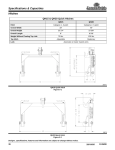
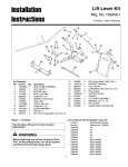
Hitch & Tube Group
Installation
Instructions
Mfg. No. 1694545
For Legacy XL / 2027 / 2927 Series Garden Tractors
Kit Contents:
6
7
Ref
1
2
3
Part No.
1679896
1679895
1930531
Qty.
1
1
4
4
5
1910531
1928919
8
4
6
7
1675766
1700773
1
1
8
1960268
4
9
10
11
12
13
14
1724807
1725599
1919438
1725600
1960033
1960462
1
1
6
2
6
4
15
16
17
18
19
1724826
1723163
1916966
1916951
1725049
4
4
4
4
4
11
9
10
5
3
4
2
11
1
68
19
12
13
18
17
15
18
16
6
17
Description
CLAMP, Hose 6", Band Type
HOSE, Vac Col, 6 x 12
SCREW, Truss Head Phillips,
#10-32 x 1/2
WASHER, #10-32
NUT, Hex Washer Assembly,
#10-32
DECAL, Cleaning Instructions
TUBE & DECAL ASSEMBLY
(Includes Ref. No. 6)
CARRIAGE BOLT,
3/8-16 x 1-1/4
HITCH, Cross Bar
HITCH, Inner
NUT, Hex, Nylock, 3/8-16
SIDE PLATE
PIN, Hair
CAPSCREW, Hex,
1/2-13 x 2-1/2
INNER SUPPORT
SPACER
WASHER, Lock, 1/2
NUT, Hex, 1/2-13
PIN, Clevis
15
14
6
Figure 1. Contents
B
WARNING
A
C
Before beginning any service work turn off the
PTO, set the parking brake, turn off the ignition,
and disconnect the spark plug wire(s).
A
D
HITCH INSTALLATION
D
1. Connnect the inner hitch (B, Figure 2) to the cross
bar hitch (C) using 3/8-16 x 1-1/4 carriage bolts (D)
and 3/8-16 locknuts (A).
E
2. Connnect the cross bar hitch (C, Figure 2) to the
side plates (E) using 3/8-16 x 1-1/4 carriage bolts (D)
and 3/8-16 locknuts (A).
Figure 2. Hitch Installation
A. Locknut,3/8-16
B. Inner Hitch
C. Cross Bar Hitch
D. Carriage Bolt, 3/8-16 x 1-1/4
E. Side Plate
1
Installation Instructions
Hitch & Tube Group
Standard Units
1. Slide capscrews (C, Figure 3) through one inner support (D), spacers (E), a second inner support (D) and
tractor frame (I). Secure with lockwashers (F) and
nuts (G).
H
A
2. Install hitches and plate (A, Figure 3) by sliding clevis
pins (H) through tractor frame (I) as shown, one inner
support (D), hitch & plate (A) and second inner support (D). Secure with hair pin (B).
F
B
D
E
I
Units with ROPS
D
G
1. Slide capscrews (C, Figure 4) through the inner support (D), spacers (E) and ROPS side place (I).
Secure with lockwashers (F) and nuts (G).
C
Figure 3. Hitch Standard Installation
A. Hitch & Plate
E. Spacers
B. Pins, Hair
F. Lockwashers, 1/2
C. Capscrews,
G. Nut, 1/2-13
1/2-13 x 2-1/2
H. Pin, Clevis
D. Inner Supports
I. Tractor Frame
2. Install hitches and plate (A, Figure 4) by sliding clevis
pins (H) through ROPS side plate (I), hitch & plate (A)
and inner support (D). Secure with hair pin (B).
Units with 3-Point Hitch
H
1. Install hitches and plate (A, Figure 5) by sliding clevis
pins (D) through 3 Point Hitch (C), and hitch & plate
(A). Secure with hair pins (B).
A
B
E
F
G
I
D
C
Figure 4. Hitch w/ROPS Installation
A. Hitch & Plate
E. Spacers
B. Pins, Hair
F. Lockwashers, 1/2
C. Capscrews, Hex,
G. Nut, 1/2-13
1/2-13 x 2-1/2
H. Pin, Clevis
D. Inner Supports
I. ROPS Side Plate
A
D
B
C
2
B
Figure 5. Hitch w/3 Point Hitch Installation
A. Hitch & Plate
C. 3 Point Hitch
B. Pins, Hair
D. Clevis Pins
Installation Instructions
Hitch & Tube Group
DISCHARGE TUBE ASSEMBLY
1. Connect the flexible hose (F, Figure 6) and clear
plastic discharge tube (B). The two should overlap
by approximately 2”.
A
B
C
2. Secure the tubes using truss head screws (E), washers (D), and locknuts (C). Insert the screws from the
inside out and poke them through the flexible hose.
D
E
3. Insert the upper end of the clear tube into the cart
sleeve. Slide the flex hose (F) over the turbo (H) and
secure with the large hose clamp (G). The hose
should overlap the turbo discharge by 2”-3”.
F
G
The clamp screw should be positioned to the inside
as shown to prevent accidental impact and removal
of the clamp.
Check that the upper end of the clear tube (B, Figure
6) is not contacting the top of the collector cover. If
necessary, cut off the clear tube flush with the sleeve
(See Wide Body Cart Operators Manual).
F
G
H
Figure 6. Discharge Tube Installation
A. Decal
E. Truss Head Screw
B. Discharge Tube
F. Hose
C. Locknut, Hose
G. Clamp
D. Washer
H. Turbo Discharge
3
Installation Instructions
Hitch & Tube Group
NOTES
MANUFACTURING, INC.
Form No. 1726330-00
Rev. 12/2003
© 2003 Simplicity Manufacturing, Inc. All Rights Reserved
TP 200-4005-00-AT-SMAN
500 N Spring Street / PO Box 997
Port Washington, WI 53074-0997 USA
4