1
6.3.96
gsm-m1-e.fm
GSM M1 Module, English: A24859-N4000-A100-1-7677
GSM
Module M1
Data
Fax
SMS
User Guide
V.24
26.2.96
gsm-m1-e.ivz
GSM M1 Module, English: A24859-N4000-A100-1-7677
Contents
GSM Module M1
Product description . . . . . . . . . . . . . . . . . . . . . . . . . . . . . . . . . . . . . . . . . . . . . . . .
Features . . . . . . . . . . . . . . . . . . . . . . . . . . . . . . . . . . . . . . . . . . . . . . . . . . . . . . . . . .
Notes on safety . . . . . . . . . . . . . . . . . . . . . . . . . . . . . . . . . . . . . . . . . . . . . . . . . . . .
Description of the interfaces . . . . . . . . . . . . . . . . . . . . . . . . . . . . . . . . . . . . . . . . .
SIM card . . . . . . . . . . . . . . . . . . . . . . . . . . . . . . . . . . . . . . . . . . . . . . . . . . . . . . .
V.24 interface . . . . . . . . . . . . . . . . . . . . . . . . . . . . . . . . . . . . . . . . . . . . . . . . . . .
Hybrid connector (manufacturer-specific) . . . . . . . . . . . . . . . . . . . . . . . . . . . . . .
Function LED . . . . . . . . . . . . . . . . . . . . . . . . . . . . . . . . . . . . . . . . . . . . . . . . . . . .
5
5
5
6
6
6
6
6
Installation / startup
Mounting the module . . . . . . . . . . . . . . . . . . . . . . . . . . . . . . . . . . . . . . . . . . . . . . . 7
Power supply / power consumption . . . . . . . . . . . . . . . . . . . . . . . . . . . . . . . . . . . 7
Cable assignment . . . . . . . . . . . . . . . . . . . . . . . . . . . . . . . . . . . . . . . . . . . . . . . . 7
Switching the GSM module on/off . . . . . . . . . . . . . . . . . . . . . . . . . . . . . . . . . . . 7
Voltage range . . . . . . . . . . . . . . . . . . . . . . . . . . . . . . . . . . . . . . . . . . . . . . . . . . . 7
Overvoltage / undervoltage . . . . . . . . . . . . . . . . . . . . . . . . . . . . . . . . . . . . . . . . . 8
Protection / on-board network connection . . . . . . . . . . . . . . . . . . . . . . . . . . . . . 8
Power consumption . . . . . . . . . . . . . . . . . . . . . . . . . . . . . . . . . . . . . . . . . . . . . . 8
Setting / testing the COM interface . . . . . . . . . . . . . . . . . . . . . . . . . . . . . . . . . . . . 8
Setting the GSM radio transfer rate . . . . . . . . . . . . . . . . . . . . . . . . . . . . . . . . . . . 9
Registering in the GSM network / PIN entry . . . . . . . . . . . . . . . . . . . . . . . . . . . . 10
Setting up and clearing down connections . . . . . . . . . . . . . . . . . . . . . . . . . . . . 10
Troubleshooting . . . . . . . . . . . . . . . . . . . . . . . . . . . . . . . . . . . . . . . . . . . . . . . . . . 11
GSM module can still be accessed . . . . . . . . . . . . . . . . . . . . . . . . . . . . . . . . . . 11
Connection cannot be set up . . . . . . . . . . . . . . . . . . . . . . . . . . . . . . . . . . . . . . 12
Own errors . . . . . . . . . . . . . . . . . . . . . . . . . . . . . . . . . . . . . . . . . . . . . . . . . . 12
System errors . . . . . . . . . . . . . . . . . . . . . . . . . . . . . . . . . . . . . . . . . . . . . . . . 12
Incorrect characters on screen . . . . . . . . . . . . . . . . . . . . . . . . . . . . . . . . . . . 13
GSM module does not dial . . . . . . . . . . . . . . . . . . . . . . . . . . . . . . . . . . . . . . 13
Cannot receive fax . . . . . . . . . . . . . . . . . . . . . . . . . . . . . . . . . . . . . . . . . . . . 13
Overview of AT commands
General AT commands . . . . . . . . . . . . . . . . . . . . . . . . . . . . . . . . . . . . . . . . . . . . . 14
GSM AT commands (GSM 07.07) . . . . . . . . . . . . . . . . . . . . . . . . . . . . . . . . . . . . 15
SMS AT commands (GSM 07.05) . . . . . . . . . . . . . . . . . . . . . . . . . . . . . . . . . . . . 15
1
26.2.96
gsm-m1-e.ivz
GSM M1 Module, English: A24859-N4000-A100-1-7677
Contents
Technical reference section
The AT standard . . . . . . . . . . . . . . . . . . . . . . . . . . . . . . . . . . . . . . . . . . . . . . . . . .
AT command line prefix . . . . . . . . . . . . . . . . . . . . . . . . . . . . . . . . . . . . . . . . . .
Connecting to your GSM module . . . . . . . . . . . . . . . . . . . . . . . . . . . . . . . . . . .
Command syntax of the AT standard . . . . . . . . . . . . . . . . . . . . . . . . . . . . . . . .
Loading the factory configuration and displaying a configuration . . . . . . . . . . .
ATVn - Result codes . . . . . . . . . . . . . . . . . . . . . . . . . . . . . . . . . . . . . . . . . . . . .
A/ - Repeat previous command line . . . . . . . . . . . . . . . . . . . . . . . . . . . . . . . . .
Setting up and clearing down connections . . . . . . . . . . . . . . . . . . . . . . . . . . . .
Operating modes . . . . . . . . . . . . . . . . . . . . . . . . . . . . . . . . . . . . . . . . . . . . . . .
Command mode. . . . . . . . . . . . . . . . . . . . . . . . . . . . . . . . . . . . . . . . . . . . . .
Transparent mode . . . . . . . . . . . . . . . . . . . . . . . . . . . . . . . . . . . . . . . . . . . .
Escape command . . . . . . . . . . . . . . . . . . . . . . . . . . . . . . . . . . . . . . . . . . . . . . .
ATH - Go on-hook . . . . . . . . . . . . . . . . . . . . . . . . . . . . . . . . . . . . . . . . . . . . . . .
ATOn - Return to transparent mode . . . . . . . . . . . . . . . . . . . . . . . . . . . . . . . . .
Setting the transfer rate . . . . . . . . . . . . . . . . . . . . . . . . . . . . . . . . . . . . . . . . . .
ATBn - Select GSM module’s operating mode . . . . . . . . . . . . . . . . . . . . . . . . .
ATD - Dial a telephone number . . . . . . . . . . . . . . . . . . . . . . . . . . . . . . . . . . . . .
Valid dial strings . . . . . . . . . . . . . . . . . . . . . . . . . . . . . . . . . . . . . . . . . . . . . . . .
ATDL - Redial last telephone number used . . . . . . . . . . . . . . . . . . . . . . . . . . . .
AT%Dn - Automatic dialing with DTR . . . . . . . . . . . . . . . . . . . . . . . . . . . . . . . . .
ATA - Answer a call . . . . . . . . . . . . . . . . . . . . . . . . . . . . . . . . . . . . . . . . . . . . . .
ATS0=n - Auto-answer mode . . . . . . . . . . . . . . . . . . . . . . . . . . . . . . . . . . . . . .
Displaying and storing a configuration . . . . . . . . . . . . . . . . . . . . . . . . . . . . . . . .
AT&F - Load factory profile . . . . . . . . . . . . . . . . . . . . . . . . . . . . . . . . . . . . . . . .
AT&V - Display configuration . . . . . . . . . . . . . . . . . . . . . . . . . . . . . . . . . . . . . . .
Configuring the module using AT commands . . . . . . . . . . . . . . . . . . . . . . . . . .
Screen outputs . . . . . . . . . . . . . . . . . . . . . . . . . . . . . . . . . . . . . . . . . . . . . . . . .
Limits of screen outputs. . . . . . . . . . . . . . . . . . . . . . . . . . . . . . . . . . . . . . . .
ATEn - Command echo. . . . . . . . . . . . . . . . . . . . . . . . . . . . . . . . . . . . . . . . .
ATQn - Activate and deactivate result codes . . . . . . . . . . . . . . . . . . . . . . . .
ATXn - Extended connect message . . . . . . . . . . . . . . . . . . . . . . . . . . . . . . .
Control line options . . . . . . . . . . . . . . . . . . . . . . . . . . . . . . . . . . . . . . . . . . . . . .
AT&Cn - Data Carrier Detect (DCD) options . . . . . . . . . . . . . . . . . . . . . . . . .
AT&Dn - Data Terminal Ready (DTR) options . . . . . . . . . . . . . . . . . . . . . . . .
Data flow control . . . . . . . . . . . . . . . . . . . . . . . . . . . . . . . . . . . . . . . . . . . . . . . .
Memory commands . . . . . . . . . . . . . . . . . . . . . . . . . . . . . . . . . . . . . . . . . . . . . . .
AT&Zn=x - Store telephone number . . . . . . . . . . . . . . . . . . . . . . . . . . . . . . . . .
ATDS=n - Dial stored telephone number . . . . . . . . . . . . . . . . . . . . . . . . . . . . .
AT&Wn - Store configuration . . . . . . . . . . . . . . . . . . . . . . . . . . . . . . . . . . . . . .
AT&Yn - Configuration at power-up . . . . . . . . . . . . . . . . . . . . . . . . . . . . . . . . . .
ATZn - Load user profile . . . . . . . . . . . . . . . . . . . . . . . . . . . . . . . . . . . . . . . . . .
2
16
16
16
16
17
17
18
19
19
19
19
19
20
20
20
21
22
22
22
23
23
24
24
25
25
26
26
26
26
26
27
27
27
28
28
28
29
29
29
30
30
26.2.96
gsm-m1-e.ivz
GSM M1 Module, English: A24859-N4000-A100-1-7677
Contents
AT+C commands for GSM . . . . . . . . . . . . . . . . . . . . . . . . . . . . . . . . . . . . . . . . . .
AT+CGMI - Request manufacturer ID . . . . . . . . . . . . . . . . . . . . . . . . . . . . . . . .
AT+CGMM - Request model ID . . . . . . . . . . . . . . . . . . . . . . . . . . . . . . . . . . . .
AT+CGMR - Request revision ID . . . . . . . . . . . . . . . . . . . . . . . . . . . . . . . . . . .
AT+CGSN - Request product serial number ID . . . . . . . . . . . . . . . . . . . . . . . . .
AT+CHUP - Hangup call . . . . . . . . . . . . . . . . . . . . . . . . . . . . . . . . . . . . . . . . . .
AT+CEER - Extended error report . . . . . . . . . . . . . . . . . . . . . . . . . . . . . . . . . . .
AT+CMEE - Report mobile equipment error . . . . . . . . . . . . . . . . . . . . . . . . . . .
AT+CREG - Network registration . . . . . . . . . . . . . . . . . . . . . . . . . . . . . . . . . . .
AT+COPS - Operator selection . . . . . . . . . . . . . . . . . . . . . . . . . . . . . . . . . . . . .
AT+COPS? - Display current network operator . . . . . . . . . . . . . . . . . . . . . .
AT+COPS=? - Display list of available network operators . . . . . . . . . . . . . .
AT+COPS= .., .. - Use this network operator . . . . . . . . . . . . . . . . . . . . . . . .
AT+CPIN - Enter PIN and query blocks . . . . . . . . . . . . . . . . . . . . . . . . . . . . . . .
AT+CPIN2 - Enter PIN2 and query PIN2 blocks . . . . . . . . . . . . . . . . . . . . . . . .
AT+CPWD - Change password . . . . . . . . . . . . . . . . . . . . . . . . . . . . . . . . . . . . .
AT+CSQ - Signal quality . . . . . . . . . . . . . . . . . . . . . . . . . . . . . . . . . . . . . . . . . .
AT+CKPD - Keypad control . . . . . . . . . . . . . . . . . . . . . . . . . . . . . . . . . . . . . . . .
AT+CXXSN - Single-numbering parameterization . . . . . . . . . . . . . . . . . . . . . . .
AT+CXXMOC - Parameterize for outgoing calls . . . . . . . . . . . . . . . . . . . . . . . .
AT+CPBS - Select phonebook memory storage . . . . . . . . . . . . . . . . . . . . . . . .
AT+CPBR - Read phonebook entries . . . . . . . . . . . . . . . . . . . . . . . . . . . . . . . .
AT+CPBW - Write phonebook entry . . . . . . . . . . . . . . . . . . . . . . . . . . . . . . . . .
AT+CBST - Select bearer service type . . . . . . . . . . . . . . . . . . . . . . . . . . . . . . .
AT+CRC - Cellular result code . . . . . . . . . . . . . . . . . . . . . . . . . . . . . . . . . . . . . .
AT+CLIP - Calling line identification presentation . . . . . . . . . . . . . . . . . . . . . . .
AT+CPAS - Phone activity status . . . . . . . . . . . . . . . . . . . . . . . . . . . . . . . . . . .
AT+FCLASS - Select mode . . . . . . . . . . . . . . . . . . . . . . . . . . . . . . . . . . . . . . . .
AT+CXXCID - Card identification . . . . . . . . . . . . . . . . . . . . . . . . . . . . . . . . . . . .
AT+C commands for the short message service (SMS) . . . . . . . . . . . . . . . . . .
AT+CSMS - Select message service . . . . . . . . . . . . . . . . . . . . . . . . . . . . . . . .
AT+CPMS - Preferred message storage . . . . . . . . . . . . . . . . . . . . . . . . . . . . . .
AT+CMGF - Message format . . . . . . . . . . . . . . . . . . . . . . . . . . . . . . . . . . . . . .
AT+CSCA - Service center address . . . . . . . . . . . . . . . . . . . . . . . . . . . . . . . . . .
AT+CMGR - Read message . . . . . . . . . . . . . . . . . . . . . . . . . . . . . . . . . . . . . . .
AT+CMGS - Send message . . . . . . . . . . . . . . . . . . . . . . . . . . . . . . . . . . . . . . .
AT+CMGW - Write message to memory . . . . . . . . . . . . . . . . . . . . . . . . . . . . .
AT+CMGD - Delete message . . . . . . . . . . . . . . . . . . . . . . . . . . . . . . . . . . . . . .
AT+CNMI - New message indications . . . . . . . . . . . . . . . . . . . . . . . . . . . . . . .
AT+CMGL - List messages . . . . . . . . . . . . . . . . . . . . . . . . . . . . . . . . . . . . . . . .
AT+CMS ERROR - message service failure result codes . . . . . . . . . . . . . . . . .
Fax operation conforming to TR-29.2 . . . . . . . . . . . . . . . . . . . . . . . . . . . . . . . . .
30
31
31
31
32
32
32
33
35
36
36
37
38
39
40
41
42
43
44
46
47
48
49
50
51
52
53
54
55
55
56
56
57
57
58
58
59
59
59
60
60
61
3
26.2.96
gsm-m1-e.ivz
GSM M1 Module, English: A24859-N4000-A100-1-7677
Contents
The S-registers . . . . . . . . . . . . . . . . . . . . . . . . . . . . . . . . . . . . . . . . . . . . . . . . . . .
ATSn? - Read an S-register . . . . . . . . . . . . . . . . . . . . . . . . . . . . . . . . . . . . . . . .
ATSn=x - Write to an S-register . . . . . . . . . . . . . . . . . . . . . . . . . . . . . . . . . . . .
Binary and decimal values in S-registers . . . . . . . . . . . . . . . . . . . . . . . . . . . . . .
Bit position registers . . . . . . . . . . . . . . . . . . . . . . . . . . . . . . . . . . . . . . . . . . . . .
Overview of the S-registers . . . . . . . . . . . . . . . . . . . . . . . . . . . . . . . . . . . . . . .
AT&Tn - Test functions . . . . . . . . . . . . . . . . . . . . . . . . . . . . . . . . . . . . . . . . . . .
AT&T0 - Terminate an active test . . . . . . . . . . . . . . . . . . . . . . . . . . . . . . . . .
AT&T1 - Initiate local digital test loop . . . . . . . . . . . . . . . . . . . . . . . . . . . . . .
ATIn - Display GSM module I-data . . . . . . . . . . . . . . . . . . . . . . . . . . . . . . . . . .
61
62
62
63
64
65
68
68
68
69
Technical data
General . . . . . . . . . . . . . . . . . . . . . . . . . . . . . . . . . . . . . . . . . . . . . . . . . . . . . . . . . .
V.24 interface . . . . . . . . . . . . . . . . . . . . . . . . . . . . . . . . . . . . . . . . . . . . . . . . . . . . .
Hybrid connector (manufacturer-specific) . . . . . . . . . . . . . . . . . . . . . . . . . . . . .
GSM modes . . . . . . . . . . . . . . . . . . . . . . . . . . . . . . . . . . . . . . . . . . . . . . . . . . . . . .
Fax . . . . . . . . . . . . . . . . . . . . . . . . . . . . . . . . . . . . . . . . . . . . . . . . . . . . . . . . . . .
Data . . . . . . . . . . . . . . . . . . . . . . . . . . . . . . . . . . . . . . . . . . . . . . . . . . . . . . . . . .
SMS . . . . . . . . . . . . . . . . . . . . . . . . . . . . . . . . . . . . . . . . . . . . . . . . . . . . . . . . .
70
70
71
72
72
72
72
GSM documentation
GSM reference documents . . . . . . . . . . . . . . . . . . . . . . . . . . . . . . . . . . . . . . . . . 73
ETSI contact . . . . . . . . . . . . . . . . . . . . . . . . . . . . . . . . . . . . . . . . . . . . . . . . . . . . . . 73
General information
CE-Sign . . . . . . . . . . . . . . . . . . . . . . . . . . . . . . . . . . . . . . . . . . . . . . . . . . . . . . . . . 74
Service . . . . . . . . . . . . . . . . . . . . . . . . . . . . . . . . . . . . . . . . . . . . . . . . . . . . . . . . . . 74
4
6.3.96
gsm-m1-e.fm
GSM M1 Module, English: A24859-N4000-A100-1-7677
GSM Module M1
Product description
The GSM module is a GSM terminal for transmitting data, faxes and SMS (short message service) text messages in GSM networks (GSM = global system for mobile communication).
The GSM Module M1 comprises the following components:
• GSM transceiver;
• Data and power supply unit;
• Serial interface (V.24) for data transmission and control;
• Manufacturer-specific interface for DC power supply, external antenna and audio
signals.
When the GSM Module M1 is registered in the network, it serves as a standard modem for fax and data transmission for a computer connected to the V.24 interface. Special AT+C commands as per GSM 07.07 or GSM 07.05 for controlling GSM-related
functions (PIN entry, network selection, etc.) and for the short message service are
available via the V.24 interface.
Features
The GSM Module M1 offers the following features:
• Transparent data transmission at 2400, 4800 and 9600 bps (BS24,25,26);
• Group 3, Class 2 fax transmission conforming to TR-29.2 at 2400, 4800, 7200
and 9600 bps;
• Short message service mobile originated (SMS MO, TS22)
• Short message service mobile terminated (SMS MT, TS21)
Notes on safety
The GSM Module M1 conforms to GSM standards. However, note that the device can
still emit radiation and therefore must not be used or even switched on in certain environments.
• Leaving the GSM Module M1 switched on in airplanes is prohibited by law.
• The module must not be used near service stations, fuel depots, chemical plants or
blasting operations.
• The module may also interfere with the functioning of electronic medical devices
(hearing aids, pacemakers, etc.) that are not properly shielded. In case of doubt, consult your physician. Do not touch the antenna during a call.
• Using the GSM Module M1 in the direct vicinity of electronic devices (radios, televisions, PCs, etc.) can cause slight interference.
5
26.2.96
GSM M1 Module, English: A24859-N4000-A100-1-7677
gsm-m1-e.fm
GSM Module M1
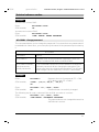
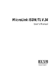
Description of the interfaces
The GSM Module M1 has interfaces for the power supply, for control and data transmission, for an external antenna and for a SIM card as well as an LED that indicates
operating statuses. These interfaces will be described below. For a detailed description
including pin assignment, see the section entitled “Technical data”
.
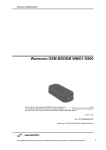
SIM card
The GSM Module M1 must have a SIM card to operate in the GSM network. To install
this card, press the yellow button to eject the carrier and insert the SIM in the carrier.
Then push the carrier into the housing, making sure that it locks into place.
V.24 interface
The serial interface is used for controlling the GSM Module M1 as well as for data, fax
and SMS transmission.
Connector:
9-pin DSUB (female) conforming to DIN 41652
Pin assignment:
See the section entitled “Technical data”
Logic:
V.24 asynchronous
Baud rates:
2400 - 19200 baud, autobauding
Parity:
None
Character format:
8 data bits
Stop bits:
1
Level:
Conforming to CCITT Recommendation V.28
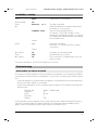
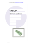
Hybrid connector (manufacturer-specific)
The hybrid connector contains the power supply, ignition (for switching the device on
and off) and the connection for the external antenna (GSM 900 MHz antenna). It is connected via the cable supplied.
Pin assignment:
Meaning of pins:
See the section entitled “Technical data”
.
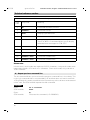
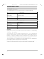
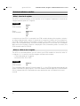
Function LED
LED off
LED flashing slowly
LED flashing rapidly
Device switched off – not ready
Device switched on – ready
Device switched on – connection setup
For a detailed function indication, use the corresponding AT commands.
6
6.3.96
gsm-m1-e.fm
GSM M1 Module, English: A24859-N4000-A100-1-7677
Installation / startup
Mounting the module
Two standard options are available for mounting the GSM Module M1 :
• Retaining clip
• Velcro
Before applying the velcro, make sure that the surface of the M1 (recess provided in
center of base) and the corresponding surface are free of dust and oil.
The mounting location must comply with the following environmental conditions:
• Temperature range -20 °C – +55 °C for full operability
• Temperature from insolation < 110 °C
• Light condensation permissible
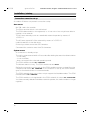
Power supply / power consumption
Cable assignment
Power is supplied via the cable included in the scope of supply. The relevant wires are
marked as follows:
Red
POWER +8 V – +24 V DC
Violet
IGNITION(ON/OFF)
Brown
GND
Ground
Switching the GSM module on/off
The GSM Module M1 switches on when a positive voltage of 5 - 24 V is applied to IGNITION if a voltage of 8 - 24 V is simultaneously applied to POWER.
The module switches off when a voltage of less than +1 V is applied to IGNITION. An
existing call is correctly disconnected. This voltage must be applied for a minimum of
550 ms.
Important:
Be sure to switch off the module using IGNITION; simply disconnecting the power supply at POWER can damage the SIM if it is being written to at the time.
Voltage range
Nominal voltage:
Extreme voltage:
13,2 V DC
8 - 32 V DC
7
26.2.96
GSM M1 Module, English: A24859-N4000-A100-1-7677
gsm-m1-e.fm
Installation / startup
Overvoltage / undervoltage
Correct operation of the M1 in send mode cannot be guaranteed if input voltages fall
below 8 V.
When input voltages exceed 32 V, the supply voltage is disconnected in order to protect the electronic components from an overvoltage.
Input voltages >100 V destroy the module.
Protection / on-board network connection
When installed, the M1 must be protected by a medium time-lag fuse with a nominal
value of 1A or a fast fuse with a nominal value of 1.6 A. For vehicle installation the M1
must be directly connected to the battery.
Important:
Do not connect the ground cable to the power supply, since this could result in a short
circuit via the antenna cable.
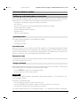
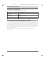
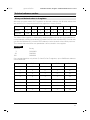
Power consumption
Supply
voltage
Channel
search
12 V
24 V
Standby
Send mode
Typical
Max.
Typical
Max.
130 mA
70 mA
150 mA
220 mA
500 mA
70 mA
45 mA
150 mA
120 mA
500 mA
Setting / testing the COM interface
In order to control the GSM Module M1 and transfer data via the serial interface (COM
port), the interface parameters must be set.
The parameters settings are as follows:
COM port:
1-4, depending on which one the M1 was connected to
Baud rate:
2400 - 19200 baud, autobauding
Data bits
8
Parity
None
corresponds to 8N1
Stop bits
1
Duplex
Full
H
For instructions on how to set these parameters, see the user guide for the computer
or terminal program used.
8
6.3.96
gsm-m1-e.fm
GSM M1 Module, English: A24859-N4000-A100-1-7677
Installation / startup
In order to test the interface and your settings, enter AT. The GSM module should then
respond with OK. If it does not do so, configure a different interface in the communication program and try again. Also check the cable. When this test has been successfully completed, check the functionality of the GSM module by entering AT&T1. This
command activates a test loop. From now on, all the characters entered from your
GSM module should be echoed on the computer. Terminate the test by entering the
escape sequence +++. If the test is acknowledged by the NO CARRIER code, the
GSM module’s data functionality is operating correctly.
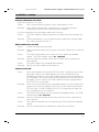
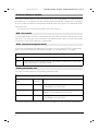
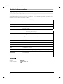
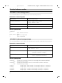
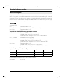
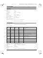
Setting the GSM radio transfer rate
The transfer rate (baud rate) via the radio interface can be set, for example, using a terminal program. The ATBn command allows you to set the transfer rate in the GSM network.
Enter the ATI8 command to display the current list.
ATBn
[n=7,11,13,25,27,29,70,99]
Option
Effect
Bit/s
Synchronism
Distant station
ATB99
9600
Asynchronous
Mode set to automode
ATB7
2400
Asynchronous
V.22bis
ATB11
4800
Asynchronous
V.32
ATB13
9600
Asynchronous
V.32
ATB25
2400
Asynchronous
V.110 ISDN
ATB27
4800
Asynchronous
V.110 ISDN
ATB29
9600
Asynchronous
V.110 ISDN
ATB70
9600
Fax
Fax Group 3
Example:
Enter:
M1
ATB13
Permanently switches mode to 9600 bit/s.
Enter:
M1
ATB7
Permanently switches mode to 2400 bit/s.
9
26.2.96
gsm-m1-e.fm
GSM M1 Module, English: A24859-N4000-A100-1-7677
Installation / startup
Registering in the GSM network / PIN entry
In order for the GSM module to access the GSM network, you may have to enter the
PIN for the SIM card. You can do this using the AT+CPIN=“
....” command. The
AT+CPIN? command allows you to inquire whether or not you must enter a password
and what type of password must be entered. The following blocks are possible:
• PIN or PUK
• Device code or PUK of the device code
• Network link: the network operator blocks the device so that, without a network
PIN, it runs only in its own network. If you wish to operate the device in another network, you must enter the PIN or PUK.
• Service operator link: similar to the network link but implemented by the service operator rather than the network operator (again, you must enter PIN or PUK).
Note:
The PIN (4-8 positions) is the PERSONAL IDENTIFICATION NUMBER and must be entered to unblock the device. You are allowed 3 attempts to enter your PIN. If you enter
the wrong PIN 3 times in a row, the PIN is blocked and must be unblocked by means
of a PUK (PIN UNBLOCKING KEY). You are allowed 10 attempts.
You can enter the PUK any number of times for the network link and service operator
link.
Example:
Enter:
GSM module
Enter:
M1
AT+CPIN?
+CPIN: SIM PIN
AT+CPIN=1234
OK
Queries the password to be entered.
PIN for the SIM card; must be entered.
PIN entry
PIN was correct; the SIM card can be
accessed.
After entering the PIN, you can enter the AT+CREG? command to determine whether
the GSM module is registered in the GSM network.
Setting up and clearing down connections
Normally, you will set up connections with the aid of your communication program.
However, you can also manually instruct your GSM module to set up and clear down a
connection. The simplest sequence would be as follows: Load your communication
program and enter the following command:
10
6.3.96
gsm-m1-e.fm
GSM M1 Module, English: A24859-N4000-A100-1-7677
Installation / startup
Enter:
GSM module
Enter:
M1
AT&F
OK
ATD<tel. no.>
CONNECT xxxx
Enter:
Pause
+++
M1 returns:
Enter:
M1 returns:
Pause
OK
ATH
OK
Loads factory configuration.
The dial command
Dials the telephone number and informs
you when it is successful.
"xxxx" is the baud rate for the
connection. The GSM module is now
operating in transparent mode, i.e. entries
you make via the keyboard are transmitted
to the distant end.
Interrupt command:
Press the “+“ key three times in rapid
succession.
Changes to command mode.
Command to go on-hook
The connection is cleared down; M1 has
gone on-hook.
For more information, see Technical reference sec7tion.
Troubleshooting
GSM module can still be accessed
As long as the GSM module is still responding to commands, you can enter the AT&F0
command to load the factory configuration. In any case, this will permit further operation.
• Check whether the communication program is configured for the serial interface to
which the GSM module is connected.
• Check the parameters of your communication program. The following settings will
always work:
Transfer rate
Data bits
Parity
Stop bits
Duplex
2400 – 19200 baud
8
None
1
Full
Check whether other programs (e.g. printer spooler) are interfering with the functioning of the communication program. Restart your computer without additional programs, with the operating system alone (switch off and then on).
11
26.2.96
gsm-m1-e.fm
GSM M1 Module, English: A24859-N4000-A100-1-7677
Installation / startup
Connection cannot be set up
A number of factors can prevent connection setup.
Own errors
• No SIM card in the module.
• The PIN or another block is not unblocked.
• The GSM data module is not registered, i.e. it has not or has not yet been able to
register in the network.
• The M1 was manually set to an unavailable network operator by means of
+COPS=1.
• The M1 was signed off of the network by means of +COPS=2.
• Invalid characters in the dial string.
• Dial string contains more than 30 characters.
• Command line contains more than 39 characters.
System errors
• A connection is already set up.
• The call is not answered within 60 seconds after dialing because the distant station:
– is not ready,
– is not a modem,
– does not support the selected operating mode.
The GSM module returns NO CARRIER.
• The distant station is busy. The GSM module returns BUSY.
• Before the connection can be set up, the GSM module receives a signal from the
computer and returns NO CARRIER. If no connection is set up, the GSM module
goes on-hook and returns to command mode.
• The GSM network does not or does not yet support the fax/data modes. The GSM
module returns NO CARRIER.
• The GSM module is not registered in the GSM network. It returns NO DIALTONE.
• You have manually dialed a forbidden network operator; the radio modem no longer
registers.
12
6.3.96
gsm-m1-e.fm
GSM M1 Module, English: A24859-N4000-A100-1-7677
Installation / startup
Incorrect characters on screen
• Duplicate characters on screen
Cause:
Your communication program is set to half-duplex or echo.
Remedy: Enter ATE0 to deactivate command echo in command mode or
deactivate the echo in the communication program.
• Only the characters from the distant station are incorrect
Cause:
The GSM module’s data format does not match that of the distant station.
Remedy: Set the parameters in your communication program accordingly (data
bits, parity, stop bits to 8, N, 1).
GSM module does not dial
Cause:
Remedy:
A cable has been disconnected.
Make sure that all cables are securely connected. Tighten all connecting
screws.
Cause:
The GSM network does not or does not yet support the fax/data
modes. The GSM module returns NO CARRIER.
Ask your network operator when these modes will be supported in
your network.
Remedy:
Cause:
Remedy:
The GSM module has activated barred dialing.
Switch the GSM module off and then on.
Cannot receive fax
Cause:
Remedy:
Cause:
Remedy:
Cause:
Remedy:
Some fax programs that support TR-29.2 Class 2 expect the bits of the
fax code to arrive in an order different from the one defined in the
SP2388 specification. If the GSM module transmits the fax data bits to
the computer in the wrong order, the fax program cannot receive whole
fax pages. For this reason, the GSM module has been equipped with
the AT+FOPT=n command.
Enter one of the following two commands and then check whether the
system is functioning correctly: AT+FOPT=1,0 (bit order as specified in
TR-29.2 Class 2, Draft SP2388); AT+FOPT=1,1 (opposite bit order, factory configuration for all countries).
The GSM network does not yet support the fax/data modes. The GSM
module returns NO CARRIER.
Ask your network operator when these services will be supported in
your network.
Your network operator has not released your SIM card for the fax/data
modes.
Ask your network/service operator to release these features.
13
6.3.96
gsm-m1-e.fm
GSM M1 Module, English: A24859-N4000-A100-1-7677
Overview of AT commands
General AT commands
A/
+++
ATA
ATDx
ATDIx
ATDL
ATDS=n
ATE0
ATE1
ATH
ATIn
ATI0
ATI1
ATI2
ATI8
ATI9
ATO0
ATQ0
ATQ1
ATSn=x
ATSn?
ATS0=n
ATS0=0
ATV0
ATV1
ATX0
ATX1
ATX2
ATX3
ATX4
ATZn
AT&C0
AT&C1
AT&D0
AT&D1
AT&D2
AT&D3
AT&F
AT&T0
AT&T1
AT&V
AT&Wn
AT&Yn
14
Repeat previous command line
Switch to command mode when connected
Answer call
Dial the dial string "x"
Dial ISDN number "x"
Redial last telephone number used
Dial stored telephone number
Disable command echo
Enable command echo
Disconnect existing connection
Display product data
Display product code for GSM module
Display software checksum
Determine firmware ROM checksum
Display supported modes
Display device ID
Switch from command mode to transparent mode
Display result codes
Do not output result codes to computer
Assign value "x" to S-register "n"
Read value of S-register "n"
Go off-hook after n-th ringing signal (n = "1" - "5")
No automatic answering of calls
Display result codes as digits
Display result codes as text
Display connection without baud rate. Ignore busy signal.
Display connection with baud rate. Ignore busy signal.
Same as ATX1
Same as ATX1 but report BUSY
Same as ATX3
Load user profile "n"
DCD always ON
DCD line ON only in the presence of carrier signal (connection)
Ignore DTR status
At DTR -> OFF: Command mode without going on-hook
At DTR -> OFF: Go on-hook, command mode, auto-answer off
At DTR -> OFF: Go on-hook, factory configuration same as AT&F
Load factory configuration
Terminate an active test
Initiate local digital test loop
Display current configuration
Store current configuration as user profile "n"
Load user profile "n" at power-up
6.3.96
gsm-m1-e.fm
GSM M1 Module, English: A24859-N4000-A100-1-7677
Overview of AT commands
AT&Zn=x
AT%Dn
AT+
Store telephone number "x" in memory "n"
Automatic dialing with DTR
Fax commands
GSM AT commands (GSM 07.07)
AT+CGMI
AT+CGMM
AT+CGMR
AT+CGSN
AT+CHUP
AT+CEER
AT+CMEE
AT+CREG
AT+COPS
AT+CPIN
AT+CPIN2
AT+CPWD
AT+CSQ
AT+CKPD
AT+CXXSN
AT+CXXMOC
AT+CPBS
AT+CPBR
AT+CPBW
AT+CBST
AT+CRC
AT+CLIP
AT+CPAS
AT+FCLASS
AT+CXXCID
Display manufacturer ID
Display model ID
Display version of GSM module
Display serial number (IMEI)
Terminate all calls
Display reason last call was disconnected
Extended error messages to GSM 07.07
Display registration status
Commands relating to network operator selection
Enter PIN and query blocks
Enter PIN2 and query PIN2 blocks
Change PIN
Display signal quality information
Key simulation
Single-numbering parameterization
Parameterize for outgoing calls
Select phonebook
Read phonebook entry
Write phonebook entry
Select bearer service type
Cellular result code
Calling line identification presentation
Phone activity status
Select mode
Card identification
SMS AT commands (GSM 07.05)
AT+CSMS
Select message service
AT+CPMS
Preferred message storage
AT+CMGF
Message format
AT+CSCA
Service center address
AT+CMGR
Read message
AT+CMGS
Send message
AT+CMGW
Write message to memory
AT+CMGD
Delete message
AT+CNMI
New message indications
AT+CMGL
List messages
Please note: The GSM module also recognizes some AT-standard commands that it
does not execute, but it ignores these commands and returns either OK or ERROR.
15
6.3.96
gsm-m1-e.fm
GSM M1 Module, English: A24859-N4000-A100-1-7677
Technical reference section
The AT standard
With the development of intelligent modems, an command language was introduced
in the U.S. called the AT standard. Over the past few years, this language has been consistently enhanced and has gained international acceptance. Most modems and communication programs work with this command language or can be set to use it.
AT command line prefix
The AT standard is a line-oriented command language. Each command line must begin
with the letters AT, with the sole exception of the A/ command. The commands are introduced at the end of this section. The letters AT are also known as the attention code.
The attention code signals your GSM module that one or more commands will follow.
The GSM module examines this command line prefix.
Connecting to your GSM module
You have connected your GSM module to your PC. You can now connect to your GSM
module. To do so, start up a communication program on your PC.
Set the following transmission parameters (characteristics):
COM interface:
1 - 4, depending on which one the M1 is connected to
Rate:
2400 - 19200 baud
Data bits:
8
Parity:
None
Stop bits:
1
Duplex:
Full
The GSM module supports autobauding on the V.24 interface with transfer rates from
2400 to 19200 baud and the data format 8N1.
Command syntax of the AT standard
• Command lines must always begin with AT.
• Multiple commands can be combined on one command line. To improve legibility,
you can enter spaces between the individual commands. The GSM module ignores
these spaces.
• Commands that are specified in this manual with "0" in the last position can also be
entered without this "0". Example: ATQ has the same effect as ATQ0.
• A command line must end with a <CR> character, which is entered by pressing "Enter" on the keyboard. This fact will not be mentioned again in this manual.
16
6.3.96
gsm-m1-e.fm
GSM M1 Module, English: A24859-N4000-A100-1-7677
Technical reference section
• The <CR> character can be followed by a <LF> character but this character will be
ignored by the GSM module.
Sample command lines:
ATH
ATS7?Q0E1
ATD0123456789
• When making corrections, use the Backspace key or Ctrl-H to delete the character
to the left of the cursor.
• The command line is not executed until the <CR> character is received.
Loading the factory configuration and displaying a configuration
The AT&F and AT&V commands allow you to load and display the factory configuration.
Enter:
M1 returns:
AT&F0
OK
Enter:
M1:
AT&V
Loads the factory configuration and transfers it to the PC.
The settings are displayed on the screen.
ATVn - Result codes
The GSM module acknowledges all commands.
Example:
Enter:
M1 returns:
AT&F0
OK
The ATVn command allows you to determine whether result codes will appear as alphanumeric text or a numerical code:
ATVn
[n=0,1]
Option
Result
ATV0
Selects the short result code format (digits). Useful if the GSM module is
to be controlled from the computer using a communication program.
ATV1
Selects the long result code format. Factory configuration.
17
26.2.96
GSM M1 Module, English: A24859-N4000-A100-1-7677
gsm-m1-e.fm
Technical reference section
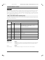
Overview of the short and long result code formats
Short
code
Long code
Meaning
0
OK
Command executed, no error
1
CONNECT
Connection set up
2
RING
Ringing signal detected
3
NO CARRIER
Connection not set up or disconnected
4
ERROR
Incorrect command or command too long.
The AT+CMEE= 2 command allows you to display
extended error messages to GSM 07.07.
6
NO DIALTONE
Connection cannot be set up.
7
BUSY
Distant station busy
10
CONNECT 2400
Connection at 2400 bit/s
30
CONNECT 4800
Connection at 4800 bit/s
32
CONNECT 9600
Connection at 9600 bit/s
Please note:
In both cases, result codes are made up of ASCII characters. Long result codes must
begin and end with <CR> and <LF> characters. Short result codes only end with a
<CR> character.
A/ - Repeat previous command line
The A/ command allows you to reissue the previous command line in its entirety. This
is the only command that is not preceded by AT and that does not have to end with
<CR> (Enter). A/ is mainly used when the line was busy or the call was not answered.
In this case, the GSM module repeats the dial command.
Example:
Enter:
GSM module:
AT D 01999341
BUSY
Enter:
GSM module:
A/
Reissues the command (= D 01999341).
18
6.3.96
gsm-m1-e.fm
GSM M1 Module, English: A24859-N4000-A100-1-7677
Technical reference section
Setting up and clearing down connections
Once you have read through this section, you will be able to use your GSM module together with your communication program to perform the following functions:
• Interrupt a connection using the escape command.
• Go off-hook.
• Set up a connection by manually dialing the telephone number.
• Store a telephone number.
• Dial a stored telephone number.
• Answer a call.
• Switch to auto-answer.
Operating modes
The GSM module operates in two different modes:
• Command mode
• Transparent mode
Command mode
When you switch on your system, the GSM module is in command mode and is ready
to receive and execute your commands. All characters that the GSM module receives
via the COM interface in this mode are interpreted as commands and, if a phone connection is present, are not transferred to the distant station.
Transparent mode
In transparent mode, the GSM module transfers every character sent and received via
the COM interface just as it is.
Escape command
Before attempting to dial your first call, you must know how to interrupt or disconnect
a call at any time. This involves the following two steps:
• Enter to switch to command mode.
• Disconnect the call by entering ATH.
Example:
Situation: The GSM module is operating in transparent mode, i.e. a connection is set
up to a distant station.
Change to command mode:
• Do not press any key for at least one second.
• Press the key three times in rapid succession (within one second).
• Do not press another key for at least one second.
The GSM module switches to command mode, i.e. it interrupts the flow of data and
19
26.2.96
gsm-m1-e.fm
GSM M1 Module, English: A24859-N4000-A100-1-7677
Technical reference section
returns the result code OK. The connection is not yet cleared down. The pause before
and after the "+" characters ensures that the GSM module will interpret this command
as the escape command in transparent mode and will then switch to command mode.
Going on-hook
• Disconnect the call by entering ATH (see next section).
ATH - Go on-hook
In command mode, the ATH command causes the GSM module to disconnect an existing call. The call is also disconnected if the distant station goes on-hook or the radio
connection in the GSM network is interrupted.
ATOn - Return to transparent mode
If you wish to interrupt the data flow only briefly, you can use the ATOn command to
return your GSM module to transparent mode, i.e. the data flows once again.
ATOn
[n=0]
Option
Result
ATO0
Switches the GSM module back to transparent mode when it was previously switched to command mode.
Setting the transfer rate
The GSM module supports the following transfer rates:
Transfer rates
Rate
Bit/s
Bearer
service
Corresponding modem types
2400
24
Analog modems conforming to V.22bis,
ISDN adapter to V.110 ISDN
4800
25
Analog modemso conforming to V.32 with
fallback, ISDN adapter to V.110 ISDN
9600
26
Analog modems conforming to V.32,
ISDN adapter to V.110 ISDN
To change and permanently set the rate for the radio link, use the ATBn command.
20
6.3.96
gsm-m1-e.fm
GSM M1 Module, English: A24859-N4000-A100-1-7677
Technical reference section
Example:
Your PC is set to 19200 baud, i.e. higher than the maximum GSM transfer rate of 9600
bit/s. This means that the GSM module receives more data from the PC than it can
transfer to the GSM network. In order to prevent a data overflow, the module must be
able to interrupt the data flow from the PC. This is accomplished by means of the RTS/
CTS hardware data flow control.
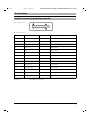
ATBn - Select GSM module’s operating mode
The ATBn command also allows you to set the GSM module’s operating mode permanently for all connections.
ATBn
[n=7,11,13,25,27,29,70,99]
Result
Option
Bit/s
Synchronism
ATB99
Distant station
Automatically sets the mode to match
the baud rate set for the PC.
Factory configuration
ATB 7
2400
Asynchronous
V.22bis
ATB11
4800
Asynchronous
V.32
ATB13
9600
Asynchronous
V.32
ATB25
2400
Asynchronous
V.110 ISDN
ATB27
4800
Asynchronous
V.110 ISDN
ATB29
9600
Asynchronous
V.110 ISDN
ATB70
9600
Asynchronous
Fax Group 3
Example:
Enter:
GSM module:
ATB13
Permanently switches the mode to 9600 bit/s with the result that
all radio connections are permanently set to a transfer rate of
9600 bit/s.
Enter:
GSM module
ATB99
Automatically changes to the rate of the COM interface.
21
26.2.96
gsm-m1-e.fm
GSM M1 Module, English: A24859-N4000-A100-1-7677
Technical reference section
ATD - Dial a telephone number
In order to dial a telephone number, enter the ATD command followed by the number.
Example:
Enter:
GSM module
and returns:
ATD 0199341
Dials the telephone number 0199341.
CONNECT 2400
As soon as the module detects the carrier for the distant station, it returns the CONNECT result code. Data transfer can now begin.
Valid dial strings
• A dial string comprises digits from "0" to "9" (the telephone number), letters "A" to
"C" and the special dialing characters "i","+" and ";".
i
This character must be located between the ATD command and the
telephone number (ATDix) and causes the GSM module to switch to
ISDN mode for this call.
+
This character must be located at the beginning of a dial string and
serves to access the international exchange of a GSM network.
Example:
You are in Sweden and wish to set up a connection to Munich.
Dial: ATD+4989<telephone number>
• A dial string must contain no more than 30 characters. A longer string will not be
dialed.
• A command line including the dial string must not exceed 39 characters. Although
longer command lines are displayed, they are rejected in their entirety.
Example:
ATD0045890235168338
This dial string comprises 16 characters. The command line on the screen contains
19 characters.
22
6.3.96
gsm-m1-e.fm
GSM M1 Module, English: A24859-N4000-A100-1-7677
Technical reference section
ATDL - Redial last telephone number used
This command allows you to redial the last telephone number that you dialed, regardless of whether the last dialing attempt was successful.
Example:
Enter:
GSM module:
ATD123456789
BUSY
Enter:
GSM module:
ATDL
Redials 123456789.
GSM module dials 123456789
The number is busy.
AT%Dn - Automatic dialing with DTR
The AT%Dn command allows you to activate and deactivate automatic dialing of the
telephone number stored in telephone number memory "0". The number is dialed if the
computer sets the DTR control line connected to the COM interface to ON.
AT%Dn
[n=0..1]
Option
Result
AT%D0
Deactivates automatic DTR dialing.
AT%D1
Activates automatic DTR dialing if DTR switches from OFF to ON;
dials the telephone number "x" that was stored in telephone number
memory "0" by means of the AT&Z0=x command.
Example:
Enter:
AT&Z0=123456789 Stores the telephone no. "123456789"
in telephone number memory "0".
GSM Data_Module: OK
Enter:
AT%D1
Telephone number has been stored.
Activates DTR dialing.
GSM module:
Command has been executed.
OK
DTR is OFF
DTR switches ON
DTR switches OFF
"123456789" is dialed automatically.
GSM module goes on-hook.
23
26.2.96
gsm-m1-e.fm
GSM M1 Module, English: A24859-N4000-A100-1-7677
Technical reference section
ATA - Answer a call
The GSM module does not automatically answer calls after you switch on your computer. In accordance with the factory configuration, it does not go off-hook. The ATA
command causes your GSM module to go off-hook when the phone rings. You determine whether or not you wish to answer.
ATS0=n - Auto-answer mode
The ATS0=n command allows you to configure your GSM module so that it will automatically answer calls. "n" represents the number of ringing signals before the call is
answered. Permissible values are from "0" to "5".
ATS0=n
Option
Result
ATS0=0
No auto-answer: incoming calls are ignored.
ATS0=1
The GSM module goes off-hook after the first ringing signal.
...
etc.
ATS0=5
The GSM module goes off-hook after the fifth ringing signal.
[n=0..5]
You can use the ATA command to answer calls at any time, regardless of these settings.
Displaying and storing a configuration
The GSM module works with a set of parameters that determine its functioning. This
set of parameters is called the active configuration profile. Values for these parameters
are predefined in a factory configuration that you can use at any time when you load it
using the AT&F command. The GSM Module M1 allows you to modify the active configuration profile by means of AT or S-register commands. These options will be described in subsequent sections. When you switch off the GSM module, any changes
you made to the active configuration profile are lost. When you switch it on again, the
active configuration profile once again corresponds to the factory configuration. However, the GSM module has two nonvolatile memory blocks in which you can store configuration profiles (AT&Wn command, page 29). These blocks are user profiles "0" and
"1". When you switch on your system, the GSM module loads the user profile that you
set by means of the AT&Yn command. For more information, see the section entitled
“AT&Yn - Configuration at power-up”
.
Please note:
When the module is supplied, both user memories contain the factory profile.
24
6.3.96
gsm-m1-e.fm
GSM M1 Module, English: A24859-N4000-A100-1-7677
Technical reference section
AT&F - Load factory profile
This command allows you to load the factory profile that was supplied with the GSM
module.
AT&F
Option
Result
AT&F
If your GSM module stops functioning due to a faulty configuration,
this command resets the module to the factory configuration.
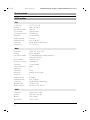
AT&V - Display configuration
The AT&V0 command allows you to display the active configuration profile on the screen.
Enter:
AT&V
The GSM module then transfers the information to the computer, which displays it on
the screen.
Example:
You have a GSM module and have loaded the factory configuration by means of the
AT&F command. Now enter the AT&V command. The following is displayed on the
screen:
AT&V
ACTIVE PROFILE:
B99 E1 L2 M1 Q0 V1 X4 Y0 %D0 &C1 &D2 &G0 &Y0
S00:000 S01:000 S02:043 S03:013 S04:010 S05:008 S06:002 S07:060 S08:002
S09:006 S10:007 S12:050 S14:6AH S16:00H S18:000 S21:30H S22:46H S23:1CH
S25:005 S26:001 S27:00H
0
STORED PROFILE 0:
B99 E1 L2 M1 Q0 V1 X4 Y0 &C1 &D2 &G0
S00:000 S14:6AH S18:000 S21:30H S22:46H S23:1CH S25:005 S26:001 S27:00H
x S27:00H
STORED PROFILE 1:
B99 E1 L2 M1 Q0 V1 X4 Y0 &C1 &D2 &G0
S00:000 S14:6AH S18:000 S21:30H S22:46H S23:1CH S25:005 S26:001 S27:00H
x S27:00H
TELEPHONE NUMBERS:
&Z0=
&Z1=
&Z2=
&Z3=
OK
25
26.2.96
gsm-m1-e.fm
GSM M1 Module, English: A24859-N4000-A100-1-7677
Technical reference section
Configuring the module using AT commands
This section describes the standard AT commands that allow you to configure your
GSM module. These commands are grouped according to subject area.
Screen outputs
Limits of screen outputs
When you receive data that is reproduced on the screen (data echo), the text is usually
shifted upward when the edge of the screen is reached. When you generate screen
outputs using AT commands (e.g. AT&V), a maximum of 30 lines is displayed for each
command. If, for example, you enter the AT&V command several times on the same
line (AT&V&V&V), a maximum of 30 lines is displayed.
ATEn - Command echo
The ATEn command affects the echo of characters that the GSM module receives from
your computer when the GSM module is in command mode.
ATEn
[n=0,1]
Option
Result
ATE0
Command echo off: Select the ATE0 setting when the computer itself is
echoing keyboard entries on the screen and no command echo is expected from the GSM module. Please note: If you enter the ATE0 command
and your computer is expecting character echo, the computer will no longer display the entered characters on the screen. You are then working
blind.
ATE1
Command echo on: Select the ATE1 setting when your computer is configured to expect the characters received by your GSM module to be returned. Factory configuration.
ATQn - Activate and deactivate result codes
The ATQn command allows you to control the transmission of result codes as acknowledgments to AT commands (e.g. OK, ERROR, RING).
ATQn
Option
Result
ATQ0
Outputs result codes.
ATQ1
Suppresses result codes. Important for unattended operation.
26
[n=0,1]
6.3.96
gsm-m1-e.fm
GSM M1 Module, English: A24859-N4000-A100-1-7677
Technical reference section
ATXn - Extended connect message
ATXn
[n=0..4]
Option
Result
ATX0
The GSM module returns only the CONNECT code as soon as a satisfactory connection has been set up. A busy signal is ignored.
ATX1
The GSM module transmits an extended connect message with transfer
rate information (CONNECT xxxx) as soon as a satisfactory connection has
been set up. For more information on extended result codes, see the ATV1
command. A busy signal is ignored.
ATX2
Same as ATX1.
ATX3
As in the case of ATX1, the GSM module transmits an extended connect
message. A busy signal is detected and, if applicable, the BUSY code is
returned.
ATX4
As in the case of ATX1, the GSM module transmits an extended connect
message. A busy signal is detected and, if applicable, the BUSY code is
returned.
Control line options
AT&Cn - Data Carrier Detect (DCD) options
This command affects the DCD line connected to the computer’s serial interface.
AT&Cn
[n=0,1]
Option
Result
AT&C0
The GSM module sets the DCD control line connected to the computer’s
serial interface to ON regardless of the data carrier status of the distant
station.
AT&C1
DCD specifies the data carrier status of the distant station. DCD ON
indicates that a connection exists.
27
26.2.96
gsm-m1-e.fm
GSM M1 Module, English: A24859-N4000-A100-1-7677
Technical reference section
AT&Dn - Data Terminal Ready (DTR) options
AT&Dn
[n=0..3]
Option
Result
AT&D0
The GSM module ignores the status of the DTR control line connected
to the COM interface.
AT&D1
When the DTR line switches from ON to OFF, the GSM module changes
to command mode. The existing connection to the distant station is not
cleared down.
AT&D2
When the DTR line switches from ON to OFF, the GSM module sets up
a connection to the distant station, switches to command mode and
deactivates auto-answer mode. Auto-answer can be reactivated by
resetting DTR to ON.
AT&D3
The transition of DTR to OFF has the same effect as an AT&F command,
i.e. the factory configuration is loaded. An existing connection to the distant station is cleared down.
Data flow control
Even if your PC is set, for example, to 19200 baud, the maximum GSM rate that can
be used is 9600 bit/s. A higher setting causes the GSM module to receive more data
from the PC than it can transfer to the GSM network. In order to prevent a data overflow, it must be able to interrupt the data flow from the PC. This is accomplished by
means of the RTS/CTS hardware data flow control, which switches over the COM interface so as to interrupt the RTS (computer) and CTS (GSM module) control lines.
Memory commands
The GSM module is equipped with a 128-byte nonvolatile RAM in which the values of
the modifiable S-registers and other values are stored. This section describes the values, how to store them and how to use them.
28
6.3.96
gsm-m1-e.fm
GSM M1 Module, English: A24859-N4000-A100-1-7677
Technical reference section
AT&Zn=x - Store telephone number
The user memory can hold 4 telephone numbers. The AT&Zn= command allows you
to store a dial string in telephone number memory "n" (n represents a value from "0" to
"3").
Example:
Enter:
GSM module:
AT&Z0 = 01999341
OK
The AT&Zn= command saves only digits and special characters ("i", "+"). It ignores punctuation, spaces and all meaningless characters. The dial string must contain no more
than 20 characters. If you enter a longer dial string, it is not stored and the ERROR code
is displayed on the screen. The AT&Zn= command itself is not stored with the dial
string.
ATDS=n - Dial stored telephone number
The ATDS=n command allows you to dial the "n"-th stored telephone number (n represents a value from "0" to "3"). This command dials the dial string as though it were a
telephone number entered directly via the keyboard.
Example:
Enter:
GSM module:
ATDS=0
01999341 and initiates the dialing procedure.
AT&Wn - Store configuration
When you modify the active configuration profile using AT or S-register commands,
these modifications exist only in the RAM and are deleted when you switch off your
GSM module. When switched on again, the GSM module loads the configuration from
a nonvolatile memory. The AT&Wn command allows you to store your modifications in
this nonvolatile memory. Two separate memory areas are available for this purpose.
AT&Wn
Option
Result
AT&W0
Stores the active configuration profile in user memory "0".
AT&W1
Stores the active configuration profile in user memory "1".
[n=0,1]
Consequently, you always have two different user profiles in your GSM module ready
to be called up.
29
26.2.96
gsm-m1-e.fm
GSM M1 Module, English: A24859-N4000-A100-1-7677
Technical reference section
AT&Yn - Configuration at power-up
The AT&Yn command allows you to determine which user profile ("0" or "1") will be loaded at power-up.
AT&Yn
Option
Result
AT&Y0
The profile in user memory "0" will be loaded at power-up.
Factory configuration
AT&Y1
The profile in user memory "1" will be loaded at power-up.
[n=0,1]
Please note:
When the module is supplied, both user memories contain the factory configuration.
ATZn - Load user profile
Regardless of how your active configuration profile is currently set up, the ATZn command allows you to reload your own user profile at any time. Any existing connection
is cleared down.
ATZn
Option
Result
ATZ0
Load user profile "0".
ATZ1
Load user profile "1".
[n=0,1]
AT+C commands for GSM
Special AT commands are used for controlling GSM-related functions of the GSM
Module M1 such as PIN entry, network selection and IMEI output and for controlling the
short message service. These commands start with AT+C and are specified in the Technical Specifications (TS) GSM 07.07 for the general part and GSM 07.05 for SMS from the
ETSI (European Telecommunications Standards Institute). Standardization is not yet complete. Some of the commands implemented in the GSM Module M1 may still be
changed within the framework of the standardization process. For the purpose of future
compatibility, these commands are always prefixed by +CXX.
Example:
Enter:
GSM module
AT+CXXSN = ?
+CXXSN: 1=voice/FAX
The implementation of the AT+C commands for GSM-related functions of the GSM
Module M1 is based on TS GSM 07.07 Version 0.1.0.
30
6.3.96
gsm-m1-e.fm
GSM M1 Module, English: A24859-N4000-A100-1-7677
Technical reference section
AT+CGMI - Request manufacturer ID
This command provides you with the name of the module manufacturer.
AT+CGMI
Option
Result
AT+CGMI
Displays manufacturer.
Example:
Enter:
GSM module:
AT+CGMI
+CGMI: SIEMENS
OK
AT+CGMM - Request model ID
This command provides you with the name of the module.
AT+CGMM
Option
Result
AT+CGMM
Displays module name.
Example:
Enter:
Response:
AT+CGMM
+CGMM: M1
OK
AT+CGMR - Request revision ID
This command provides you with the version of the GSM module and the software creation date.
AT+CGMR
Option
Result
AT+CGMR
Displays the version number and creation date.
Example:
Enter:
GSM module:
AT+CGMR
+CGMR: Ver.02.001 10.08.95
OK
31
26.2.96
gsm-m1-e.fm
GSM M1 Module, English: A24859-N4000-A100-1-7677
Technical reference section
AT+CGSN - Request product serial number ID
This command provides you with the serial number of the GSM module. The serial
number has the GSM format.
AT+CGSN
Option
Result
AT+CGSN
Displays the serial number. In GSM, each mobile telephone is
assigned a unique number, known as the IMEI (International Mobile
Equipment Identity).
Example:
Enter:
GSM module:
AT+CGSN
IMEI: 445199518750
OK
AT+CHUP - Hangup call
This command allows you to terminate all calls.
AT+CHUP
Option
Result
AT+CHUP
Terminate all calls.
Example:
Enter:
GSM module:
AT+CHUP
OK
AT+CEER - Extended error report
This command allows you to query the reason why the last call was disconnected. The
information returned can be useful if there were problems with connection setup or if
a connection was interrupted.
AT+CEER
Option
Result
AT+CEER
Displays reason last call was disconnected.
32
6.3.96
GSM M1 Module, English: A24859-N4000-A100-1-7677
gsm-m1-e.fm
Technical reference section
Example:
Enter:
GSM module:
AT+CEER
+CEER: 10,08
OK
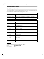
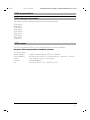
AT+CMEE - Report mobile equipment error
If an error occurs while you are processing a command by means of AT+C, the problem
may be located in the data or GSM section of the M1. For example, if a data connection
is set up, the phonebook cannot be accessed at the same time. Or is the problem in
the SIM card? Is it inserted or has the PIN been omitted? Extended error messages
help you isolate errors more easily. However, you must first enable these messages
from the PC using this command.
AT+CMEE
Option
Result
AT+CMEE=<mode n>
Resets the mode.
AT+CMEE?
Displays the way in which error messages are reported
to the PC.
AT+CMEE=?
Displays the modes supported by the M1 in the form of
a complete list of the values that can be assumed by
<mode n>.
<mode n>
n= [0..2]
0
The error messages are not interpreted but, generally, only an ERROR
code is returned.
1
When an error occurs, an extended message to the PC is generated that
specifies the cause of error as a number.
2
Same as “1“ except that the error is output as text.
33
26.2.96
gsm-m1-e.fm
GSM M1 Module, English: A24859-N4000-A100-1-7677
Technical reference section
Possible error messages in response to an AT+C command
0
Phone failure
1
No connection to phone (transceiver part of M1)
2
Transceiver-adaptor link reserved
3
Operation not allowed
4
Operation not supported
5
PH-SIM PIN required
10
SIM not inserted
11
SIM PIN required
12
SIM PUK required
13
SIM failure
14
SIM busy
15
SIM wrong
16
Incorrect password
20
Memory full
21
Invalid index
22
Not found
23
Memory failure
24
Text string too long(+CPBW)
25
Invalid characters in text string
26
Dial string too long
27
Invalid characters in dial string
30
No network service
31
Network timeout
100
Unknown
Example:
Enter:
GSM module:
34
AT+CREG?
+CME ERROR: 10
6.3.96
GSM M1 Module, English: A24859-N4000-A100-1-7677
gsm-m1-e.fm
Technical reference section
AT+CREG - Network registration
Data transmission is possible only if the GSM module is registered in the network. This
command provides you with information on the module’s registration status in the network.
AT+CREG
Option
Result
AT+CREG?
Displays mode n and the
registration status < CREG STATUS n>.
AT+CREG=?
Displays a list of the modes supported.
AT+CREG=<mode n>
Selects a new mode.
AT+CREG?
Command
AT+CREG?
Result code
+CREG: <mode n>, <CREG status>
<mode n>
0
n= [0]
Changes in registration status are not forwarded to the PC.
<CREG status>
status= [0..3]
STATUS n
Meaning
Explanation
0
Not registered;
ME is not searching for a new operator.
No network operator found; the GSM module
cannot register, nor is it searching for a new
operator.
1
Registered
The GSM module has successfully registered in
the network and all services are available.
2
Not registered,
but ME is
searching for a
new operator.
The M1 is not registered but is searching for a
new network operator.
See AT+COPS, commands relating to network
operator selection.
3
Registration
denied.
The selected network cannot be accessed at
this time.
4
Unknown
The current status in relation to the network
cannot be determined at this time.
35
26.2.96
GSM M1 Module, English: A24859-N4000-A100-1-7677
gsm-m1-e.fm
Technical reference section
Example:
Enter:
GSM module:
AT+CREG?
+CREG: 0,0 => not registered
OK
AT+COPS - Operator selection
These commands allow you to read out the current network operator, display a list of
available network operators or select a operator directly. Various command extensions
are available.
AT+COPS
Command
Result
AT+COPS?
Displays current network operator.
AT+COPS=?
Displays a list of network operators that are currently
available via radio.
AT+COPS=<mode n>,
<format f>,
<network operator>
Allows you to instruct the GSM module to use a specific network operator.
AT+COPS? - Display current network operator
This command displays the network operator that is currently selected. It also provides
you with information on whether the radio modem has selected this network operator
automatically or whether you manually instructed it to select this operator.
A result code with the following format is returned in response to the AT+COPS? command:
AT+COPS?
Command
AT+COPS?
Result code
+COPS: <mode n>, <format f>, <operator>
36
6.3.96
gsm-m1-e.fm
GSM M1 Module, English: A24859-N4000-A100-1-7677
Technical reference section
< mode n>
n= [0...3]
Mode n
Meaning
Explanation
0
Automatic
Network operator is selected automatically.
1
Manual
Network operator is selected manually.
2
Sign off of network
The GSM-M1 is signed off of the network.
3
Sets format f only.
You can select the format for displaying the
network operator. This is true only of the read
command AT+COPS?.
<format f>
n= [0..2]
0
Long, alphanumeric
format
The operator is displayed in 16-character alphanumeric format.
2
Numeric format
The operator is displayed in numeric format.
Operator
Network operator
The network operator is displayed in
format f.
Example:
Enter:
GSM module:
AT+COPS?
+COPS: 0, 0, " Operator Name "
OK
AT+COPS=? - Display list of available network operators
This command instructs the module to display a list of available network operators. The
list must first be generated. That process can take up to 60 seconds.
AT+COPS=?
Command
AT+COPS=?
Result code
+COPS: List with (<STATUS n>,
<operator, alphanumeric format>, <operator, numeric format>)
37
26.2.96
GSM M1 Module, English: A24859-N4000-A100-1-7677
gsm-m1-e.fm
Technical reference section
Evaluate the result code using the following table:
<+COPS status n>
n= [0..3]
STATUS n
Meaning
Explanation
0
Unknown
Status unknown
1
Available
Network operator is available.
2
Current
This network operator is the one currently in use.
3
Forbidden
This network operator is forbidden.
Operator
Network
operator
Displays the network operator in text format and
numeric format.
Example:
Enter:
GSM module:
AT+COPS=?
+COPS: (2, “
+COPS: (3, “
OK
D1 TELEKOM
D2 PRIVAT
“, “26201“),
“, “26202“)
AT+COPS= .., .. - Use this network operator
This command allows you to select a network operator manually or to activate the automatic selection of a network operator. It is recommended that you first display a list of
available network operators.
AT+COPS= <mode n>, <format f>, <operator>
Mode n
Mode n specifies how the new network operator is to be selected.
The meaning is the same as for the AT+COPS? read command.
Format f
<format f> specifies the format to be used for displaying the operator.
The GSM M1 supports only the numeric format for selection.
Operator
The network operator to be used (numeric format).
Example:
Enter:
M1:
AT+COPS=0
OK
Enter:
GSM module:
AT+COPS=1, 2, “26201“
OK
38
The M1 automatically searches for a operator.
6.3.96
gsm-m1-e.fm
GSM M1 Module, English: A24859-N4000-A100-1-7677
Technical reference section
Please note:
The GSM module must not register when you select a forbidden operator manually!
Otherwise, you will not be able to set up any more connections. Display the list to find
out which operators are forbidden and which are allowed. Use the AT+CREG command
to find out whether or not the GSM module is registered. You will also be unable to set
up any connections if you have set mode n to “2” (sign off of network).
AT+CPIN - Enter PIN and query blocks
The PIN (personal identification number) is provided to prevent unauthorized use of the
GSM module. The PIN is usually a 4-position secret code. If this block is activated, you
must enter your PIN before you can use the module’s full range of functions. When you
query the status, the system displays result codes relating to the chip card and tells you
either that you must enter a PIN or that the chip card has already been read, in which
case PIN entry is unnecessary.
AT+CPIN
Command
Result
AT+CPIN?
Queries the PIN that must be entered.
AT+CPIN=<PIN>[,
<new PIN>]
PIN entry. The PIN can comprise up to 8 positions.
If a PUK must be entered, the PIN is entered at the same
time. It will then be stored as a new PIN.
AT+CPIN?
Result code
Meaning
+CPIN: READY
M1 expects no further password. All blocks are released
and services are available without restriction.
+CPIN: SIM PIN
M1 expects the PIN for the SIM card.
+CPIN: SIM PUK
M1 expects the PUK for the SIM card, including a PIN.
+CPIN: PH-SIM PIN
M1 expects a device code.
+CPIN: PH-SIM
PUK
M1 expects the device PUK, including a PIN that is stored
as a device code.
39
26.2.96
gsm-m1-e.fm
GSM M1 Module, English: A24859-N4000-A100-1-7677
Technical reference section
Example:
You enter the correct PIN:
Enter:
GSM module:
AT+CPIN=“1234“
OK
You enter an incorrect PIN:
Enter:
GSM module:
AT+CPIN=“1234“
+CME: ERROR: WRONG PASSWORD
AT+CPIN2 - Enter PIN2 and query PIN2 blocks
Phase 2 includes SIM cards with an FDN phonebook. You can activate a block on the
card in order to restrict the telephone numbers that can be called to those contained
in this directory. To modify these entries, you must enter PIN2 with the aid of the
AT+CPIN2 command. All entries are similar to those for the AT+CPIN command. This
command is accepted only if the card also supports this functionality.
Please note: PIN2 protects the FDN phonebook. In order to modify the FDN phonebook
by means of the AT+CPBW=... command, you must first enter PIN2. If you have not yet
done so, an error message is returned. After entering PIN2, you can read or write any
number of directory entries without having to enter PIN2 each time. As soon as you use
a command that is not related to the phonebook, PIN2 is “forgotten”
. It is also forgotten
if you do not access the phonebook for a period of 5 minutes.
AT+CPIN2
Command
Result
AT+CPIN2?
Queries whether PIN2 has already been entered, must still
be entered or is blocked.
AT+CPIN2=<PIN>[,
<new PIN>]
PIN2 entry. PIN2 can comprise up to 8 positions.
If PUK2 must be entered, PIN2 is entered at the same time.
It is then stored as a new PIN2.
AT+CPIN2?
Result code
Meaning
+CPIN: READY
M1 does not expect PIN2; it has already been entered.
+CPIN: SIM PIN2
M1 expects PIN2 for the SIM card.
+CPIN: SIM PUK2
M1 expects PUK2 for the SIM card, including PIN2.
40
6.3.96
gsm-m1-e.fm
GSM M1 Module, English: A24859-N4000-A100-1-7677
Technical reference section
Example:
You enter the correct PIN2:
Enter:
GSM module:
AT+CPIN2=“1234“
OK
You enter an incorrect PIN2:
Enter:
GSM module:
AT+CPIN2=“1234“
+CME: ERROR: WRONG PASSWORD
AT+CPWD - Change password
This command allows you to change the password. Since more than one password will
be available for future uses, you must specify the name of the password upon entering
it.
AT+CPWD
Command
Result
AT+CPWD=?
Displays a list of the passwords supported. These currently include the PIN, device code and PIN2.
AT+CPWD=<name>,
<old password>,
<new password>
This command instructs the GSM module to change the
relevant password. When changing the password, you
must enter both the old and new password. This ensures
that changes can be made only if access is authorized.
Example:
Enter:
GSM module:
Enter:
GSM module:
Requests the list of passwords (SC = SIM,
PS = device code, P2 = PIN2)
+CPWD: (“SC,8“,“PS,8“, “P2,8“)
OK
AT+CPWD=?
AT+CPWD= “sc“,“1234“,“4321“
OK
Password was successfully changed.
The following result code is returned if the old PIN you enter is incorrect:
Enter:
GSM module:
AT+CPWD= “sc“,“0123“,“4321“
+CME ERROR: INCORRECT PASSWORD
The password was not changed because the
old PIN was incorrect.
41
26.2.96
GSM M1 Module, English: A24859-N4000-A100-1-7677
gsm-m1-e.fm
Technical reference section
AT+CSQ - Signal quality
The quality of the radio connection between the GSM module and the base station
varies depending on environmental conditions. This command provides you with information on the current reception quality.
AT+CSQ
Command
Result
AT+CSQ
Displays current receive values.
AT+CSQ=?
Displays a list of values representing receive levels and
receive errors.
AT+CSQ, AT+CSQ=?
Command
AT+CSQ
Result code
+CSQ: <receive level>, <receive errors>
<receive level>
0
-113 dBm or less
1
-111 dBm
2...30
-109... -53 dBm
31
-51 dBm or greater
99
Unknown or cannot be detected
<receive
errors>
(As a percentage): See GSM 05.08, section 8.2.4, Range
of Parameter.
99
Unknown or cannot be detected
Example:
Enter:
GSM module:
42
AT+CSQ
+CSQ: 10, 1
OK
6.3.96
gsm-m1-e.fm
GSM M1 Module, English: A24859-N4000-A100-1-7677
Technical reference section
AT+CKPD - Keypad control
This command allows you to simulate keystrokes on the GSM mobile telephone. Input
corresponds to the actuation of keys on the Siemens S3COM.
AT+CKPD
Command
Result
AT+CKPD=<key>
Instructs the GSM module to simulate the key <key>.
AT+CKPD=?
Displays a list of keys that are supported.
AT+CKPD=?
Command
AT+CKPD=?
Result code
+CKPD: “0123456789*#CDEISUXYZ[]“
<key>
Meaning of the keys
0-9, *,#
Key 0 - 9, “*“
, “#“
“C“ or “c“
Clears the display.
“E“ or “e“
Simulates the End key.
“I“ or “i“
Simulates the Info key.
“S“ or “s“
Simulates the Start key.
“X“ or “x“
Phonebook key
“Y“ or “y“
Deletes the last character.
“Z“ or “z“
Exits menu.
[
Simulates the left softkey.
]
Simulates the right softkey.
Example:
You would like to enter the key combination “*#06#“:
Enter:
GSM module:
AT+CKPD=*#06#
OK
43
26.2.96
GSM M1 Module, English: A24859-N4000-A100-1-7677
gsm-m1-e.fm
Technical reference section
AT+CXXSN - Single-numbering parameterization
Some GSM network operators support single-numbering and some support multinumbering. You can determine which form of numbering is supported by your operator from
whether your chip card has one number or more than one number at which it can be
called for multiple voice or data services.
Example:
• You apply for the 9600 bit/s data and fax transmission services from your network
operator and receive 2 telephone numbers with your chip card, one for when you
wish to be called via the 9600 bit/s data service and one so that you can be reached
via the fax service. This means that your network operator supports multinumbering.
• You have received only one telephone number for the 9600 bit/s data and fax services. This means that your network operator supports single-numbering. (Singlenumbering is not supported in Germany.)
When another party wishes to reach you, your telephone must decide which service
will answer the call before it rings. If you set your GSM module to fax, all incoming
calls will be answered by the FAX service.
AT+CXXSN
Command
Result
AT+CXXSN
Displays the value currently set for +CXXSN.
AT+CXXSN=<SN mode>
Sets the single-numbering receive mode to the relevant mode.
AT+CXXSN=?
Displays a list of values for single-numbering receive
modes.
44
6.3.96
gsm-m1-e.fm
GSM M1 Module, English: A24859-N4000-A100-1-7677
Technical reference section
AT+CXXSN=?
Command
AT+CXXSN=?
Result code
+CXXSN: <0,1,2>
<SN mode>
Meaning of the mode
0
The next incoming call will be answered by the voice service
(TS11).
1
The next incoming call will be answered by the voice/fax service.
This is required if your network operator supports only TS61 and
not TS62.
2
The next call will be answered by the fax or data service, depending on the active application on your PC. If a fax application is
active, the module answers the call as a fax call.
Example:
You wish to set the SN mode to fax/data:
Enter:
GSM module:
AT+CXXSN=2
OK
45
26.2.96
GSM M1 Module, English: A24859-N4000-A100-1-7677
gsm-m1-e.fm
Technical reference section
AT+CXXMOC - Parameterize for outgoing calls
The following services are available for fax transmission in GSM:
• Teleservice 61 (TS61)
Combined voice and fax
This service exists as an imitation of combination fax machines and allows you to
change from a voice connection to fax transmission.
• Teleservice 62 (TS62)
Automatic fax
This service is purely for faxing.
If your network operator supports only one of these services, you can use this command to configure your GSM module accordingly. You must do this in networks that
support only TS61 if you are to be able to send or receive faxes at all.
AT+CXXMOC
Command
Result
AT+ CXXMOC
Displays value currently set for + CXXMOC.
AT+ CXXMOC <MOC mode>
Sets the single-numbering receive mode to the
relevant mode.
AT+ CXXMOC =?
Displays a list of values for MOC modes.
AT+ CXXMOC =?
Command
AT+CXXMOC=?
Result code
+CXXMOC: <0,1>
<MOC mode>
Meaning of the mode
0
Fax calls to the radio network are set up using
TS62.
1
All outgoing fax calls are set up using TS61 fax/
voice, but calls are terminated when the fax
transmission is terminated.
Example:
You wish to set the MOC mode to TS61:
Enter:
GSM module:
46
AT+CXXMOC=1
OK
6.3.96
gsm-m1-e.fm
GSM M1 Module, English: A24859-N4000-A100-1-7677
Technical reference section
AT+CPBS - Select phonebook memory storage
When reading or writing a phonebook entry, you must tell the M1 which phonebook
memory will be affected by the subsequent read/write jobs. The following phonebook
memories are supported in the M1:
• Phonebook on the SIM card
• Last number redial memory
• Own telephone numbers
• FDN phonebook (if this is also supported by the SIM card)
AT+CPBS
Command
Result
AT+ CPBS= dir.
Selects a new phonebook.
AT+ CPBS?
Provides you with information on which phonebook is currently activated.
AT+ CPBS=?
Displays a list of all the telephone directories supported.
AT+CPBS=?
Command
AT+CPBS=?
Result code
+CPBS: “MD“ , “SM“ , “OW“ , “FD“
Meaning
MD
Last number redial memory; displays the last telephone numbers that you dialed.
SM
SIM card; this is the standard phonebook containing the
entries.
OW
Own telephone number; this phonebook contains your own
telephone numbers under which you can be reached. Normally, you only need to read this directory since you cannot
call your own number and it does not change.
FD
Fixed dialing number; this is a second phonebook. If the relevant block is set, only the numbers from this FDN phonebook
can be called. This phonebook and the block are protected by
PIN2.
47
26.2.96
GSM M1 Module, English: A24859-N4000-A100-1-7677
gsm-m1-e.fm
Technical reference section
AT+CPBR - Read phonebook entries
This command allows you to read the phonebook that was selected by means of the
AT+CPBS command. You must also enter the number of the relevant position or a
range of numbers.
AT+CPBR
Command
Result
AT+CPBR=index1[,index2]
Reads the phonebook entry with the number index1.
If you also enter a second index, reads the phonebook from index1 to index2.
AT+CPBR=?
Provides you with information on the maximum
number of entries that can be contained in the directory and the maximum size of these entries.
The test command provides you with information on the format of the phonebook that
was selected by means of AT+CPBS.
AT+CPBR=?
Command
AT+CPBR=?
Result code
+CPBR: <index>, <number length>, <text
length>
Meaning
Index
Maximum number of entries in the phonebook
Number length
Length of a telephone number
Text length
Length of a telephone number name
48
6.3.96
gsm-m1-e.fm
GSM M1 Module, English: A24859-N4000-A100-1-7677
Technical reference section
AT+CPBW - Write phonebook entry
This command allows you to write an entry to the phonebook. You have the option of
entering the telephone number with or without a name.
AT+CPBW= [index][,number, [type], [text]]
Meaning
Index
Stores the entry with the position number “index” in the phonebook.
If you omit the index, an available position is sought; otherwise, the
entry is written to the specified position, regardless of whether this
position is already being used. If you specify only an index without a
number or text, this means that you wish to delete the relevant entry.
Number
Number to be written to the phonebook
Type
International
145
Other
129
Type of number; can be omitted.
If no type is specified, the type is automatically generated from the
telephone number.
A “+“ character at the beginning of the telephone number means that
its type is international.
Text
Name to be stored with this number
49
26.2.96
GSM M1 Module, English: A24859-N4000-A100-1-7677
gsm-m1-e.fm
Technical reference section
AT+CBST - Select bearer service type
This command selects the bearer service with data rate and the connection element
to be used when data calls are originated.
AT+CBST
Command
Result
AT+CBST=[<speed>
[,<name>[,<ce>]]]
Selects new speed, name and ce
AT+CBST?
Displays speed, name and ce
AT+CBST=?
Displays list of supported speed, list of supported
name and list of supported ce (Connection Elements)
<speed n>
0
autobauding
4
2400 bps (V.22bis)
6
4800 bps (V.32)
7
9600 bps (V.32)
68
2400 bps (V.110)
70
4800 bps (V.110)
71
9600 bps (V.110)
<name n>
0
50
n=[0]
asynchronous modem
<ce n>
0
n=[0,4,6,7,68,70,71]
transparent
n=[0]
6.3.96
GSM M1 Module, English: A24859-N4000-A100-1-7677
gsm-m1-e.fm
Technical reference section
AT+CRC - Cellular result code
This command controls whether or not the extended format of incoming call indication
is used. When enabled, an incoming call is indicated with unsolicited result code +
CRING: <type> instead of the normal RING.
AT+CRC
Command
Result
AT+CRC?
Displays mode n
AT+CRC=?
Displays a list of supported modes
AT+CRC=<mode n>
Selects a new mode
AT+CRC?
Command
AT+CRC?
Rsult Code
+CRC: <mode n>
<mode n>
1
enables extendet format
0
disables extendet format
n=[0,1]
+CRING: <type>
<type>
Meaning
ASYNC
asynchronous transparent
FAX
facsimile
51
26.2.96
GSM M1 Module, English: A24859-N4000-A100-1-7677
gsm-m1-e.fm
Technical reference section
AT+CLIP - Calling line identification presentation
This command refers to the GSM supplementary service CLIP (Calling Line Identification Presentation) that enables a called subscriber to get the calling line identity (CLI)
when receiving a call.
The set command + CMP=<n> enables or disables the presentation of the CLI at the
M1. It has no effect on the execution of the service CLIP in the network. When enabled
+CLIP: <number>,<type> response is returned after every RING result code.
The read command +CLIP? gives the status of mode n and also triggers an interrogation of the provision status of CLIP in the network.
AT+CLIP
Command
Result
AT+CLIP?
Displays mode n, mode m
AT+CLIP=?
Displays a list of supported modes n
AT+CLIP=<mode n>
Selects new mode
AT+CLIP?
Command
AT+CLIP?
Result Code
+CLIP: <mode n>,<mode m>
<mode n>
1
enables extendet format
0
disables extendet format
<mode m>
52
0
CLIP not provisioned
1
CLIP provisioned
2
unknown
n=[0,1]
m=[0,1,2]
6.3.96
GSM M1 Module, English: A24859-N4000-A100-1-7677
gsm-m1-e.fm
Technical reference section
AT+CPAS - Phone activity status
This command returns the activity status of the GSM module M1. It can be used to interrogate the M1 before requesting action.
AT+CPAS
Command
Result
AT+CPAS
Displays status
AT+CPAS=?
Displays a list of supported stati
AT+CPAS=?
Command
AT+CPAS=?
Result Code
+CPAS: 0 1 2 3 4 5
0
ready
1
unavailable
2
unknown
3
ringing
4
call in progress
5
asleep
53
26.2.96
GSM M1 Module, English: A24859-N4000-A100-1-7677
gsm-m1-e.fm
Technical reference section
AT+FCLASS - Select mode
This command puts the M1 into a particular mode of operation (data, fax).
AT+FCLASS
Command
Result
AT+FCLASS?
Displays mode n
AT+FCLASS=?
Displays a list of supported modes
AT+FCLASS=<mode n>
Selects new mode
AT+FCLASS?
Command
AT+FCLASS=?
Result Code
0, 2
0
data
2
fax
Important
Example: The customer has a D2 card and uses M1 with the following default settings:
+FCLASS=0, B99, +CRC=0
When he receives a call (MTC), "RING" is displayed on his PC. The call can now be accepted by means of "ATA". The DSA in the M1 accepts the call as a data call proper irrespective of whether it is a data or fax call. The reason for this is that B99 causes the
incoming service identifier to be ignored. With fax calls, this causes problems of many
kinds because the user does not know which service is being used.
The command "AT+CRC=1" allows the M1 to also indicate the service identifier for incoming calls so that the user what service is being used.
To ensure that all units involved in the call accept the call in the proper manner, the user
should select the correct service using AT+FCLASS before accepting the call.
.
54
6.3.96
GSM M1 Module, English: A24859-N4000-A100-1-7677
gsm-m1-e.fm
Technical reference section
AT+CXXCID - Card identification
Execution of this command displays the SIM number.
AT+CXXCID
Command
Result
AT+CXXCID
Displays SIM number
AT+CXXCID=?
OK
AT+C commands for the short message service (SMS)
The module supports several of the AT+C commands specified in TS GSM 07.05 for
using the short message service with the M1. In order to provide an application on the
connected computer with complete information on the short messages, the M1 supports PDU mode. A PDU (protocol data unit) contains almost all the information relating
to a short message that is transferred in the GSM network. For a more detailed description of the various PDUs, see TS GSM 03.40, which describes the implementation of
the short message service.
The implementation of AT+C commands for SMS is based on TS GSM 07.05
Version 4.4.0.
55
26.2.96
gsm-m1-e.fm
GSM M1 Module, English: A24859-N4000-A100-1-7677
Technical reference section
AT+CSMS - Select message service
This command allows you to select the short message service.
Parameter command syntax
Command
Possible response(s)
+CSMS=<service>
+CSMS: <mt>,<mo>, <bm>
+CSMS ERROR : <err>
+CSMS?
+CSMS: <service>,<mt>,<mo>, <bm>
+CSMS=?
+CSMS: (list of supported <service>s)
Values implemented
<service>:
0
GSM 03.40 and 03.41
<mt>,<mo>, <bm>
0
Type not supported
1
Type supported
AT+CPMS - Preferred message storage
This command allows you to select the memory to be used for read and write operations.
Parameter command syntax
Command
Possible response(s)
+CPMS=<mem1> [,<mem2>]
+CPMS: <used1>, <total1>, <used2>, <total2>
+CMS ERROR : <err>
+CPMS?
+CPMS: <mem1>,<used1>,<total1>,
<mem2>,<used2>,<total2>,
+CPMS=?
+CPMS: (list of supported <mem1>s),
(list of supported <mem2>s)
Values implemented
<mem1>
“SM“
<mem2>
“SM“
<total1>
<total2>
<used1>
<used2>
56
String type; memory from which messages are read and deleted
SIM message storage
String type; memory to which commands are written and sent
SIM message storage
Integer type; total number of message locations in <mem1>
Integer type; total number of message locations in <mem2>
Integer type; number of messages currently in <mem1>
Integer type; number of messages currently in <mem2>
6.3.96
GSM M1 Module, English: A24859-N4000-A100-1-7677
gsm-m1-e.fm
Technical reference section
AT+CMGF - Message format
This command allows you to define the input and output format of the short message.
Parameter command syntax
Command
Possible response(s)
+CMGF=[<mode>]
+CMGF?
+CMGF: <mode>
+CMGF=?
+CMGF: (list of supported <mode>s)
Values implemented
<mode>:
0
PDU mode
AT+CSCA - Service center address
This command allows you to set the SMSC address via which outgoing short messages are sent.
Parameter command syntax
Command
Possible response(s)
+CSCA=<sca>[,<tosca>]
+CSCA?
+CSCA: <sca>,<tosca>
+CSCA=?
<sca>
<tosca>
GSM 04.11 RP SC address: Address value field in string format
GSM 04.11 RP SC address: Type-of-address octet in integer
format
57
26.2.96
gsm-m1-e.fm
GSM M1 Module, English: A24859-N4000-A100-1-7677
Technical reference section
AT+CMGR - Read message
This command allows you to display the short message addressed by <index>.
Action command syntax
Command
Possible response(s)
+CMGR= <index>
If PDU mode (+CMGF=0) and command successful:
+CMGR: <stat>, <length><CR><LF><pdu>
Otherwise:
+CMS ERROR : <err>
+CMGR=?
<index>
Integer type; value in the range of location numbers supported by
the associated memory
<stat>
Integer type in PDU mode; indicates the status of message in memory.
0 Received, unread message (i.e. new message)
1 Received, read message
2 Stored, unsent message
3 Stored, sent message
4 All messages
AT+CMGS - Send message
This command allows you to send a short message from the TE to the network. If the
short message is successfully sent, the message reference <mr> is returned to the
TE.
Action command syntax
Command
Possible response(s)
If PDU mode (+CMGF=0):
+CMGS= <length><CR>PDU is given<ctrl-Z/ESC>
If send is successful:
+CMGS:<mr>,
If send fails:
+CMS ERROR : <err>
+CMGS=?
<mr>
58
GSM 03.40 TP message reference in integer format
6.3.96
gsm-m1-e.fm
GSM M1 Module, English: A24859-N4000-A100-1-7677
Technical reference section
AT+CMGW - Write message to memory
This command allows you to store a short message in the memory <mem2>. The
memory location is returned in <index>.
Action command syntax
Command
Possible response(s)
If PDU mode (+CMGF=0):
+CMGW= <length> [,<stat>]<CR>PDU
is given <ctrl-Z/ESC>
+CMGW: <index>,
+CMS ERROR : <err>
+CMGW=?
AT+CMGD - Delete message
This command allows you to delete a short message from <mem1> at the location <index>.
Action command syntax
Command
Possible response(s)
+CMGD= <index>
+CMS ERROR : <err>
+CMGD=?
AT+CNMI - New message indications
This command allows you to determine how the TE will be notified when a short message is received from the network, when the TE is activated.
Parameter Command Syntax
Command
Possible response(s)
+CNMI=[<mode>[,<mt>[,<bm>[,<ds>
[,<bfr>]]]]]
+CMS ERROR : <err>
+CNMI?
+CNMI: <mode>,<bm>,<ds>, <bfr>
+CNMI=?
+CNMI: (list of supported <mode>s),
(list of supported <mt>s) , (list of supported <bm>s) , (list of supported
<ds>s) , (list of supported <bfr>s)
<ds>
<bfr>
Sets result code indication routing for SMS-STATUS-REPORTS.
Defines the handling method for buffered result codes when
<mode> 1,2 or 3 is enabled.
59
26.2.96
gsm-m1-e.fm
GSM M1 Module, English: A24859-N4000-A100-1-7677
Technical reference section
AT+CMGL - List messages
This command allows you to display the short message with the status <stat> from
memory <mem1>.
Action command syntax
Command
Possible response(s)
+CMGL=[ <stat>]
If PDU mode (+CMGF=0) and command successful:
+CMGL:<index>, <stat>, <length><CR><LF><pdu>
[<CR><LF>+CMGL:<index>,<stat>,<length><CR><LF>
<pdu>[....]]
Otherwise:
+CMS ERROR : <err>
+CMGL=?
+CMGL: (list of supported <stat>s)
AT+CMS ERROR - message service failure result codes
Value definitions
<err>
0...127
128...255
300
301
302
303
304
310
311
312
313
314
315
320
321
322
330
331
332
500
60
Values used by common messaging commands
Values from GSM 04.11 Annex E-2
Values from GSM 03.40, section 9.2.3.22
ME failure
SMS service of ME reserved
Operation not allowed
Operation not supported
Invalid PDU mode parameter
SIM not inserted
SIM PIN necessary
PH-SIM PIN necessary
SIM failure
SIM busy
SIM wrong
Memory failure
Invalid memory index
Memory full
SMSC address unknown
No network service
Network timeout
Unknown error
6.3.96
gsm-m1-e.fm
GSM M1 Module, English: A24859-N4000-A100-1-7677
Technical reference section
Fax operation conforming to TR-29.2
The GSM module functionally supports the following commands as per the future EIA/
TIA 592 standard or acknowledges them with OK. For more information contact: EIAssociation, 2001 Eye Street, N. W., Washington, D. C. 20006, USA, Tel.: (1)-202-4574900 and specify "PN 2388".
Commands and result codes: Prompts
AT+FDT=
AT+FET= AT+FDR
Commands and result codes: Messages
AT+FDCS:
AT+FDIS:AT+FDTC:AT+FCFR
AT+FTSI:
AT+FCSI:
AT+FCIG:AT+FHT:AT+FHR:
AT+FCON
AT+FET:
AT+FPTS:AT+FHNG:
Setting parameters
AT+FCLASS
AT+FMFR?AT+FMDL?AT+FREV?
AT+FDCC=
AT+FDIS=AT+FDCS=AT+FLID=
AT+FPTS=
AT+FBUG=
Setting additional parameters
AT+FCR=
AT+FAAAT+FBUF?AT+FBOR
The S-registers
The active configuration profile for the GSM M1 module is stored in S-registers. Each
register is 8 bits long. A number of S-registers are reserved and must not be modified!
The other registers can be read by means of the ATSn? command or overwritten using
the ATSn= command. You can modify some S-register values using AT commands.
This saves you from having to access the values directly in the S-register, i.e. you do
not have to familiarize yourself with the actual values and meanings of the individual bit
positions within the S-register. This section provides an overview of the S-registers.
The factory configuration is printed in bold type.
61
26.2.96
gsm-m1-e.fm
GSM M1 Module, English: A24859-N4000-A100-1-7677
Technical reference section
ATSn? - Read an S-register
The ATSn? command allows you to read the "n"-th S-register. Parameter "n" must be an
integer and designate an S-register.
Example:
Enter:
GSM module:
ATS0?
003
OK
Enter:
GSM module:
ATS0?S7?
003
030
OK
In response to the ATSn? command, the GSM module displays the register contents
as a three-digit decimal number. If more than one register is read on one command line,
the GSM module displays the register contents in the order in which the registers appear in the command string. The GSM module transmits a <CR> and <LF> character
after each set of register contents is displayed. If the command syntax is incorrect, the
GSM module returns ERROR.
ATSn=x - Write to an S-register
The ATSn=x command allows you to instruct your GSM module to store the value "x"
in register "n". "n" and "x" must be integers and decimal numbers.
• n must designate an S-register.
• x must be from "0" to "255".
Example:
Enter:
GSM module:
ATS0=3
OK
This command sets register S0 to the value "3", i.e. the GSM module automatically answers a call after 3 ringing signals. The GSM module acknowledges the command with
OK to indicate that the command was executed and a new command can be processed.
62
6.3.96
GSM M1 Module, English: A24859-N4000-A100-1-7677
gsm-m1-e.fm
Technical reference section
Binary and decimal values in S-registers
Although you enter values for S-registers as decimal numbers, like all other values that
are stored in PCs they are stored in the registers in binary format:
Bit #
7
6
5
4
3
2
1
0
Binary
1
1
1
1
1
1
1
1
128
64
32
16
8
4
2
1
Decimal
The value of the register is obtained by adding together the values of all enabled bits.
In the example, all bits are enabled ("1") and the result is the number 255. Since all bits
can also be disabled ("0"), a total of 256 statuses can be stored in these 8 bit positions.
This means that more than one parameter can be stored in one register.
Example:
Decimal
Binary
3
43
100
00000011
00101011
01100100
If a command applies only to bits 3, 4 and 5 of an S-registers, up to 8 different statuses
can be defined:
Option
Bit 5
Bit 4
Bit 3
Dec.
0
0
0
0
0
1
0
0
1
8
2
0
1
0
16
3
0
1
1
24
4
1
0
0
32
5
1
0
1
40
6
1
1
0
48
7
1
1
1
56
63
26.2.96
GSM M1 Module, English: A24859-N4000-A100-1-7677
gsm-m1-e.fm
Technical reference section
Bit position registers
Registers in which a number of parameter values are stored are called bit position registers. If you wish to modify the parameter values in these registers directly, you must
add up the decimal values of all the bits to be set and enter the result using the ATSn=x
command. Since calculating such values is somewhat complicated, we recommend
that you use AT commands to modify the values and do not write directly to the register. However, here is an example of how to do so:
Example:
S-register S22
Bit 7:
Bits 6, 5 and 4:
Bits 3 to 0:
Reserved, value is "0".
Connection messages (ATXn command).
Reserved, value is "0".
You wish to enter the following parameter values:
Bit 7:
Reserved, value is "0",
Isolated value: binary "0" = decimal "0",
Positioned value: binary "0 x x x x x x x" = decimal "0".
Bits 6, 5 and 4:
Extended connect message,
ignore busy signal (ATX2),
Isolated value: binary "0 1 0" = decimal "2",
Positioned value: binary "x 0 1 0 x x x x" = decimal "32".
Bits 3 to 0:
Reserved, value is "0",
Isolated value: binary "0 0 0 0" = decimal "0",
Positioned value: binary "x x x x 0 0 0 0" = decimal "0".
Decimal input and binary storage:
Bit #
7
6
5
4
3
2
1
0
Binary
0
0
1
0
0
0
0
0
(128)
(64)
32
(16)
(8)
(4)
(2)
(1)
Decimal
Enter the decimal total for 0+0+32+0+0+0+0+0=32.
Command:
64
ATS22=32
6.3.96
gsm-m1-e.fm
GSM M1 Module, English: A24859-N4000-A100-1-7677
Technical reference section
Overview of the S-registers
Please note:
The tables below do not include the reserved registers. Making entries in these unlisted, reserved registers can cause the GSM module to malfunction.
Sx
Meaning
S0
Number of ringing signals after which the system will answer automatically,
i.e. the GSM module goes off-hook after the "n"-th ringing signal. Entering a
value for n from "1" to "5" activates auto-answer. The maximum value is 5
ringing signals. The value "0" deactivates auto-answer. The factory setting is
"0".
S1
Internal counter for ringing signals. Each incoming ringing signal increments
the register contents by one. If the call was answered, the register is reset
to "0" after a preset interval. This is a read-only register.
S2
ASCII value of the escape command characters. The factory setting for all
countries is "43", which corresponds to the ASCII characters +++. S2 can
be set to any value from "1" to "127". If "0" or a value greater than "127" is
set, the escape command character is deleted. When the &D1, &D2 and
&D3 options are enabled, the GSM module returns to command mode as
soon as it detects that the level of the DTR signal has changed from ON to
OFF.
S3
ASCII value of the <CR> character. The factory setting for all countries is
"13". <CR> terminates command lines and initiates their execution, as well
as terminating result codes. Permissible values are from "0" to "127".
S4
ASCII value of the <LF> character. The factory setting for all countries is
"10". For long, alphanumeric result codes, <LF> is output after the <CR>
character. Permissible values are from "0" to "127".
S5
ASCII value of the Backspace character. The factory setting is "8". Permissible values are from "33" to "127".
S7
Wait time for connection after dialing. If no connection is detected within
the specified period of time, the GSM module goes on-hook. Permissible
values are from "0" to "60".
S12
Wait time for AT commands in 50ths of a second. The period of time specified here must elapse before and after the escape sequence is entered so
that the GSM module can recognize it as a command. The factory setting
for all countries is "50" (= 1.0 s). Do not set too short of a wait time. Permissible values are from "0" to "255". As a rule, this value should be no less than
"20".
65
26.2.96
gsm-m1-e.fm
GSM M1 Module, English: A24859-N4000-A100-1-7677
Technical reference section
S14: Command echo, result codes
Bit
Options
Values
0
Reserved
0
1
Command echo (ATEn)
0
1
Echo off
Echo on
2
Result codes (ATQn)
0
1
Display result codes
Suppress result codes
3
Short format mode (ATVn)
0
1
Result codes as digits
Result codes as text
4
Reserved
0
5
Reserved
0
6
Reserved
0
7
Reserved
0
S21: DTR and DCD options
Bit
Options
Values
0
Reserved
0
1
Automatic dialing when
DTR OFF -> ON (At%Dn)
0
1
2
Reserved
0
0
1
3
DTR options (AT&Dn)
4
66
2
3
5
DCD options (AT&Cn)
0
1
6
Reserved
0
7
Reserved
0
Automatic DTR dialing on
Automatic DTR dialing off
Ignore DTR
GSM module changes to command
mode when it detects falling edge at
DTR (ON -> OFF)
Same as 1 but also disconnects call.
GSM module is initialized when it
detects falling edge at DTR
(ON -> OFF)
DCD always ON
DCD with valid carrier
6.3.96
gsm-m1-e.fm
GSM M1 Module, English: A24859-N4000-A100-1-7677
Technical reference section
S22: Result codes
Bit
Options
Values
0
Reserved
0
1
Reserved
0
2
Reserved
0
3
Reserved
0
Result code options (ATXn)
0
1
2
3
4
5
6
7
Reserved
0
4
5
6
7
Same as ATX0
Reserved
Reserved
Reserved
Same as ATX1
Same as ATX2
Same as ATX3
Same as ATX4
S23: Bit rate and parity
Bit
Options
Values
Reserved
0
Transfer rate at the
COM interface
0
1
2
3
4
5
6
7
Reserved
Reserved
Reserved
2400 bit/s
4800 bit/s
9600 bit/s
19200 bit/s
Reserved
Parity
0
1
2
3
Reserved
None
Reserved
Reserved
6
Reserved
0
7
Reserved
0
0
1
2
3
4
5
67
26.2.96
gsm-m1-e.fm
GSM M1 Module, English: A24859-N4000-A100-1-7677
Technical reference section
AT&Tn - Test functions
Software test loops
If you can still address your GSM module with your communication program, check
module functioning using the software test loops. Each test is initiated by means of an
AT command. Be sure to perform the tests in the sequence described.
AT&T0 - Terminate an active test
You can terminate an active test at any time:
Step 1:
Enter the escape command “+++“
. The GSM module
switches to command mode.
Step 2:
Enter the AT&T0 command. The test is terminated.
Any commands that follow the AT&T0 command on the command line are ignored.
AT&T1 - Initiate local digital test loop
This test loop checks your GSM module and the mobile telephone. If this test is not
successfully completed, the problem is located in your GSM module or in a cable connection. Start the test loop and enter a random test message via the keyboard. The
GSM module does not send this message to the distant station but, instead, receives
it itself. It returns the message to the computer, where it is displayed on the screen. If
the GSM module correctly echoes the test message to the computer, the module has
successfully completed the local digital test.
Please note:
You can initiate this test only if no connection is set up; otherwise, the GSM module
returns ERROR.
Situation:
Command mode, no connection.
Example:
Enter:
GSM module:
AT&T1
OK
Enter:
GSM module:
ABC
ABC
You can enter additional test data and check the echo.
Terminate this test by entering the following:
Enter:
GSM module:
+++
OK
Escape command
Acknowledges escape command
Enter:
GSM module:
AT&T0
OK
Terminate test.
Test terminated.
68
6.3.96
gsm-m1-e.fm
GSM M1 Module, English: A24859-N4000-A100-1-7677
Technical reference section
ATIn - Display GSM module I-data
The ATIn command provides you with information that you should keep ready in case
you need to consult your dealer or the manufacturer.
ATIn
[n=0,1,2,8,9]
Option
Result
ATI0
Displays GSM module product code. The GSM module transmits the
product code as a 3-digit ASCII string with the format 24x followed by
<CR> and <LF>.
ATI1
Displays firmware checksum. The GSM module transmits 3 numeric
ASCII characters followed by <CR> and <LF>.
ATI2
Checks firmware checksums. As the result, the GSM module returns the
OK or ERROR result code followed by <CR> and <LF>.
ATI8
Displays GSM module’s operating modes:
7 GSM 2400 bit/s duplex asynchronous transparent (V.22bis)
11 GSM 4800 bit/s duplex asynchronous transparent (V.32)
13 GSM 9600 bit/s duplex asynchronous transparent (V.32)
25 GSM 2400 bit/s asynchronous transparent (V.110 ISDN)
27 GSM 4800 bit/s asynchronous transparent (V.110 ISDN)
29 GSM 9600 bit/s asynchronous transparent (V.110 ISDN)
70 GSM Fax transparent, 2400/4800/7200/9600 bit/s (G3)
99 Automatically adapts to PC baud rate
ATI9
Displays GSM module’s version ID. The GSM module transmits its ID.
69
6.3.96
gsm-m1-e.fm
GSM M1 Module, English: A24859-N4000-A100-1-7677
Technical data
General
Type:
Housing:
Dimensions:
Weight:
Memory:
Input voltage:
Nominal voltage:
Input current:
Class of protection:
Temperature range:
M1
Plastic
116 x 67 x 30 mm
157 g
Flash EPROM
+8 V to +24 V DC
13,2 V DC
Max. 500 mA
III
-20 °C to +55 °C (operating)
-40 °C to +70 °C (storage)
V.24 interface
Connector:
9-pin DSUB (female) to DIN 41652
Pin assignment:
PIN
DIN
EIA
CCITT
Designation
1
M5
DCD
109
Data Carrier Detect
2
D2
RX
104
Receive Data (out)
3
D1
TD
103
Transmit Data (in)
4
S1.2
DTR
108.2
Data Terminal Ready
5
E2
–
102
Signal Ground
6
M1
DSR
107
Data Set Ready
7
S2
RTS
105
Request To Send
8
M2
CTS
106
Clear To Send
9
M3
RI
125
Ring Indicator
Logic:
Baud rates:
Parity:
Character format:
Stop bits:
Level:
70
V.24 asynchronous
2400 - 19200 baud, autobauding
None
8 data bits
1
To CCITT Recommendation V.28
6.3.96
gsm-m1-e.fm
GSM M1 Module, English: A24859-N4000-A100-1-7677
Technical data
Hybrid connector (manufacturer-specific)
Pin assignment:
Meaning of pins:
PIN
Name
Used
Meaning
1
Power
X
8 V - 24 V DC
2
Reserved
3
BF-Bus
Reserved
4
NF Ext
Reserved
5
TX_E
Reserved
6
RX_E
Reserved
7
Ignition
8
Antenna Ext
Reserved
9
AUDO_1
Reserved
10
AUDO_2
Reserved
11
HF_MICRO
Reserved
12
GNDA
Reserved
13
GND
14
GND
Antenna:
X
X
Activate/deactivate 0 - 24 V
Ground
Ground
Impedance 50 ohms
71
26.2.96
gsm-m1-e.fm
GSM M1 Module, English: A24859-N4000-A100-1-7677
Technical data
GSM modes
Fax
CCITT Rec.:
Routes:
Info.transf.mode:
Clock mode:
Connection elem.:
Structure:
Radio channel:
Intermed. rate:
User rate:
Teleservice:
CCITT T.30, T.4
MOC and MTC
FAX G3
Synchronous
Transparent
Unstructured
Full rate
8 or 16 kbit/s
2400, 4800 or 9600 bit/s
TS 61, TS 62
Data
GSM Rec.:
Routes:
Info.transf.mode:
Clock mode:
Connection elem.:
Structure:
Layer 2 protocol:
Data bits:
Parity bits:
Bits/char.
Stop bits:
Radio channel:
Intermed. rate:
User rate:
Modem type:
Bearer service:
GSM 7.01, 7.02, 4.21
MOC and MTC
3.1 Khz audio ex PLMN (analog) or
UDI/V.110 (ISDN)
Asynchronous
Transparent
Unstructured
NAV
8
None
Always 10 bits/char.
1
Full rate
8 or 16 kbit/s
2400, 4800 or 9600 bit/s
V.22bis, V.32
BS 24, BS 25, BS 26
SMS
GSM Rec.:
Routes:
Mode:
Teleservice:
72
GSM 03.40, 07.05
SMS MO and MT
PDU mode
TS22, TS21
6.3.96
gsm-m1-e.fm
GSM M1 Module, English: A24859-N4000-A100-1-7677
GSM documentation
GSM reference documents
The following GSM reference documents are recommended:
GSM 03.40
GSM 03.45
GSM 04.11
GSM 04.21
GSM 05.08
GSM 07.01
GSM 07.02
GSM 07.05
GSM 07.07
ETSI contact
The Technical Specifications can be ordered from the following address:
European Telecommunications Standards Institute
ETSI Secretariat
Postal Address:
F-06921 Sophia Antipolis CEDEX - FRANCE
Office Address:
650 Route des Lucioles - Sophia Antipolis - Valbonne - FRANCE
X.400:
c=fr, a=atlas, p=etsi, s=secretariat
Internet:
[email protected]
Tel.:
+33 92 94 42 00 - Fax: +33 93 65 47 16
73
6.3.96
gsm-m1-e.fm
GSM M1 Module, English: A24859-N4000-A100-1-7677
General information
CE-Sign
The GSM Module M1 with its IMEI number is approved for operation in GSM networks.
This device also conforms to the following EU guidelines:
– 89/336/EWG “Electromagnetic Compatibility”
– 91/263/EWG CTR5 and CTR 9
– ETS 300342-1
as confirmed by the CE mark.
Service
The current version of this manual and of the M1 software can be found in the following
mailbox:
Mailbox telephone number:
74
+49 89 722 46555
26.2.96
gsm-m1-e.fm
GSM M1 Module, English: A24859-N4000-A100-1-7677
Issued by
Private Communication Systems Group
Hofmannstraße 51
D-81359 Munich
Siemens Aktiengesellschaft
80
© Siemens AG 1996
All rights reserved
Subject to availability
Right of modification reserved
Order No.: A24859-N4000-A100-1-7677
Printed in Germany
(02/96)
Particularly environmentally friendly paper
50% recycled
50% chlorine bleached
General information