1
Installation
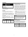
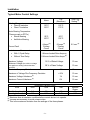
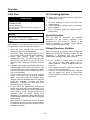
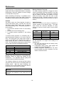
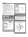
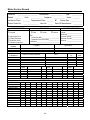
Typical Motor Control Settings
Alarm
Trip
(Shutdown)
Winding Temperature
• Class B Insulation
• Class F Insulation
130°C
155°C
155°C
170°C
Motor Bearing Temperature
(Thermocouple or RTD’s)
• Sleeve Bearing
• Antifriction Bearing
90°C
100°C
95°C
105°C
4 Amps (2)
Primary
Circuit
8 Amps (2)
Primary
Circuit
Ground Fault
Timer Trip
Setting (1)
0.2 sec. (2)
Instantaneous Overcurrent
•
•
With ½ Cycle Delay
Without Time Delay
1.8 times Locked Rotor Amps (2)
2.4 times Locked Rotor Amps (2)
Maximum Voltage
Minimum Voltage (the minimum voltage
110 % of Rated Voltage
10 sec.
90 % of Rated Voltage
10 sec.
Maximum Frequency Deviation
±5%
10 sec.
Maximum of Voltage Plus Frequency Deviation
±10%
10 sec.
Maximum Voltage Unbalance (3)
1%
15 sec.
Maximum Current Unbalance (3)
8%
15 sec.
Suggested Vibration Limits
3600
1800
1200
3.3
0.25
4.3
0.25
900 and
Slower
5.0
0.25
also applies to starting unless otherwise
specified)
RPM
Shaft (mils, pk-to-pk)
Housing (in./sec.)
3.7
0.25
(1)
Maximum time at maximum condition before control device is to operate.
Increase as necessary to avoid nuisance trips.
(3)
This is the maximum deviation from the average of the three phases.
(2)
-9-