1
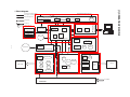
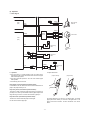
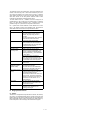
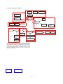
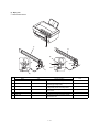
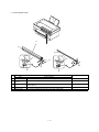
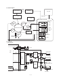
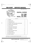
SERVICE MANUAL CODE: 00ZAL840//B1E BASIC MANUAL DIGITAL COPIER MODEL AL-800/840 CONTENTS [ 1 ] OPERATING PRINCIPLE . . . . . . . . . . . . . . . . . . . . . . . . . . . . . . . . 1-1 1. Block diagram . . . . . . . . . . . . . . . . . . . . . . . . . . . . . . . . . . . . . . . . . . . . 1-1 2. Outline of operations . . . . . . . . . . . . . . . . . . . . . . . . . . . . . . . . . . . . . . 1-3 A. Paper path and imaging . . . . . . . . . . . . . . . . . . . . . . . . . . . . . . . . . . . 1-3 B. Image process and data flow . . . . . . . . . . . . . . . . . . . . . . . . . . . . . . . . 1-3 3. Operations of each section . . . . . . . . . . . . . . . . . . . . . . . . . . . . . . . . 1-5 A. Paper feed, paper transport section . . . . . . . . . . . . . . . . . . . . . . . . . . 1-5 B. Scanner (reading) section . . . . . . . . . . . . . . . . . . . . . . . . . . . . . . . . . . 1-9 C. Scanner (writing) section . . . . . . . . . . . . . . . . . . . . . . . . . . . . . . . . . . 1-12 D. Image process section . . . . . . . . . . . . . . . . . . . . . . . . . . . . . . . . . . . . 1-14 E. Fusing/paper exit section . . . . . . . . . . . . . . . . . . . . . . . . . . . . . . . . . . 1-25 F. Drive section . . . . . . . . . . . . . . . . . . . . . . . . . . . . . . . . . . . . . . . . . . . 1-27 G. Electrical section . . . . . . . . . . . . . . . . . . . . . . . . . . . . . . . . . . . . . . . . 1-28 Parts marked with "!" is important for maintaining the safety of the set. Be sure to replace these parts with specified ones for maintaining the safety and performance of the set. SHARP CORPORATION This document has been published to be used for after sales service only. The contents are subject to change without notice. SCANNER (READING) SECTION Control signal, detection signal, drive signal, control data line DOCUMENT COPY LAMP Image data signal line Image (light) SCANNER HOME POSITION SENSOR LENS MIRROR LIGHT QUANTITY SENSOR SCANNER MOTOR CCD Power line OPERATION PWB COPY LAMP CONTROL PWB A/D ONVERTOR CPU MEMORY PARALLEL I/F Paper path line ASIC LAMP (LED) ICU PWB HOST(PC) KEY MEMORY ASIC FAN MOTOR SCANNER (WRITE) SECTION MCU (PCU) PWB LASER DIODO 1–1 MAIN MOTOR MOTOR DRIVER LENS MIRROR LASER BEAM SENSER POLYGON MIRROR SCANNER MOTOR HIGH VOLTAGE POWER PWB FUSING/PAPER EXIT SECTION TEMPERATURE SENSOR IMAGE PROCESS SECTION HEATER LAMP MAIN CHARGER PAPER EXIT ROLLER PRESSURE ROLLER PHOTOCONDUCTOR PRINT PWB DEVELOPING ROLLER HEAT ROLLER SEPARATION ELECTRODE PAPER FEED ROLLER PAPER WIDTH DETECTOR PAPER EMPTY DETECTOR PAPER EXIT ROLLER PAPER EXIT DETECTOR PAPER FEED SECTION PAPER FEED ROLLER CLUTCH PAPER PAPER TRAY TRANSFER ROLLER PAPER ENTRY DETECTOR TEMPERATURE FUSE AC POWER POWER PWB [1] OPERATING PRINCIPLE 1. Block diagram Scanner (writing) section Scanner (reading) section Fusing/paper exit section Image process section Paper feed section The operations of this section are composed of five processes; exposure, development, transfer, separation, and discharge. Scanner (read) section In this section, the copy lamp (cathode ray tube, Xenon lamp) radiates light onto a document, and the reflected light is detected by the image sensor (CCD element) to convert into electrical signals (analog signals), which are sent to the MCU PWB. The OPC drum is used as the photoconductor drum, and one-component toner is employed. For charging, the rotation brush is employed. For transfer, the roller is employed to eliminate ozone generation. In addition, t is compact. MCU (ICU) PWB The image data from the scanner (reading) section are converted into digital signals and subject to image process (correction, etc.), and converted into dot image data and outputted to the scanner (writing) section. The high voltage required in this section is supplied by the high voltage PWB. Fusing/paper exit section Toner is fused to the paper in the fusing/paper exit section using heat and pressure. During printing, the dot image data from the ICU PWB are outputted to the scanner (writing) section directly. The engine status data are outputted to the ICU PWB. The heat roller surface temperature is detected by the fusing temperature sensor to maintain the constant fusing temperature (155 ˚C). The loads (motor, solenoid, etc.) are controlled according to the sensor/detector signal. The heater lamp is driven by the power PWB unit. The above operation is performed by the CPU, ASIC, and memory. Operation PWB ICU PWB The operation PWB displays various information and supplied the key operation signals to the MCU (PCU) PWB. Print data (compressed data) sent from the host are developed and converted into dot image data and outputted to the scanner (writing) section. The engine status data sent from the MCU (PCU) PWB are outputted to the host (PC). High voltage power PWB The high voltage power PWB outputs the high voltage for the main charger, the developing bias, and the transfer charger. In addition, the main motor drive circuit is built into the PWB. Scanner (writing) section In this section, the dot image data sent from the MCU PWB are converted into laser beams (ON/OFF), which is scanned to form latent electrostatic images on the OPC drum. Main motor. Paper feed section The main motor drives the paper feed section, the transport section, the image process section, and the fusing section. The paper feed roller feeds paper to the transfer section. The main motor drive circuit is built into the high voltage power PWB. The paper feed operation is controlled by the paper fed roller clutch and the paper feed roller clutch solenoid. Copy lamp control PWB The copy lamp light quantity is controlled to provide necessary light quantity even though the conditions of the scanner (reading) section are changed. Image process This section is composed of the photoconductor section, the developing section, and the transfer/separation section. The images formed by laser beams in the scanner (writing) section are formed into latent electrostatic images on the photoconductor and converted into visible images by toner development. The copy lamp drive voltage is controlled by the output level of the light quantity sensor in the scanner (reading) section. Power PWB The power PWB outputs the DC power voltages (+24V, +5V, +3.3V, +12V), and drives the heater lamp. 1–2 2. Outline of operations A. Paper path and imaging Paper is fed, transported, and discharged through the path indicated with the arrow in the figure below. 1) Paper feed (Paper on the paper tray is fed to the transfer section by the paper feed roller.) 2) Image transfer (The toner image on the photoconductor is transferred onto the paper by the transfer roller.) 3) Fusing (The toner image on the paper is fused by the heat roller and the pressure roller.) 4) Paper exit (The paper is discharged to the paper exit tray by the paper exit roller.) 4 1 3 2 B. Image process and data flow (1) Copy mode C1) Images scanned by the image sensor (CCD element) is converted into electrical signals (analog signals) and outputted to the MCU PWB. (CCD unit) C2) Image data outputted from the scanner (reading) section are converted into digital signals. (CCDD0-7) C3) Image process (area separation, filter process, gamma correction, resolution conversion, zooming) is performed by the ASIC and the line memory (SRAM). The dot image data, the resolution of which is converted from 400dpi to 600dpi, are sent to the data select section. (Image data (LD)) C4) The data are passed through the data select section to the scanner (writing) section. (Image data (V DATA)) In the multi copy mode, image data of one sheet are stored in the DRAM. (Sharp version only) 1–3 (2) Printer mode P1) Print data (compressed data) are sent from the host. (Image data (Data 1 – 8) P2) Print data are developed by the ASIC and the line memory and converted into the full dot image data and sent to the data select section. (Image data)(VIDEO) P3) The data are sent through the data select section to the scanner (writing) section. (image data) (V DATA) DATA FLOW DIAGRAM P2 C2 C3 image data P1 ICU PWB (VIDEO) ASIC image data I/F (Data1~8) MCU PWB CCD PWB Image process ASIC DRAM CCD LSU unit analog image data Amplifier image data Image process A/D (CCD OUT) C1 Operation panel (CCDD0~7) SRAM 32kbitx8 Laser Data select image data (V DATA) image data(LD) SRAM 32kbitx8 DRAM DRAM DRAM 16Mbit 16Mbit 16Mbit (SC only) (SC only) (SC only) serial data CPU H8S (OP DATA/KIN1/KIN2) serial data (SDATA) CPU BUS serial data (EEPD) ROM RAM EEPROM 1–4 C4 P3 3. Operations of each section A. Paper feed, paper transport section (1) Outline The paper feed tray contains about 200 (250) sheets of paper. The paper is passed to the transfer section by the paper feed roller. The paper feed operation is controlled by the paper feed roller clutch and the paper feed roller clutch solenoid. The paper feed clutch employs the mechanical spring clutch. Paper mis-feed and paper jam are detected by the paper empty sensor and the paper entry sensor. The paper size (width) is detected by the paper size (width) detector to prevent toner from attaching to the area over the paper width. (2) Major parts 2) 3) 1) PE SENSOR 9) PAPER SIZE SW 10) 4) 11) 4) 5) PUS 6) 8) 6) 7) PIN SENSOR 13) 12) 13) 16) 14) 16) 18) 19) 15) 8) 17) 12) 19) 1–5 No. 1 Parts Code PE SENSOR Signal name PEMP IN Name Paper empty detector Type Function/operation Photo transmission sensor Detects paper on the paper tray. 2 Paper guide Adjust the paper width. 3 Paper feed tray Sets the print paper. (Capacity: XXX sheets) 4 Paper release lever Put this lever straight to set paper to release paper feed. Put this lever down to enable paper feed. Paper feed clutch solenoid Controls (on/off) the main motor drive for the paper feed roller. Paper feed release lever When the paper feed lever is put straight, this lever releases paper feed solenoid drive. This partially reduces stress to the paper feed roller clutch in removing paper. 5 PUS PUS 6 7 PIN SENSOR PIN 8 9 Paper in detector Photo transmission sensor Paper feed roller PAPER SIZE SW PAPER SIZE IN Paper width detector Detects whether the fed paper is transported to the transfer position or not. By the timing of this detector signal, the relative positions of paper and print image are controlled. Active condition LOW (0V) when paper is detected. LOW (0V) when paper is detected. Feeds paper. Mechanical switch (Micro switch) Detects the paper width. This signal controls the laser beam radiation area. 10 Paper pressure plate Presses paper onto the paper feed roller. 11 Paper pressure spring Presses paper onto the paper feed roller. 12 Paper separator Separates paper in paper feed operation. 13 Paper feed clutch 14 Paper feed clutch lever Driven by the paper feed clutch solenoid to control ON/OFF of the paper feed clutch. Prevents against reverse rotation of the paper feed roller. 15 Paper feed clutch joint Links the paper feed roller and the paper feed roller clutch. 16 Paper feed clutch sleeve Controls ON/OFF of the paper feed roller. (The paper feed roller is driven by the paper feed clutch solenoid and the main motor.) 17 Paper feed clutch spring Transmits the paper feed clutch rotation to the paper feed clutch sleeve. 18 Paper feed clutch gear Transmits the main motor power to the paper reed roller. 19 Paper separater spring Applies a proper pressure to the paper separater. Mechanical spring type clutch Controls ON/OFF of the paper feed roller. (The paper feed roller is driven by the paper feed clutch solenoid and the main motor. 1–6 LOW (0V) when the max. width is detected. Note (3) Operation a. Block diagram MCU(PCU)PWB High voltage power PWB +24V ASIC (IC8) CN805 Paper pickup solenoid 1 +24V 2 PUS PUS MEN CN804 MMT0 MMT1 1 2 3 4 Motor driver CPU MA MAMB MB- Main motor (IC5) +5V PIN PD801 Paper entry roller Paper feed roller +5V POUT- CN7 1 +5V 2 POUT 3 GND PD802 LSU PWB PE CN9 9 PE CN601 9 PE Paper exit roller +24V PD601 Paper empty roller * Paper release lever b. Operation * The main motor is a 4-phase stepping motor of 2-phase excitement bipolar system, which serves as the drive source of the paper feed and transport system. (Paper release) (Paper fixed) * The pickup solenoid operates on 24V and turns ON/OFF paper feed operation. * The following sensors are used. Paper empty sensor (transmission photo transistor): It is installed on the LSU PWB and is used to detect whether there is paper in the paper feed tray or not. Paper entry sensor (Transmission photo transistor): This sensor is used to detect the paper feed timing of next paper (in pre-feed) and to make synchronization between paper transport and image forming on the drum. It is also used to detect a paper jam. Paper exit sensor (Transmission photo transistor): This sensor is used to detect that paper is discharged. The paper release lever is used to fix or release paper. To release paper, pull the lever toward you as shown in the figure below. To fix paper, push the lever forward. The lever mechanism is as shown below. It is also used to detect a paper jam. 1–7 (Paper fixing operation) (Paper release operation) Notch When the paper release lever is pushed down, the paper release lever arm pushes the lock lever arm in the direction of arrow (A). Lower frame By the above operation, the rotating disk is lifted and the paper is pushed by the paper feed roller. If printing is made without pushing down the paper release lever, the lock lever arm is pushed by the paper feed roller gear boss in the direction of arrow (A) and the paper feed tray is pushed to fix the paper. Lock lever arm Lock lever * Paper feed roller, paper feed solenoid Spring Paper feed solenoid Paper feed tray Paper release lever Paper feed roller Paper feed clutch Paper feed clutch Clearance The paper feed solenoid is used to turn ON/OFF the paper feed clutch. When the paper feed solenoid is turned on, the paper feed roller is rotated. The lock lever arm is always pressed onto the paper release lever by the spring. When the paper release lever is pulled toward you, the lock lever arm is brought into contact with the lower frame so that the paper pressure plate is fixed at the paper release position. Under this condition, a clearance is provided between the paper feed roller and the paper feed tray as shown in the figure below, and the paper is released. ON Paper release lever Paper feed roller Sub release lever Paper plessure plate paper feed clutch A Lock lever arm (A) Paper feed roller gear The paper feed clutch is a spring clutch. The paper feed roller gear rotation is transmitted to the paper feed roller only in the direction of (A). That is, the paper feed roller is rotated only in the direction of (A) (paper feed direction). Paper release lever Paper feed clutch 1–8 B. Scanner (reading) section (1) Outline In this section, the copy lamp (Xenon lamp) radiates light onto a document, and the reflected light is detected by the image sensor (CCD element) to convert into electrical signals (analog signals), which are sent to the MCU PWB. Paper feed roller Separate sheet The paper feed roller is of circular form, and double paper feed is prevented by the separate sheet. Paper feed clutch lever Clutch R sleeve The paper feed clutch lever is provided to prevent the paper feed roller from rotating reversely. When paper feed is not performed, the paper feed clutch lever is engaged with the paper feed roller boss gear. When removing paper for paper replacement, a reverse rotation power is applied to the paper feed roller. In this case, the paper feed solenoid provides enough power to prevent the paper feed roller from rotating reversely, however an excessive stress is applied to the spring clutch, which may be damaged. Therefore the paper feed clutch lever is used to lock and protect the spring clutch from an excessive stress. 1–9 (2) Major parts 10) 11) 1) 2) 4) MHPS 6) CCD SENSOR 8) SL SENSOR 5) 3) 2) 7) 4) MHPS 10) 8) SL SENSOR 7) 6) CCD SENSOR 9) 11) No. 1 Name Scanner lamp control PWB 2 Scanner drive wire 3 4 Code MHPS Signal name MHPS 5 6 Photo transmission sensor Lens CCD SENSOR CCD OUT 7 8 Scanner motor Scanner home position sensor Parts Type CCD (Image) sensor CCD Scanner lamp SL SENSOR PDA/PDK Scanner lamp light quantity sensor 9 No. 1 mirror 10 No. 2 mirror 11 No. 3 mirror Photo diode 1 – 10 9) Function/operation Drives the scanner lamp. Maintains the lamp light quantity at a constant level. Transmits the scanner motor power to the scanner unit. Drives the scanner unit. Detects the scanner home position. By this signal the image scanning operation is controlled. Transfers the document image to CCD. Scans the document images (photo signals) and converts them into electrical signals. Radiates light to the document to allow the CCD to scan the document images. Detects the scanner lamp light quantity. This signal is inputted to the scanner lamp control PWB to control the scanner lamp drive voltage to maintain a constant level of light quantity. Leads the document image to CCD. Leads the document image to CCD. Leads the document image to CCD. 5) Active condition HIGH (5V) when the home position is detected. Digital signal (8Bit) Analog signal (0 ∼ 0.5V) 3) Note (3) Operation a. Wiring diagram MCU(PCU) PWB IC112 ASIC IC8 CCDD0 CCDD1 CCDD2 CCDD3 CCDD4 CCDD5 CCDD6 CCDD7 A/D 5V 5V 12V GND A-GND CCDOUT A-GND A5V 5V 12V GND f1 GND f2 GND SHGND RS GND SP GND CP GND NC GND 1 2 3 4 5 6 7 8 9 10 11 12 13 14 15 16 17 18 19 20 21 22 1 2 3 4 5 6 7 8 9 10 11 12 13 14 15 16 17 18 19 20 21 22 D-GND A-GND CCDOUT A-GND A5V 5V 12V D-GND f1 D-GND f2 D-GND SHD-GND RS D-GND SP D-GND CP D-GND NC D-GND CCD UNIT RAMP UNIT CN2 CLCNT 1 2 3 4 5 6 7 CN10 CFL-H FGND PDA PDK CFL-L INVERTER UNIT CN1 24V P-GND CL-CNT CL-IN 1 2 3 4 MRMT0 MRMT1 MRMT2 MRMT3 24V-mir 1 2 3 4 5 GND MHPS 5V 1 2 3 1 2 3 4 24V P-GND ON/OFF PD (Not used) CPU IC13 IC5 MRMT0 MRMT1 MRMT2 MRMT3 DRIVER 24V SCANER MOTOR MRPS1 MRPS2 MHPS * Copy lamp 1 2 3 GND MHPS 5V SCANER H.P SENSOR The copy lamp drive voltage corresponding to the sensor output level (CLIN) is outputted. A cathode ray tube (Xenon lamp) is used as the light source for reading images. The copy lamp is driven by the scanner lamp control PWB. To maintain the lamp light quantity at constant level, the following operations are performed. The copy lamp light quantity sensor is provided in the scanner unit to detect the copy lamp light quantity. 1 – 11 * CCD unit * Scanner home position sensor Images (light) is converted into an electrical signal (analog signal) by the CCD. The scanner home position sensor senses the scanner position. The copy image position control is performed by the sensing timing of this sensor. The image signal read by the CCD is converted into a digital signal b the A/D convertor in the MCU PWB and outputted to the ASIC, where the image is processed. * Zooming Zooming is performed by changing the copy magnification ratio in the sub scanning direction or changing the scanning speed. * Scanner motor The scanner unit is driven by the scanner drive motor. The copy magnification ratio in the main scanning direction is changed by the software in the ASIC. C. Scanner (writing) section (1) Outline In this section, the dot image data sent from the MCU PWB are converted into laser beams (ON/OFF), which are scanned to form latent electrostatic images on the OPC drum. It is composed of the laser beam generating section (where dot image data signals are converted into laser beams (ON/OFF)), the laser beam correction section, the laser beam scanning section, and the laser beam detecting section. The major parts and their functions are described in the following. (2) Block diagram Scanning motor drive signal (PMD, PMCLK) MCU VIDEO (PCU) SYNC Drum Laser diode control circuit Laser diode No. 2 reflection mirror (curved mirror) Laser beam sensor No. 2 cylinder lens Collimator lens No. 1 cylinder lens No. 1 reflection mirror Motor mirror No. 3 reflection mirror Signal Laser beam (3) Major parts 2) 1) SYNC 3) 8) 7) 4) 6) 1 – 12 5) Parts No. 1 Code Signal name SYNC SYNC IN Name Type Laser beam sensor Function/operation Bin diode Active condition Detects the laser beam position. By this signal the left image print start position is controlled. Note LOW (0V) when laser beam is detected. 2 No. 1 mirror 3 No. 3 mirror Leads the laser beam to the OPC drum. 4 Second cylindrical lens Corrects the laser beam deflection by variations in the scanning mirror angle. Corrects the optical section dirt. 5 Fθ mirror (No. 2 mirror) Corrects the laser beam form and pitch. 6 Scanning mirror (rotation mirror) Scans the laser beam and performs imaging. 7 No. 1 cylindrical lens Adjust the direction of laser beam. 8 Laser diode Generates laser beam. (Controls ON/OFF for imaging) (4) Operation a. Wiring diagram LSU PWB MCU(PCU) PWB CPU (IC5) PMCLK +24V CN9 SAMP ASIC LEND- (IC8) SYNCAPCSTT PMD- Laser beam detection PWB (start position detection PWB) IC603 3-termina 3 regulator 1 CN601 1 +24V 1 +24V 2 GND 2 GND 3 VDATA 3 VDATA 4 SAMP 4 SAMP 5 SYNC- 5 SYNC- 2 CN603 1 +5VL +5VL 2 SYNC_ 2 SYNC_ 3 GND 3 GND CN602 6 APCSTT 6 APCSTT 7 PMCLK 7 PMCLK 3 +24V 8 PMD- 8 PMD- 1 PMD- +24V CN604 1 Scanning motor 2 +24V VSYNC 4 PMCLK 5 GND PRSTT Q603 5 GND SDATA LEND LD /PD VR601 8 +5VL PRSTT 4 VSYNC 3 SYNC GND 5 VDD (IC202) 7 IM CONT ASIC OUT IC601 3 VPS 4 VCC CN203 1 INH CN8 IC603 O/I 2 I/O 1 ICU PWB b. Operation When the laser diode is turned on, 780nm infrared semiconductor laser beams are radiated from the laser diode and arranged to be parallel beams by the collimeter lens and focused to the photoconductor drum by No. 1 cylinder lens and sent to the scanning mirror. The APC circuit is started by the APCSTT signal sent from the MCU (PCU) PWB, and laser diode is turned on/off according to the VIDEO signal. (The laser diode is turned on when the VDATA signal is HIGH.) Rotation of the scanning mirror is controlled by the scanning motor to scan laser beams. 1 – 13 The scanning mirror is a 6-surface mirror. Six lines are printed for one rotation of the scanning motor. Laser beams reflected by the scanning mirror are passed to the curved mirror by the No. 1 reflection mirror. Before reaching the curved mirror, the laser beams enter the laser beam sensor on the start position detection PWB to make horizontal synchronization (generating SYNC signal). The laser beams from No. 1 reflection mirror are arranged to be parallel beams by the curved mirror and passed to No. 3 reflection mirror. The laser beams reflected by No. 3 reflection mirror are passed through No. 2 cylinder lens to the photoconductor drum. No. 2 cylinder lens corrects deflection of laser beams due to variations in the duplex scanning mirror installing angle, and leads the stable laser beams for each line to the photoconductor drum. Part name Function Laser diode The laser power is controlled by the APC (Auto Power Control) circuit. In addition, the paper empty sensor is provided. The laser diode radiates 780nm infrared semiconductor laser beams under control of the laser control PWB. Collimator lens The collimator lens arranges laser beams radiated from the laser diode to be parallel beams and converges them on the photoconductor drum. No. 1 cylindrical lens Adjusts the direction of the laser beams. Scanning motor/ Scanning mirror Used to rotate the scanning mirror. Started by the drive signal (PMD_) from the PCU. The RPM is controlled by the clock signal (PMCLK_). The motor RPM is 11811 RPM. The scanning mirror is a6-surface mirror, and it reflects laser beams. By this operation, 6 lines of printing is made for one rotation of the scanning motor. No. 1 mirror This mirror reflects laser beams to the curved mirror. Laser beam sensor PWB (Start position detection PWB) Used to detect laser beams to make horizontal synchronization. The photo sensor on the PWB detects laser beams to generate SYNC signal. No. 2 mirror (Curved mirror) Laser beams are scanned by the scanning mirror. But the dot interval of laser beams radiated onto the photoconductor differs at the center and at the corners. This mirror corrects this difference to provide even dot interval of laser beams. For this reason, it is of curved structure. No. 3 mirror This mirror passes the laser beams reflected from the curved mirror to the photoconductor mirror. No. 2 cylindrical lens This lens is used to correct laser beam deflection due to variations in the scanning mirror angle. D. Image process section (1) Outline This section is composed of the photoconductor section, the developing section, the transfer/separation section. Images formed by laser beams formed by the scanner (Writing) section are converted into a latent electrostatic images, which are formed into visible images by toner development. The toner images are transferred onto paper. 1 – 14 (2) Image forming process diagram Scanning mirror High voltage circuit Laser diode Lens No. 1 No. 3 mirror Main charger brush Exposure Toner Cleaning, charging Development, residual toner collection High voltage circuit Paper exit Discharging brush Fusing Discharging Development roller Separation Transfer Separation electrode Heat roller, pressure roller High voltage circuit Transfer charger roller High voltage circuit Heater lamp The operation of this section are composed of the six processes: charging, exposure, development, transfer, separation, and discharging. An OPC drum is used as the photocoductor drum. Toner is of one-component. For charging, the rotation brush is used. For transfer, the roller is used and virtually no generation of ozone. It is also compact. The high voltage required in this section is provided by the high voltage power PWB. 1 – 15 Paper feed roller Paper tray Paper (3) Major parts a. Photoconductor section 1) 5) 6) 3) 5) 4) 2) 1) Parts No. Name Type OPC Note Function/operation 1 OPC drum 2 OPC drum earth electrode Forms latent electrostatic images. Connects the OPC drum aluminum layer and the earth (high voltage PWB). 3 Main charger electrode Connects the main charger output (high voltage PWB) and the main charger brush. 4 Discharge brush Discharges (lower the potential of) the OPC drum surface. 5 Main charger brush Charges the OPC drum. 6 Toner seal Shield to prevent toner from leaking outside the OPC drum unit. 1 – 16 Japan only b. Development section 5) 2) 1) 7) 8) 5) 1) 3) 3) 6) 4) 4) 8) 5) 1) No. Parts Name Type Function/operation 1 Developing roller Attaches toner to the latent electrostatic images on the OPC drum to convert it into a visible image. 2 Developing doctor Controls toner quantity on the developing roller and charges toner. 3 Developing bias electrode Connects the developing roller and the bias voltage output (high voltage PWB). 4 Potential control electrode Connects the developing roller and the bias voltage output (high voltage PWB). 5 Toner stirring roller Lead toner to the developing roller and charges toner. 6 Zenor diode Maintains the potential between the developing roller and the toner stirring roller at a constant level. 7 Toner seal Shields toner from leaking outside the developing unit. 8 Potential control sheet Maintains the developing roller potential at a constant level. 1 – 17 Note c. Transfer/separation section 1) 3) 4) 3) 5) 2) 1) No. 4) Parts Name Function/operation 1 Transfer roller Transfers toner images on the OPC drum onto the paper. 2 Transfer roller electrode Connects the transfer roller and the transfer voltage output (high voltage PWB). 3 Pressure spring Applies pressure to the transfer roller, paper, and the OPC drum to improve transfer efficiency. 4 Separation electrode Reduces paper charging potential to facilitate separation of paper. 5 Earth electrode Connects the separation electrode and the earth (high voltage PWB). 1 – 18 Note (4) System diagram Scanning mirror Laser beam Laser unit MCU PWB No. 1 - 4 mirror Image data Toner High voltage power PWB –310V/+200V selection Main charger brush DC –310V DC-310V Developing roller DC +200V Photoconductor drum DC +3.5KV AC600V(P-P) DC-200V Discharge brush DC –850V Paper Transfer charger roller DC-850V AC600V(P-P) Separation electrode DC+500V (5) Operation a. Wiring diagram MCU(PCU) PWB CN6 TSIN +5V 3 GND 2 TSIN 1 Toner sensor High voltage power PWB ASIC (IC8) Charger brush MCON Q804 MC T801 transformer CB Discharge brush +24VP DRUM EARTH Driver I C801 OPC drum +24VP Separation electrode TC/Bias ON Q806 TC Q807 Transfer charger roller T802 transformer Q803 DC Bias Supply roller Q808 CPU (IC5) 100V PWNSIN Developing roller Earth sheet 1 – 19 b. Major parts functions and operations <2> Developing unit Visible images are formed with toner over the latent electrostatic images formed on the OPC drum surface. Toner is filled in the developing unit. 1) Developing roller 3) The developing roller is made of urethane and it has considerably high electrical resistance. It is flexible and pressed onto the OPC drum. Toner is attached to the latent electrostatic images on the OPC drum to make visible images. A voltage of DC-310V/+200V is applied to the developing roller. A voltage of –310V is applied when developing. A voltage of +220V is applied when cleaning. 1) 11) 2) 10) 4) 2) Doctor 9) The doctor is pressed onto the developing roller. It adjust the toner quantity on the developing roller surface. 12) The doctor is made of a conductive material. 3) Toner supply roller 5) 8) 7) The toner supply roller transports toner to the developing roller. 4) Toner stirring plate 6) The toner stirring plate stirs toner in the developing unit to transport toner to the developing roller smoothly. 1 Developing roller 5 Toner seal 2 Doctor 6 Transfer charger roller 3 Toner stirring plate 7 4 Toner supply roller 8 9 Discharge brush 5) Toner seal 10 Main charger brush The toner seal prevents toner from leaking outside the developing unit. Separation electrode 11 Toner seal 6) Discharge (Earth) sheet Phot conductor drum 12 Discharge (Earth) sheet The discharge sheet maintains the developing roller surface potential at a constant level. <3> Transfer charger roller <1> Photoconductor drum unit The transfer charger roller is made of urethane and its electrical resistance is considerably high. It is flexible and pressed onto the OPC drum. The photoconductor surface is charged and latent electrostatic images are formed, then visible images are formed with toner. A high voltage of AC600V (P-P) is applied to DC +3500V. 1) Photoconductor drum Latent electrostatic images are formed and visible images are formed with toner. Paper transported from the paper feed section is charged positively and negatively charged toner on the OPC drum are transferred onto the paper. An OPC (Organic Photo Conductor) drum is used. The OPC drum surface is negatively charged by the main charger brush. During cleaning, a voltage of –850V is applied. <4> Separation electrode When laser beams are radiated on the OPC drum, the electric resistance at the radiated area is reduced to generate an electric charge inside the OPC drum. As a result, the charges on the OPC drum are removed. This process is used to form latent electrostatic images. OPC layer The separation electrode is connected to the drum earth. This discharges paper charged positively in the transfer section to reduce potential difference with the OPC drum, reducing electrostatic attraction power between paper and the OPC drum, facilitating paper separation. CTL (Charge Transfer Layer) <5> High voltage unit CGL (Charge Generation Layer) The high voltage is made by the invertor system, and is supplied to the main charger unit, the transfer unit, and the developing roller. Aluminum layer 2) Main charger brush The main charger brush charges the OPC drum surface. It is composed of brush textures and of a roller shape. A high voltage of AC 600V (P-P) is applied to DC-850V to charge the brush. The main charger brush is in contact with the OPC drum. By supplying electric charges to the OPC drum, the OPC drum is charged to about –850V. 3) Toner seal The OPC drum has two toner seals. The toner seals are used to prevent residual toner on the OPC drum from leaking outside. 1 – 20 c. Actual image forming process Step 2 (Exposure); Laser beam scanning light corresponding to the print data is radiated onto the OPC drum. Step 1 (Cleaning, charging): Residual toner on the OPC drum is stirred and negative charges are distributed evenly on the OPC drum. (The OPC drum is evenly charged.) Positive and negative charges are generated in the CGL of the OPC drum which are radiated with laser beams. The positive charges in the CGL are moved to the OPC drum surface, and the negative charges are moved to the aluminum layer. The main charger brush is of roller shape and is rotating. Therefore, positive and negative charges are neutralized in the OPC drum exposed with laser beams and the aluminum layer, reducing the OPC drum surface potential. On the other hand, there is no change in the area which is not exposed with laser beams. So the OPC drum surface is kept negatively charged to maintain a high potential. As a result, latent electrostatic images are formed on the OPC drum. The main charger brush stirrs residual toner and paper dust on the OPC drum. At the same time, a high voltage of AC 600V (P-P) is applied to DC –850V and applied to the main charger brush to make electric discharge between the roller and the OPC drum to form positive and negative charges. The negative charges are attracted to the OPC drum which is positively charged. And negative charges are evenly distributed on the OPC drum. (The OPC drum surface is evenly charged.) Residual toner and paper dust stirred by the main charger brush are distributed evenly on the OPC drum. Laser beam Main charger brush Non-exposure area Exposure area CTL CGL AC600V (P-P) Aluminum layer (Drum base) Residual toner OPC drum DC-850V CTL CGL Aluminum layer (Drum base) CTL CGL Aluminum layer (Drum base) 1 – 21 Step 3 (Development): Toner is attached to the latent electrostatic images formed on the OPC drum. At that time, the potential of the OPC drum surface where there is no charge by exposure of laser beams is higher than the developing roller potential. On the other hand, there are negative charges in the OPC drum surface area which is not exposed to laser beams. When that area is brought into contact with the developing roller, if toner is attached to the OPC drum,. toner is moved to the developing roller which is in a high potential than the OPC drum. As a result, unnecessary toner and paper dust on the OPC drum are collected in the developing unit. In this operation, toner is moved from the OPC drum to the developing roller. In cleaning operation mode, DC +200V is applied to the developing roller and cleaning capacity is further increased. Step 4 (Transfer): Visible images of toner on the OPC drum are transferred to the paper. :Toner (Negative charge) Doctor Developing roller Toner supply roller 100V OPC drum Exposure area (Exposed by laser beams.) Earth sheet Aluminum surface (Drum base) Non-exposure area (Not exposed by laser beams.) CGL OPC drum Aluminum layer CGL (Drum base) DC +200V CTL DC -310V CTL Paper Toner enters between the developing roller and the doctor, and a thin layer of toner (a certain fixed amount) is formed on the developing roller by a pressure applied to the doctor. Toner is negatively charged by friction when passing between the developing roller and the doctor. When the OPC drum surface area where there is no charges because of exposure of laser beams is brought into contact with the developing roller, toner is moved from the developing roller to the OPC drum surface. The principle of the process is as follows: Transfer roller A bias voltage of –310V is applied to the developing roller. Toner which is charged by potential difference between the bias voltage and the OPC drum surface potential is attracted to the OPC drum surface (positively charged). DC+3500V AC600V(P-P) DC –850V A high voltage of AC60V (P-P) is applied to DC+350V and applied to the transfer roller, generating electric discharge between the roller and the OPC drum, generating positive and negative charges. 1 – 22 The positive charges are attracted to the OPC drum which is negatively charged, and put on the paper transported between the transfer roller and the OPC drum. The paper, therefore, is charged positively. Step 6 (Discharging): The drum surface is discharged by the discharge brush to facilitate cleaning. (Residual toner can be easily collected by the main charger roller.) The negative charged toner on the OPC drum is attracted to the paper which is positively charged and visible images of toner are transferred onto the paper. Step 7 (Cleaning): Residual toner on the OPC drum is removed. In the cleaning mode, a voltage of –850 V is applied. If there is toner on the transfer roller, the toner is attracted to the OPC drum. Step 5 (Paper separation): Paper is separated from the OPC drum. Main charger brush Aluminum layer (Drum base) CGL CTL AC600V (P-P) Residual toner Paper OPC drum DC-850V Separation electrode Discharge brush CTL CGL Aluminum layer (Drum base) Transfer roller DC+500V An electric force is acting between the paper which is positively charged in the transfer process and the OPC drum which is negatively charged. Positive charges on the paper are moved to the aluminum layer through the separation electrode to reduce the potential difference between the OPC drum and the paper. By this operation, the paper can be easily separated from the OPC drum. The main charger brush is of roller shape and is rotating. The main charger brush stirs residual toner and paper dust on the OPC drum. The residual toner and paper dust are evenly distributed and put on the OPC drum again to be sent to the developing roller. 1 – 23 d. OPC drum surface potential <2> OPC drum surface potential and developing bias voltage during developing <1> OPC drum surface potential shift in printing -310V OPC drum surface potential (-V) -850V Start Dark area potential -310V Toner attraction potential Developing bias Light area potential Charging/ cleaning Exposure Residual toner Transfer collection/ Development OPC drum surface potential (-V) Laser beams During developing Dark area potential Developing bias Light area potential Time (OPC drum rotating angle) Charging Time (OPC drum rotating angle) 1 – 24 End E. Fusing/paper exit section (1) Outline Toner attracted to the paper in the transfer section is fused by heat and pressure of the heat roller. The heat roller is of thin aluminum roller which is high heat conductivity, minimizing the warm up time. The heat roller surface temperature is detected by the fusing temperature sensor to maintain the fusing temperature at a constant level (160/155 ˚C). (2) Major parts 11) 7) 11) 8) 8) 7) 6) 2) POUT 3) 1) 4) 9) 5) 4) 5) 9) 9) 10) 2) POUT 10) 1) 6) 11) 3) No. Code Signal name Name Heat roller POUT POUT IN Paper exit detector 1 2 3 RTH IN 4 5 6 HL Fusing temperature sensor Temperature fuse 1 (Fusing section) Temperature fuse 2 (Fusing section) Heater lamp 7 Pressure roller 8 9 Paper exit roller Separation pawl 10 Paper exit roller 11 Pressure spring Parts Type Photo transmission sensor Thermistor Function/operation Active condition Heats toner on the paper and LOW (0V) when fuses onto the paper. paper is detected. Detects paper exit. Mold Detects the heat roller surface temperature. Assures safety in overheating. Mold Assures safety in overheating. Halogen lamp Heats the heat roller. Applies a pressure to the heat roller and paper to improve fusing efficiency. Discharges paper after fusing. Separates paper from the fusing roller mechanically. Discharges paper outside the machine after fusing. Applies a pressure to the heat roller, paper, and pressure roller to improve transfer efficiency. 1 – 25 MODEL Note 100V series 10V 500W 120V series 120V 500W 200V series 230V 500W (3) Operation a. Wiring diagram MCU(PCU) PWB POWER SUPPLY PWB Fusing section AC POWER IN CPU (IC5) CN603 1/3 HLL HLON- HLON Temperature fuse (132 C) Gate Temperature fuse (187 C) Heater lamp RTH CN603 2/4 HLN COMP AMP ASIC (IC202) PR Thermistor CN2 GND 1 RTHN 2 RTH PR CN801 +24V DRIVER High voltage power PWB 1 +24V 2 NC 3 +24VS b. Operation Heat roller: The heater lamp ON/OFF is controlled by the detection signal (voltage value) from the thermistor to maintain the heat roller surface temperature at the optimum level. The heat roller is made of aluminum tube coated with teflon to provide a good separation capability. Heater lamp: The heat roller surface temperature is controlled to 160/155 ˚C in the print mode and to 80 ˚C in the pre-heat mode. A halogen lamp is used as the heater lamp. Pressure roller: Silicon rubber is used to provide enough pressure. Thermistor: A chip-type thermistor of good response is used to detect the heat roller surface temperature. As a protective measure in case of abnormally high temperature in the fusing section, two temperature fuses are provided in the heater lamp power line. The heater lamp is lighted by the AC power source. Temperature fuse (132 ˚C): The temperature fuse (132 ˚C) is attached to the fusing cover. When the fusing cover ambient temperature becomes abnormally high, this fuse is blown off. Temperature fuse (187 ˚C): The temperature fuse (187 ˚C) is closely attached to the heat roller. When the heat roller temperature becomes abnormally high, this fuse is blown off. Separation pawl: 1 – 26 The separation pawl separates paper from the heat roller mechanically. F. Drive section (1) Outline The main motor drives the paper feed section, the transport section, the image process section, and the fusing section . The main motor drive circuit is built in the high voltage power PWB. (2) Major parts 1) 3) 2) No. 1 Parts Code MM Name Main motor Type Note Function, operation Stepping motor (+24V) Drives the paper feed section, the paper transport section, the fusing section, and the image process section. 2 Paper feed section drive gear Transmits the main motor power to the paper feed section. 3 Imaging process/ fusing section drive gear Transmits the main motor power to the imaging process section and the fusing section. (3) Wiring diagram MCU(PCU)PWB ASIC (IC8) High voltage power PWB Paper feed roller MEN CN804 MMT0 MMT1 CPU Motor driver 1 2 3 4 MA MAMB MB- (IC5) Main motor Heat roller Pressure roller Paper exit roller Developing cartridge Photoconductor cartridge Transfer roller 1 – 27 G. Electrical section (1) Block diagram ICU PWB ASIC I/F MCU (PCU) PWB CCD PWB Image process ASIC CCD DRAM CCD control LSU unit Amplifier Image process A/D Laser Data select Laser beam sensor Paper in sensor SRAM 32kX8 SRAM 32kX8 DRAM 16Mbit DRAM 16Mbit Motor driver Scanner motor High voltage PWB Polygon motor Paper exit sensor DRAM 16Mbit CPU H8S Pickup solenoid Driver FAN motor Motor driver Main motor Home position sensor Operation panel PWB ROM RAM EEPROM High voltage unit Key switch Display lamp Paper size sensor Toner sensor Scanner lamp Heat roller Developer cartridge Thermistor Invertor Power PWB unit Heater lamp Temperature fuse Temperature fuse Doctor Developing roller Earth sheet Transfer roller Main charger roller Drum OPC cartridge Control electrode Power SW a. Major sections operations and functions MCU (PCU) PWB The CPU controls the engine, and the ASIC performs image process. Image data (analog signals) from the scanner (reading) section are converted into digital signals by the A/D convertor and image process (area separation, filter process, gamma correction, resolution conversion, zooming) is performed by the ASIC and the line memory (SRAM). The processed data are outputted to the scanner (writing) section. During printing, the dot image data from the ICU PWB are received and outputted to the scanner (writing) section straightly. The CPU controls the machine operations according to the key operation signals from the operation PWB. The loads (motor, lamp. solenoid, high voltage power PWB, etc.) are controlled according to the sensors and detectors signals. At the same time, the machine status data are outputted to the operation section and the ICU PWB. 1 – 28 MCU PWB BLOCK DIAGRAM SCANNER MOTOR HOME POSITION SENSOR MRMT0~3 MHPS_IN CN11 CN12 INVERTOR PWB CCD PWB f1,f2, SH-,RS, CCDOUT SP,CP CLCNT CN10 IC13 CN13 CN14 IC112 PSIZE_IN PAPER SIZE SENSOR CN9 VDATA IC8 ASIC HG73C025FD IC5 CPU H8S/2350 LASER PMCLK PMD- LSU PWB RTH_IN THERMISTOR CN8 PSIZE_IN PAPER EMPTY SENSOR DSRDY-,RESERRDPAGE-,VIDEO VSYNC-,PRSTT RESET,DREADYDCRDY-,ERROR SCLK,SYNC ICU PWB CN2 PAPER EXIT SENSOR CN7 PEMP_IN POLYGON MOTOR CN1 OPCLK,OPLATCH OPPSW OPDATA,SELIN1,2,3OPKIN1,2 OPERATION PANEL CN5 CN4 VFMOUT MEN-,MMT0,1 MCON,HL,TC/BIASON PUS,PR,PWMSIN FAN MOTOR CN6 PIN_INFW HIGH VOLTAGE PWB ICU PWB TS_IN TONER SENSOR OPERATION PWB BLOCK DIAGRAM Print data from the host (PC) are developed by the ASIC and the line memory (DRAM) to converted into full dot image data, which are then outputted to the data select section in the MCU PWB. The machine status data from the MCU PWB are outputted tot he host (PC). In addition. the ASIC controls the parallel I/F. LAMP, VALUE DISPLAY LED DISPLAY CONTROLLER (DRIVER) IC901 ICU PWB MCU PWB CN-901 DECODER IC902 CN202 MCU PWB TO PC KEY SWITCH CN203 IC202 GATE ARRAY High voltage power PWB IC201 DRAM CN201 This PWB supplies the high voltage used in the image process section. (Main charger, developing bias, transfer charger) It also includes the driver for the main motor. The power output is controlled by the control signals from the MCU (PCU) PWB. TO PC Copy lamp control PWB The copy lamp light quantity is controlled so that the necessary quantity of light is provided even when conditions of the scanner (reading) section are changed. Operation PWB Status data from the MCU PWB are converted into the lamp and lamp display by the display controller. The key operations are converted into key data signals and outputted to the MCU (PCU) PWB. The copy lamp drive voltage is controlled by the output level of the light quantity sensor in the scanner (reading) section. Control is made with the control signals from the MCU (PCU) PWB. Power PWB The power PWB outputs DC power voltages (+24V, +5V, +3.3V, +12V) and drives the heater lamp. 1 – 29 q COPYRIGHT 1998 BY SHARP CORPORATION All rights reserved. Printed in Japan. No part of this publication may be reproduced, stored in a retrieval system, or transmitted. In any form or by any means, electronic, mechanical, photocopying, recording, or otherwise, without prior written permission of the publisher. SHARP CORPORATION Printing Reprographic Systems Group Quality & Reliability Control Center Yamatokoriyama, Nara 639-1186, Japan 1998 October Printed in Japan S