1
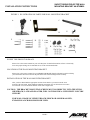
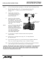
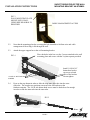
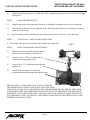
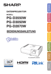
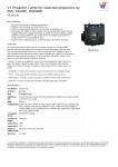
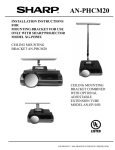
MODEL AN-STWM20
INSTALLATION INSTRUCTIONS FOR SHORT THROW PROJECTOR
WALL MOUNTING BRACKET FOR USE WITH SHARP PROJECTOR
MODEL NOS. PG-F267X, PG-D2870W
AN-STWM20 SHORT THROW
WALL MOUNTING BRACKET
WITH EXTENSION
COLOR: WHITE
AVDEX CORPORATION
115 HENRY STREET, FREEPORT, NY 11520
TEL: 516-546-2272 FAX: 516-623-7766 TOLL FREE: 1-800-866-1820
E-MAIL: [email protected]
SHORT THROW PROJECTOR WALL
MOUNTING BRACKET AN-STWM20
INSTALLATION INSTRUCTIONS
C A U T I O N
INSTALLATION OF THIS ADJUSTABLE WALL MOUNTING
BRACKET SHOULD BE PERFORMED BY QUALIFIED SERVICE/
INSTALLATION PERSONNEL FOLLOWING THE INSTALLATION
INSTRUCTIONS INCLUDED WITH THIS BRACKET
THE EXCLAMATION POINT WITHIN AN EQUILATERAL TRIANGLE
IS INTENDED TO ALERT THE USER TO THE PRESENCE OF IMPORTANT
OPERATING AND MAINTENANCE (SERVICING) INSTRUCTIONS IN THE
LITERATURE ACCOMPANYING THE APPLIANCE.
IMPORTANT! THE INSTALLER SHOULD READ THESE INSTRUCTIONS
THOROUGHLY BEFORE BEGINNING THE INSTALLATION AND SHOULD MAKE SURE
THAT ALL THE WORK IS DONE IN COMPLIANCE WITH NEC AND ALL LOCAL
BUILDING AND SAFETY CODES. SAVE THIS BOOKLET AFTER THE INSTALLATION
IS COMPLETED. THE ACCESSORIES REFERRED TO IN THESE INSTRUCTIONS ARE
INTENDED FOR USE ONLY WITH COMPATIBLE SHARP PROJECTORS. SEE
SHARP PROJECTOR OWNER’S MANUAL OR SHARP DEALER TO DETERMINE
SUITABILITY.
CAUTION: THE BRACKET MOUNTING SCREWS MUST GO DIRECTLY INTO THE
BEAMS. SHEETROCK, LATH AND PLASTER, WILL NOT PROVIDE A
SUFFICIENTLY SECURE SUPPORT.
CAUTION: TO REDUCE THE RISK OF PERSONAL INJURY, USE ONLY THE
COMPONENTS WHICH ARE INCLUDED IN THIS PACKAGE, OR SPECIFIED IN
THESE INSTRUCTIONS.
PARTS LIST FOR MODEL AN-STWM20
SHORT THROW PROJECTOR WALL MOUNTING BRACKET (SEE FIG. 1)
ITEM
A.
B.
C.
D.
E.
F.
G.
H.
I.
J.
K.
L.
M.
N.
DESCRIPTION
QUANTITY
MOUNTING TWIST ASSEMBLY FOR ATTACHMENT TO BOTTOM OF PROJECTOR INCLUDES
DUAL POSITIONING ASSEMBLY
MAIN WALL MOUNTING BRACKET ASSEMBLY WHICH INCLUDES OUTER EXTENSION TUBE
DIAGONAL BRACE
INNER EXTENSION TUBE
END STOP FOR INNER EXTENTION TUBE
1/4 X 10 HEX HEAD LAG BOLTS 2-1/2” LONG
1/4 X 10 HEX HEAD LAG BOLTS 3” LONG
1/4” I.D. WASHERS FOR USE WITH LAG BOLTS
M4X10 SCREWS AND WASHERS FOR USE WITH PROJECTOR ATTACHMENT PLATE
1/4-20 X 1/2” KNOB
1/4-20 X 1/4” BUTTON HEAD SOCKET CAP SCREW WITH WASHERS (BLACK) FOR EXTENSION TUBE
1/4-20 X 5/16” BUTTON HEAD SOCKET CAP SCREW FOR DIAGONAL BRACE AND END STOP
1/4-20 NYLON CAP NUTS
5/32 AND 7/32 ALLEN WRENCHES
PAGE 2
1
1
1
1
1
4
4
4
4
2
6
3
2
2
SHORT THROW PROJECTOR WALL
MOUNTING BRACKET AN-STWM20
INSTALLATION INSTRUCTIONS
FIGURE 1. ILLUSTRATION OF PARTS FOR WALL MOUNTING BRACKET
A.
B.
C.
D.
F.
G.
H.
I.
E.
D.
L.
J
K.
M
N.
INVERT THE PROJECTOR IMAGE
Please refer to the owners manual for your LCD Projector for detailed instructions of how to electrically
invert the projected image to accommodate its use in the wall mounted mode.
LOCATION OF THE WALL MOUNTING BRACKET
Please refer to the owner’s manual for your SHARP LCD PROJECTOR for information which will help
you to determine the best location for the placement of the wall mounting bracket assembly.
INSTALLATION OF THE WALL MOUNTING BRACKET
After you have determined the appropriate location for the bracket, you must locate the exact
location of the wall studs. Most standard residential construction uses 16 inches between centers
for wall studs. You can mount the bracket in line with a single beam.
CAUTION: THE BRACKET MOUNTING SCREWS MUST GO DIRECTLY INTO THE STUDS.
SHEETROCK, LATH AND PLASTER, WILL NOT PROVIDE A SUFFICIENTLY SECURE
SUPPORT.
FOR WALLS MADE OF CEMENT BLOCK, BRICK OR SOLID MASONRY,
EXPANSION ANCHORS SHOULD BE USED.
PAGE 3
SHORT THROW PROJECTOR WALL
MOUNTING BRACKET AN-STWM20
INSTALLATION INSTRUCTIONS
STEP 1.
ATTACH THE MOUNTING ASSEMBLY TO THE BOTTOM OF THE PROJECTOR.
1.1
Place the flat surface of the 4 1/4” x 5 3/8” plate against the bottom of the
Projector with the “U” shaped cut out toward the rear of the projector.
See Fig. 2
1.2
Align the plate so that the four
crescent shaped mounting slots are
over the threaded holes in the
bottom of the projector.
1.3
Install the four M4x10 mounting
Screws and washers. See Fig. 2. DO
NOT TIGHTEN. These slots will be
used to adjust the horizontal positioning
of the image on the screen during
final set up.
STEP 2.
FIG. 2
M4x10 screws
and washers
ATTACH THE WALL BRACKET TO
THE WALL. (REFER TO THE
PROJECTOR OWNERS MANUAL
FOR INFORMATION HELPFUL IN
LOCATING THE PROPER
LOCATION FOR MOUNTING
THE SUPPORT BRACKET.)
2.1.1
Use the bracket as a template to mark the location where the pilot holes
should be drilled.
2.1.2
Drill the holes for the support screws using a 1/8” (.125 inch) drill bit into
the center of the stud.
2.1.3
Screw the bracket to the studs. Use at least 4 hex head screws supplied with the unit.
These screws should be tightened firmly to insure a vibration free support.
Note: Two sizes of hex head lag bolts are provided. Use shorter screws for sheetrock surfaces
and use the longer screws for walls constructed of wood lath and plaster.
CAUTION: THE BRACKET MOUNTING SCREWS MUST GO DIRECTLY INTO THE STUDS.
SHEETROCK OR LATH AND PLASTER ALONE WILL NOT PROVIDE A SUFFICIENTLY
SECURE SUPPORT. IF THE WALL IS CEMENT BLOCK, BRICK OR SOLID MASONRY,
EXPANSION ANCHORS SHOULD BE USED.
PAGE 4
SHORT THROW PROJECTOR WALL
MOUNTING BRACKET AN-STWM20
INSTALLATION INSTRUCTIONS
FIG. 3
WALL MOUNTING PLATE
MOUNT ONTO WALL
USING HEX HEAD BOLTS
PROVIDED
CABLE MANAGEMENT ACCESS
2.2
Note that the mounting plate has a rectangular hole intended to facilitate wire and cable
management if the wiring is fed through the wall.
2.3
Attach the upper support bar to the wall mounting bracket.
FIG. 4
Place the holes in the bar over the 2 screws attached to the wall
mounting plate and secure with the 2 nylon cap nuts provided.
Install 1/4-20x5/16”
button head socket
cap screw on both
sides of the bracket.
Do not tighten
1/4-20X1/4” BUTTON HEAD
SCREWS
2.4
Press on the stop button in order to slide the long inner slide tube into the outer
slide tube. The stop has two positions, one nearer the wall and one at the
furthest extension. The 1/4-20 side button head screws must be backed out far enough
in order to slide the inner tube into the outer tube.
FIG. 5
PAGE 5
SHORT THROW PROJECTOR WALL
MOUNTING BRACKET AN-STWM20
INSTALLATION INSTRUCTIONS
2.5
Tighten the button head screws on both sides of the extension tube after you have set the desired length.
See Figure 5.
STEP 3.
HANG THE PROJECTOR
3.1
Hang the projector on the long inner slide tube by sliding the rectangular sleeve over the long tube.
3.2
Slide the sleeve forward over the long tube to the desired position and secure it with the two knobs on
either side of the sleeve.
3.4
Insert the stop onto the end of the long tube and secure with the 1/4-20x5/16” screw provided.
STEP 4.
ATTACH ALL CABLES AND POWER CORD
4. Tuck all the wires into the zig-zag slot on the topside of the long tube.
STEP 5.
FIG. 6
FINAL POSITIONING ADJUSTMENTS.
5.1
Slide the projector assembly along the tube to
adjust the size of the image on the screen.
5.2
Loosen screw “A” FIG. 6, to adjust and set
vertical positioning, tighten screw
5.3
Loosen Screw “B” to adjust horizontal tilt and
tighten screw.
5.3
Use the four mounting screws and slots
to adjust horizontal positioning and tighten screws.
SPECIAL NOTE: IN THE EVENT YOU WANT TO MOUNT
THE PROJECTOR CLOSER TO THE WALL THAN THE LONG
TUBE WILL ALLOW, YOU CAN REMOVE THE SCREWS FROM THE FAR END OF THE UPPER
SUPPORT BRACKET AND SLIDE THE SLEEVE ON THE TOP OF THE PROJECTOR MOUNTING
ASSEMBLY ON TO THE OUTER TUBE. (THE RECTANGULAR SLEEVE IS LARGE ENOUGH TO
ACCOMMODATE THIS). RE-INSTALL THE SCREWS AND POSITION THE PROJECTOR TO THE
DESIRED CLOSER LOCATION.
PAGE 6
SHORT THROW PROJECTOR WALL
MOUNTING BRACKET AN-STWM20
INSTALLATION INSTRUCTIONS
SHORT THROW PROJECTOR WALL MOUNTING BRACKET
WITH PROJECTOR MOUNT ASSEMBLY
SPECIFICATIONS SUBJECT TO CHANGE WITHOUT NOTICE
A.
B.
C.
D.
E.
F.
From bottom of extension tube to top of projector 5”
From bottom of extension tube to center of lens 7 1/4”
From mounting plate to end of attached outer tube 23 5/8”
From mounting plate to end of inner tube fully extended 64 1/8”
Weight of wall mounting bracket with projector mount 17#
Projector mounting screws M4x10mm long metric.
COLOR: WHITE
PAGE 7
ONE YEAR LIMITED WARRANTY
AVDEX Corporation warrants to the first end use purchaser, that this AVDEX brand
product (the “Product”), when shipped in its original container, will be free from defective
workmanship and materials, and agrees that it will, at its option, either repair the defect or
replace the defective product or part thereof at no charge to the purchaser for parts or for
labor, excluding costs of removal and/or installation, for one year from date of purchase.
This warranty does not apply to any appearance items of the Product nor to any Product
the exterior of which has been damaged or defaced, which has been subject to misuse,
abnormal service or handling, or which has been altered or modified in design or
construction. In order to avail the purchaser of his/her rights under this limited warranty,
the purchaser should carry in or ship the Product prepaid and insured, including proof of
purchase, to: AVDEX Corporation, 115 Henry Street, Freeport, NY 11520.
The limited warranty described above is in addition to whatever implied warranties may be
granted to purchasers by law. To the extent permitted by applicable law ALL IMPLIED
WARRANTIES INCLUDING THE WARRANTIES OF MERCHANTABILITY AND FITNESS
FOR USE ARE LIMITED TO THE PERIOD(S) FROM THE DATE OF PURCHASE SET
FORTH ABOVE. Some states do not allow limitations on how long an implied warranty
lasts, so the above limitation may not apply to you.
Neither the sales personnel of the seller nor any other person is authorized to make any
warranties other than those described above, or to extend the duration of any warranties
beyond the time period described above on behalf of AVDEX.
The warranties described above shall be the sole and exclusive warranties granted by
AVDEX and shall be the sole and exclusive remedy available to the purchaser. Correction
of defects, in the manner and for the period of time described herein, shall constitute
fulfillment of all liabilities and responsibilities of AVDEX to the purchaser with respect to
the Product, and shall constitute full satisfaction of all claims, whether based on contract,
negligence, strict liability or otherwise. In no event shall AVDEX be liable, or in any way
responsible, for any damages or defects in the Product which were caused by repairs or
attempted repairs performed by anyone other than AVDEX. Nor shall AVDEX be liable or
in any way responsible for incidental or consequential economic or property damage.
Some states do not allow the exclusion of incidental or consequential damages, so the
above exclusion may not apply to you.
THE WARRANTY GIVES YOU SPECIFIC LEGAL RIGHTS. YOU MAY ALSO HAVE
OTHER RIGHTS WHICH VARY FROM STATE TO STATE.
Specifications are subject to change without notice.
AVDEX CORPORATION, 115 HENRY STREET. FREEPORT, NEW YORK 11520
COPYRIGHT©2009 AVDEX CORPORATION